EP0683003A1 - Vorrichtung zum Positionieren und Fixieren eines Werkzeugträgers in einer Schneidvorrichtung - Google Patents
Vorrichtung zum Positionieren und Fixieren eines Werkzeugträgers in einer Schneidvorrichtung Download PDFInfo
- Publication number
- EP0683003A1 EP0683003A1 EP95106523A EP95106523A EP0683003A1 EP 0683003 A1 EP0683003 A1 EP 0683003A1 EP 95106523 A EP95106523 A EP 95106523A EP 95106523 A EP95106523 A EP 95106523A EP 0683003 A1 EP0683003 A1 EP 0683003A1
- Authority
- EP
- European Patent Office
- Prior art keywords
- centering
- locking
- tool holder
- frame
- tool
- Prior art date
- Legal status (The legal status is an assumption and is not a legal conclusion. Google has not performed a legal analysis and makes no representation as to the accuracy of the status listed.)
- Granted
Links
- 230000000903 blocking effect Effects 0.000 title description 2
- 241000272201 Columbiformes Species 0.000 claims description 14
- 239000011111 cardboard Substances 0.000 claims description 7
- 239000011087 paperboard Substances 0.000 claims description 5
- 238000004873 anchoring Methods 0.000 claims description 3
- 230000007246 mechanism Effects 0.000 abstract 4
- 239000000969 carrier Substances 0.000 abstract 1
- 239000002699 waste material Substances 0.000 description 11
- 238000000605 extraction Methods 0.000 description 5
- 238000010276 construction Methods 0.000 description 2
- 230000000694 effects Effects 0.000 description 2
- 238000004519 manufacturing process Methods 0.000 description 2
- 239000002131 composite material Substances 0.000 description 1
- 230000007547 defect Effects 0.000 description 1
- 230000001627 detrimental effect Effects 0.000 description 1
- 238000005553 drilling Methods 0.000 description 1
- 238000012423 maintenance Methods 0.000 description 1
- 230000007257 malfunction Effects 0.000 description 1
- 230000000754 repressing effect Effects 0.000 description 1
- 239000011265 semifinished product Substances 0.000 description 1
- 230000001360 synchronised effect Effects 0.000 description 1
Images


Classifications
-
- B—PERFORMING OPERATIONS; TRANSPORTING
- B26—HAND CUTTING TOOLS; CUTTING; SEVERING
- B26D—CUTTING; DETAILS COMMON TO MACHINES FOR PERFORATING, PUNCHING, CUTTING-OUT, STAMPING-OUT OR SEVERING
- B26D7/00—Details of apparatus for cutting, cutting-out, stamping-out, punching, perforating, or severing by means other than cutting
- B26D7/26—Means for mounting or adjusting the cutting member; Means for adjusting the stroke of the cutting member
- B26D7/2614—Means for mounting the cutting member
-
- B—PERFORMING OPERATIONS; TRANSPORTING
- B30—PRESSES
- B30B—PRESSES IN GENERAL
- B30B15/00—Details of, or accessories for, presses; Auxiliary measures in connection with pressing
- B30B15/08—Accessory tools, e.g. knives; Mountings therefor
-
- B—PERFORMING OPERATIONS; TRANSPORTING
- B23—MACHINE TOOLS; METAL-WORKING NOT OTHERWISE PROVIDED FOR
- B23D—PLANING; SLOTTING; SHEARING; BROACHING; SAWING; FILING; SCRAPING; LIKE OPERATIONS FOR WORKING METAL BY REMOVING MATERIAL, NOT OTHERWISE PROVIDED FOR
- B23D35/00—Tools for shearing machines or shearing devices; Holders or chucks for shearing tools
- B23D35/008—Means for changing the cutting members
-
- B—PERFORMING OPERATIONS; TRANSPORTING
- B26—HAND CUTTING TOOLS; CUTTING; SEVERING
- B26D—CUTTING; DETAILS COMMON TO MACHINES FOR PERFORATING, PUNCHING, CUTTING-OUT, STAMPING-OUT OR SEVERING
- B26D7/00—Details of apparatus for cutting, cutting-out, stamping-out, punching, perforating, or severing by means other than cutting
- B26D7/18—Means for removing cut-out material or waste
- B26D7/1818—Means for removing cut-out material or waste by pushing out
-
- B—PERFORMING OPERATIONS; TRANSPORTING
- B26—HAND CUTTING TOOLS; CUTTING; SEVERING
- B26D—CUTTING; DETAILS COMMON TO MACHINES FOR PERFORATING, PUNCHING, CUTTING-OUT, STAMPING-OUT OR SEVERING
- B26D7/00—Details of apparatus for cutting, cutting-out, stamping-out, punching, perforating, or severing by means other than cutting
- B26D7/26—Means for mounting or adjusting the cutting member; Means for adjusting the stroke of the cutting member
-
- B—PERFORMING OPERATIONS; TRANSPORTING
- B26—HAND CUTTING TOOLS; CUTTING; SEVERING
- B26F—PERFORATING; PUNCHING; CUTTING-OUT; STAMPING-OUT; SEVERING BY MEANS OTHER THAN CUTTING
- B26F1/00—Perforating; Punching; Cutting-out; Stamping-out; Apparatus therefor
-
- B—PERFORMING OPERATIONS; TRANSPORTING
- B26—HAND CUTTING TOOLS; CUTTING; SEVERING
- B26D—CUTTING; DETAILS COMMON TO MACHINES FOR PERFORATING, PUNCHING, CUTTING-OUT, STAMPING-OUT OR SEVERING
- B26D7/00—Details of apparatus for cutting, cutting-out, stamping-out, punching, perforating, or severing by means other than cutting
- B26D7/18—Means for removing cut-out material or waste
- B26D2007/1872—Means for removing cut-out material or waste using breakaway pins
-
- B—PERFORMING OPERATIONS; TRANSPORTING
- B26—HAND CUTTING TOOLS; CUTTING; SEVERING
- B26D—CUTTING; DETAILS COMMON TO MACHINES FOR PERFORATING, PUNCHING, CUTTING-OUT, STAMPING-OUT OR SEVERING
- B26D7/00—Details of apparatus for cutting, cutting-out, stamping-out, punching, perforating, or severing by means other than cutting
- B26D7/18—Means for removing cut-out material or waste
- B26D2007/1881—Means for removing cut-out material or waste using countertools
-
- B—PERFORMING OPERATIONS; TRANSPORTING
- B26—HAND CUTTING TOOLS; CUTTING; SEVERING
- B26D—CUTTING; DETAILS COMMON TO MACHINES FOR PERFORATING, PUNCHING, CUTTING-OUT, STAMPING-OUT OR SEVERING
- B26D7/00—Details of apparatus for cutting, cutting-out, stamping-out, punching, perforating, or severing by means other than cutting
- B26D7/18—Means for removing cut-out material or waste
- B26D2007/189—Mounting blanking, stripping and break-out tools
-
- B—PERFORMING OPERATIONS; TRANSPORTING
- B26—HAND CUTTING TOOLS; CUTTING; SEVERING
- B26D—CUTTING; DETAILS COMMON TO MACHINES FOR PERFORATING, PUNCHING, CUTTING-OUT, STAMPING-OUT OR SEVERING
- B26D7/00—Details of apparatus for cutting, cutting-out, stamping-out, punching, perforating, or severing by means other than cutting
- B26D7/26—Means for mounting or adjusting the cutting member; Means for adjusting the stroke of the cutting member
- B26D2007/2607—Means for mounting or adjusting the cutting member; Means for adjusting the stroke of the cutting member for mounting die cutters
-
- Y—GENERAL TAGGING OF NEW TECHNOLOGICAL DEVELOPMENTS; GENERAL TAGGING OF CROSS-SECTIONAL TECHNOLOGIES SPANNING OVER SEVERAL SECTIONS OF THE IPC; TECHNICAL SUBJECTS COVERED BY FORMER USPC CROSS-REFERENCE ART COLLECTIONS [XRACs] AND DIGESTS
- Y10—TECHNICAL SUBJECTS COVERED BY FORMER USPC
- Y10T—TECHNICAL SUBJECTS COVERED BY FORMER US CLASSIFICATION
- Y10T83/00—Cutting
- Y10T83/869—Means to drive or to guide tool
- Y10T83/8748—Tool displaceable to inactive position [e.g., for work loading]
-
- Y—GENERAL TAGGING OF NEW TECHNOLOGICAL DEVELOPMENTS; GENERAL TAGGING OF CROSS-SECTIONAL TECHNOLOGIES SPANNING OVER SEVERAL SECTIONS OF THE IPC; TECHNICAL SUBJECTS COVERED BY FORMER USPC CROSS-REFERENCE ART COLLECTIONS [XRACs] AND DIGESTS
- Y10—TECHNICAL SUBJECTS COVERED BY FORMER USPC
- Y10T—TECHNICAL SUBJECTS COVERED BY FORMER US CLASSIFICATION
- Y10T83/00—Cutting
- Y10T83/929—Tool or tool with support
- Y10T83/9457—Joint or connection
- Y10T83/9461—Resiliently biased connection
-
- Y—GENERAL TAGGING OF NEW TECHNOLOGICAL DEVELOPMENTS; GENERAL TAGGING OF CROSS-SECTIONAL TECHNOLOGIES SPANNING OVER SEVERAL SECTIONS OF THE IPC; TECHNICAL SUBJECTS COVERED BY FORMER USPC CROSS-REFERENCE ART COLLECTIONS [XRACs] AND DIGESTS
- Y10—TECHNICAL SUBJECTS COVERED BY FORMER USPC
- Y10T—TECHNICAL SUBJECTS COVERED BY FORMER US CLASSIFICATION
- Y10T83/00—Cutting
- Y10T83/929—Tool or tool with support
- Y10T83/9457—Joint or connection
- Y10T83/9473—For rectilinearly reciprocating tool
Definitions
- the present invention relates to a device for centering and locking a tool-carrying frame in a cutting press, in particular in a cutting press intended for working paper or cardboard.
- the cutting presses known to date, for working paper or cardboard in order to produce folding box cutouts, are generally composed of several work stations arranged one after the other, these stations work is commonly designated, in the order of their arrangement in the press, by margin or introduction station, cutting station, ejection station and finally, receiving station.
- paper or cardboard is generally in the form of substantially rectangular sheets. These sheets are taken from the top of a stack placed in the margin station to be brought to transport members intended to lead them through the cutting, ejection and reception stations.
- the cutting station generally comprises an upper bed or upper cross member fixed between two lateral frames and a lower bed or lower plate movable vertically.
- the cutting tool in the form of a plate provided with cutting and repressing nets, is fixed against the lower part of the upper base so that, during the vertical movement from bottom to top of the lower movable bed base, the sheet of paper or cardboard is cut.
- a large number of box cutouts spread over the surface of a sheet. Due to the configuration of the box cutouts, there is always small waste between them which it is necessary to remove in order to obtain, at the receiving station, a semi-finished product in the form of a composite sheet. of a plurality of box cutouts connected to each other by small attachment points which must then be broken to separate each cut from one another.
- the small waste of which we have just spoken is removed from the sheet in the ejection station which normally includes an upper tool and a lower tool between which is mounted an openwork board whose openings are arranged exactly opposite the waste to be ejected. These openings also have the same geometric shape as the shape of the waste.
- the upper, lower and openwork tools are driven in a vertical movement from bottom to top and from top to bottom synchronized with the advance of the sheets in the machine.
- the upper ejection tool is composed of a rectangular frame on which the ejection members are mounted, generally in the form of telescopic ejection needles.
- ejection needles can be fixed, in an adjustable manner, on crosspieces connecting the lateral or longitudinal bars of the rectangular frame so that they can be positioned at the locations of the waste to be ejected and this opposite the telescopic needles mounted on the lower eject tool.
- the upper ejection tool can be in the form of a wooden board in which one has planted, at the selected locations, non-telescopic needles while the lower ejection tool comprises telescopic needles placed opposite the needles of the upper ejection tool.
- the cutting press can of course carry out different work corresponding to several genres and formats of cuts, it will be necessary to adjust the position of the ejection tools according to each job and of course to change the perforated board to adapt one that corresponds to the work to be done.
- each of the different tools either cutting or ejecting, are centered along the median axis of the machine and with respect to a reference situated, on this median axis, at the front part of each tool in such a way that their relational location is ensured with maximum precision and guarantees the repetitiveness of the positioning during their extraction or their assembly in their respective stations.
- This operation is carried out by laterally extracting these various elements from the ejection station, as would be done with a drawer.
- the upper, lower tools and the perforated board are each inserted into slides arranged in their respective cradles, then centered and locked in their position. job. It is very important that the centering of these tools is carried out with great precision to guarantee the accuracy of the relative position between the upper and lower needles as well as with the openings of the perforated board.
- the perforated board and the upper and lower tools are centered by means of a first squab integral with one of the longitudinal bars of the tool holder frame and a second squab integral with the other longitudinal bar of this frame.
- the locking of the tool holder frame is also combined with the second centering squab. Adjustment of the lateral position and the longitudinal position of the tool is also possible by acting on the centering squabs.
- the centering of the tool is carried out at two points located substantially at half the length of the longitudinal bars of the tool holder frame.
- the locking of the tool holder frame is carried out by means of a hook, integral with the cradle, which is ensured by tightening with a hexagon screw, on the end of the second centering squab.
- this centering and locking device has several drawbacks. Firstly, with only two centering points located on each side of the tool holder frame, there occurs during locking a deformation of the frame which is detrimental to the relative positioning accuracy between the upper and lower ejection tools and the perforated board , which in the case of ejection of very small waste is not admissible. A deformation of the tool holder frame can also be caused by the mounting of the support bars of the ejection needles and in this case, the using only two centering points will not compensate for this deformation. It is moreover obvious that the rigidity of the frame, once centered and locked, will not be very good because of its maintenance by only two points.
- the misalignment between the upper and lower needles causes tilting of the waste to be ejected and thereby jams necessitating the stopping of the machine.
- This deformation also influences the identification between the tools mounted in the other stations of the machine. It should then be noted that the locking operation requires the use of a tool to block the hexagon screw used for blocking the tool holder frame.
- the present invention aims to overcome the aforementioned drawbacks by providing the user with a device for centering and locking the tool holder frames which is precise, secure and of rapid assembly and disassembly.
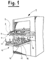
- FIG. 1 is a general schematic perspective view of an ejection station 1 of a press cut.
- This ejection station comprises an upper tool 2 which is, in the example chosen, in the form of a wooden board 3 provided with ejection needles 4.
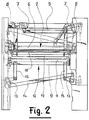
- the upper tool 2 is held in a support frame upper 5 which can slide like a drawer in slides, not shown, fixed on an upper cradle 6, movable vertically under the effect of a device with levers 7 and pulls 8 and 9 (see FIG. 2).
- the ejection station 1 also comprises a lower tool 10 held in a lower support frame 11 which can also slide in the manner of a drawer in slides, not shown, fixed on a lower cradle 12, movable vertically under the action of a device with levers 13 and drawbars 14 and 15 (see also Figure 2).
- the lower tool comprises several bars 16, of which only a few have been shown so as not to harm the clarity of the figure.
- a series of telescopic ejection needles 17 is mounted on these bars 16 opposite the ejection needles 4 of the upper tool 2.
- the ejection station 1 comprises a third element in the form of a perforated plate 18 mounted on a frame 19 which can also be extracted from the ejection station 1 in the manner of a drawer.
- the perforations of the plate 18 are produced so as to take account of the shape of the waste to be ejected and the ejection needles 4 and 17, arranged opposite one another, pinch the waste and push it through the perforations of the plate 18 when the sheet of cardboard to be worked is stopped in the ejection station.
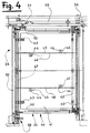
- Figure 3 is a schematic perspective view of an upper tool frame 20 comprising a front bar 21 and a rear bar 22 connected by two crosspieces 23 and 24 so as to form a rigid frame.
- the front and rear bars 21 and 22 are braced by two other crosspieces 25 and 26.
- the sheet to be worked arrives in the ejection station in the direction indicated by the arrow 27 and the frame carries upper tools 20 will be removed from this station, for example when changing tools, perpendicular to the direction of arrow 27.
- This figure also shows, schematically, the centering and locking of the tool holder frame 20.
- the front part of this frame 20, at the level of the front bar 21, is equipped with a guide stud 28 comprising a groove 29 in which a guide member 30 engages allowing the movement of the frame in the direction indicated by the double arrow 31.
- a locking stud 32 comprising a groove 33 and a bore 34 in which the centering and locking pigeon 61 comes s 'to hire.
- the rear part of the frame 20, at the rear bar 22, is equipped with another guide pad 35 having a groove 36 in which engages a guide member 37 allowing the movement of the frame 20 in the direction indicated by the double arrow 38.
- the rear part of the frame 20 has a support member 39 which is simply formed by guiding the frame in the slide 85.
- This arrangement of the guides, of the centering and locking the frame 20 provides excellent rigidity of the frame 20 when it is machine locked.
- the construction of the lower tool holder frame is made according to the same principle, with the only difference that the studs of guide 28 and 35 as well as the centering and locking stud 32 will be reversed so that the grooves 29, 33 and 36 are facing downwards from the tool holder frame.
- FIG 4 is a schematic plan view of the ejection board holder frame 40.
- the ejection board consists of a perforated plate 41, shown here without perforations corresponding to the locations of the waste to be ejected.
- This perforated plate 41 is fixed to a frame 42 by means of fixing lugs 43 and screws 44 screwed into brackets 45 fixed on adjustable support bars 46 bearing on the front transverse bar 47 of the frame 40 and on a crosspiece 48 , also adjustable, connecting the two longitudinal bars 49 and 50 which connect the front crossbar 47 to the rear crossbar 51 of the frame 40.
- the front crossbars 47 and rear 51 engage in slides 52 and 53 integral with a movable cradle 54 actuated by a pivoting lever 55.
- This lever 55 pivots around a point of rotation 56 located in the vicinity of the rear crossbar 51 under the effect of a control means which is not shown here.
- the movable cradle 54 is connected to the pivoting lever 55 by an adjustable centering member 57 and by a centering and locking device 58 which will be described in more detail with reference to FIGS. 11 and 12.
- FIG. 5 is a side view, in partial section, of a first locking and centering member 59 of an upper tool holder frame 20.
- This figure represents the front part of the tool holder frame 20 and in particular the front bar 21 when the latter is engaged in the slide 60 of the upper cradle 6.
- the first locking member and of centering 59 comprises a flexible rod 62, fixed at one of its ends, in a split stud 63 using two screws 64.
- the split stud 63 is integral with the slide 60 of the upper cradle 6.
- This stem flexible 62 passes through the upper part of the centering and locking pigeon 61 which has a countersink comprising two inclined planes 65 and 66 in opposition, the inclined planes being in the form of a roof.
- the centering and locking pigeon 61 is mounted in a bushing 74 fixed to an adjustment strip 75 provided at one of its ends with an adjustment stud 76 receiving a threaded rod 77 passing through an anchoring stud 78 fixed to the upper cradle 6.
- the nuts 79 mounted on the threaded rod 77 will therefore make it possible to adjust the desired position of the centering and locking pigeon 61 by causing the adjustment strip 75 to move, the latter being guided in an elongated slot 80 in which a cylindrical pin 81 engages.
- the other end of the flexible rod is equipped with a handle 67.
- the upper tool holder frame 20 is in the centered and locked position, that is to say that the conical part of the centering and locking pigeon 61 is engaged in the bore 34, thereby preventing any lateral extraction of this tool-holder frame 20.
- the latter is also held, at the part opposite the locking stud 32, by the guide member 30 which engages in the groove 29 of the guide pad 28.
- the guide member 30 is constituted by a guide pad 69 having a nose 70 having two inclined planes 71 and 72 (see FIG. 8) which will act jointly with the inclined sides 82 and 83 of the groove 29 of the guide pad 28 (see also FIG. 8) to ensure precise guidance of the tool holder frame 20.
- the guide pad 69 is fixed to the slide 60 of the upper cradle 6 using two screws 73.
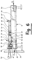
- FIG. 6 is a side view, in partial section, of a second locking and centering member 84 of an upper tool holder frame 20.
- This figure represents the rear part of the tool holder frame 20 and in particular the rear bar 22 when the latter is engaged in the slide 85 of the upper cradle 6.
- the second locking and centering member 84 comprises a flexible rod 86, fixed at one of its ends, in a split stud 87 at the using two screws 88.
- the split stud 87 is integral with the slide 85 of the upper cradle 6.
- This flexible rod 86 passes through the upper part of the centering and locking pigeon 89 which has a countersink comprising two inclined planes 90 and 91 in opposition, the inclined planes being in the form of a roof.
- the centering and locking pigeon 89 is mounted in a bushing 92 fixed on a setting strip 93 provided at one of its ends with an adjustment stud 94 receiving a threaded rod 95 passing through an anchoring stud 96 fixed to the upper cradle 6.
- the nuts 97 mounted on the threaded rod 95 will therefore make it possible to adjust the desired position of the centering and locking pigeon 89 by moving the adjusting strip 93, the latter being guided in an elongated slot 98 in which engages a cylindrical pin 99.
- the other end of the flexible rod 86 is equipped with a handle 100.
- the flexible rod 86 engages in a bayonet bracket 101 whose shape will be visible in FIG. 9 which will be described farther, the bayonet bracket 101 being fixed to the adjustment strip 93.
- the upper tool holder frame 20 is in the centered and locked position, that is to say that the conical part of the centering and locking pigeon 89 is engaged in the groove 36, thereby preventing any lateral extraction of this tool-carrying frame 20.
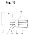
- the latter is also held, at the part opposite to the locking stud 35, by the support member 39 which acts against the inner faces of the slide 85 (see FIG. 10).
- the lower tool ejection frame will be produced in the same way and will also use a three-point centering and locking device.
- the construction being similar, it does not seem advisable to describe it in more detail because the description relating to the upper tool holder frame 20 can easily be transposed to this embodiment.
- FIG. 7 is a view along A of FIG. 5 which represents the manner in which the tool-carrying frame 20 as well as the first locking and centering member 59 are arranged relative to the upper cradle 6.
- FIG. 7 represents the manner in which the tool-carrying frame 20 as well as the first locking and centering member 59 are arranged relative to the upper cradle 6.
- Figure 8 is a view along B of Figure 5 showing how the tool holder frame 20 and the guide member 30 are disposed relative to the upper cradle 6 and how the guide member 30 is connected to the cradle upper by means of a plate 102.
- Figure 8 will also be made to the reference signs used when describing FIG. 5.
- FIG. 9 is a view along C of FIG. 6 which represents the way in which the tool-carrying frame 20 as well as the second locking and centering member 84 are arranged relative to the upper cradle 6.
- Figure 10 is a view along D of Figure 6 showing how the tool holder frame 20 and the guide member 30 are arranged relative to the upper cradle 6 and how is carried the support of the tool holder frame 20 in the upper cradle 6 by means of the slide 85.
- reference will also be made to the reference signs used when describing FIG. 6.
- Figure 11 is a side view of a centering and locking device 58 of an ejection board support frame 40 in which is mounted a perforated plate 41 and Figure 12 is a sectional view along XII-XII in Figure 11.
- this ejection board holder frame has only one centering and locking device 58.
- the ejection board holder frame 40 is integral of the movable cradle 54.
- a locking stud 104 is mounted on a counterpart 106 fixed to an attachment tab 105 of the movable cradle 54.
- the locking stud 104 has a threaded rod 107 engaging in a drilling of the counterpart 106.
- the position of the locking stud 104 can be adjusted by acting on the nuts 108 of the threaded rod 107 (see also FIG. 12).
- the locking stud 104 has a bore 109 in which the cylindrical part of the lock 110 engages.
- the lock 110 is mounted, so as to be able to slide, in a socket 111 driven into a support 112 secured to the board-carrying frame ejection 40.
- the bore which receives the sleeve 111 is closed at one of its ends against which a spring 113 is also supported guided in a bore 114 arranged in the upper end of the latch 110.
- the latch 110 is in addition provided with a control rod 115 whose cylindrical part 116 engages in a bayonet 117 machined in the support 112.
- the control rod 115 is moreover provided with a handle 118 by means of which it is possible, against the action of the spring 113, pass from a locked position, shown in FIG. 12, to an unlocked position 119 shown in phantom in FIG. 11.
Landscapes
- Engineering & Computer Science (AREA)
- Mechanical Engineering (AREA)
- Life Sciences & Earth Sciences (AREA)
- Forests & Forestry (AREA)
- Perforating, Stamping-Out Or Severing By Means Other Than Cutting (AREA)
- Mounting, Exchange, And Manufacturing Of Dies (AREA)
- Finish Polishing, Edge Sharpening, And Grinding By Specific Grinding Devices (AREA)
- Automatic Tool Replacement In Machine Tools (AREA)
Applications Claiming Priority (2)
| Application Number | Priority Date | Filing Date | Title |
|---|---|---|---|
| CH01395/94A CH689971A5 (fr) | 1994-05-04 | 1994-05-04 | Dispositif de centrage et de verrouillage d'un cadre porte-outils dans une presse de découpage. |
| CH1395/94 | 1994-05-04 |
Publications (2)
| Publication Number | Publication Date |
|---|---|
| EP0683003A1 true EP0683003A1 (de) | 1995-11-22 |
| EP0683003B1 EP0683003B1 (de) | 1999-03-31 |
Family
ID=4209430
Family Applications (1)
| Application Number | Title | Priority Date | Filing Date |
|---|---|---|---|
| EP95106523A Expired - Lifetime EP0683003B1 (de) | 1994-05-04 | 1995-04-29 | Vorrichtung zum Positionieren und Fixieren eines Werkzeugträgers in einer Schneidvorrichtung |
Country Status (11)
| Country | Link |
|---|---|
| US (1) | US5784939A (de) |
| EP (1) | EP0683003B1 (de) |
| JP (1) | JP2931541B2 (de) |
| KR (1) | KR0173043B1 (de) |
| CN (1) | CN1065167C (de) |
| AT (1) | ATE178242T1 (de) |
| AU (1) | AU686750B2 (de) |
| BR (1) | BR9501880A (de) |
| CH (1) | CH689971A5 (de) |
| DE (1) | DE69508646T2 (de) |
| ES (1) | ES2131721T3 (de) |
Cited By (2)
| Publication number | Priority date | Publication date | Assignee | Title |
|---|---|---|---|---|
| WO2004026545A1 (en) * | 2002-09-18 | 2004-04-01 | Blanking Systems, Inc. | Locator bracket for the lower frame assembly of a blanking tool |
| FR3000425A1 (fr) * | 2013-01-03 | 2014-07-04 | Louis Paul Mathian | Presse de decoupe de papier et carton |
Families Citing this family (18)
| Publication number | Priority date | Publication date | Assignee | Title |
|---|---|---|---|---|
| JP3022299B2 (ja) * | 1996-01-26 | 2000-03-15 | 株式会社日光製作所 | 自動平盤打抜機 |
| US6012369A (en) * | 1997-11-21 | 2000-01-11 | Abbey Etna Machine Company | Tube cut-off device having a die set removal apparatus |
| CH694086A5 (fr) * | 2000-05-16 | 2004-07-15 | Bobst Sa | Presse de façonnage. |
| TWI246452B (en) * | 2003-10-14 | 2006-01-01 | Bobst Sa | Blanking station of a diecutting press |
| US7360475B2 (en) * | 2004-04-08 | 2008-04-22 | Paolo Quercia | Stripping device for a press |
| US20050227846A1 (en) * | 2004-04-08 | 2005-10-13 | Paolo Quercia | Stripping device for a press |
| CN100382661C (zh) * | 2005-12-30 | 2008-04-16 | 珠海元盛电子科技股份有限公司 | 抽屉式模具 |
| DE202016102593U1 (de) * | 2016-05-13 | 2016-06-10 | Bobst Mex Sa | Vorrichtung zum Bearbeiten von Werkstückbögen |
| CA3021469C (en) * | 2016-05-13 | 2020-07-28 | Bobst Mex Sa | Method of aligning an upper and a lower changeable tool, and device for processing workpiece sheets |
| CN108582230B (zh) * | 2018-05-24 | 2023-08-01 | 浙江华岳包装机械有限公司 | 带自动清废功能的切纸机 |
| EP3608135B1 (de) * | 2018-08-09 | 2022-03-09 | Inalfa Roof Systems Group B.V. | Offene dachkonstruktion für ein fahrzeug und verfahren zur befestigung einer platte |
| CN109514626B (zh) * | 2018-12-21 | 2024-03-26 | 平湖市南桥箱包有限公司 | 一种防潮高弹性拉杆箱中拉杆的切割设备 |
| CN110340971A (zh) * | 2019-07-23 | 2019-10-18 | 浙江欧利特科技股份有限公司 | 模切烫印机清废下板框的调节机构 |
| CN114245770B (zh) * | 2019-08-16 | 2024-06-07 | 潘泰克Gs系统有限公司 | 用于平面压印机的工具板定位的设备 |
| CN110605741B (zh) * | 2019-10-10 | 2024-06-11 | 无锡帝朗光学材料科技有限公司 | 一种升降式切割机 |
| TWI810789B (zh) * | 2021-02-01 | 2023-08-01 | 瑞士商巴柏斯特麥克斯合資公司 | 板材加工工具、板材加工站與板材加工機 |
| CN114212007B (zh) * | 2022-01-06 | 2023-06-09 | 杭州申昊科技股份有限公司 | 一种刚性接触网锚段关节结构 |
| US11672386B1 (en) * | 2022-06-22 | 2023-06-13 | Boomhous Products, Inc. | Potty (toilet training) chair |
Citations (3)
| Publication number | Priority date | Publication date | Assignee | Title |
|---|---|---|---|---|
| FR2354882A1 (fr) * | 1976-06-16 | 1978-01-13 | Ichinose Shiro | Dispositif pour regler la position d'un ecran plan dans une machine automatique d'impression par serigraphie |
| US4627321A (en) * | 1985-12-10 | 1986-12-09 | Moore Scott B | Punch press machine including a workpiece positioning means with a quick change die holder, punch and stripper unit |
| US5072507A (en) * | 1990-10-30 | 1991-12-17 | The Lawrence Paper Company | Die changeover apparatus for box blank cutting machine |
Family Cites Families (11)
| Publication number | Priority date | Publication date | Assignee | Title |
|---|---|---|---|---|
| US447096A (en) * | 1891-02-24 | Pump attachment for windmills | ||
| US813613A (en) * | 1905-05-02 | 1906-02-27 | John R Boals | Pump-rod coupling. |
| US1026352A (en) * | 1910-04-21 | 1912-05-14 | William H Killen | Windmill-coupling. |
| US1150681A (en) * | 1913-03-03 | 1915-08-17 | Nellie G White | Sucker-rod clutch. |
| US1223833A (en) * | 1915-02-26 | 1917-04-24 | Ernest W Robbins | Attachment for coupling a pump to a windmill. |
| GB964902A (en) * | 1961-03-15 | 1964-07-29 | Maxam Inc | Quick release die and die carrier |
| CH530850A (fr) * | 1971-07-13 | 1972-11-30 | Bobst Fils Sa J | Presse à découper une matière en feuille |
| US4960026A (en) * | 1989-10-11 | 1990-10-02 | Emerson Electric Co. | Quick action band saw blade tensioning device |
| CH683681A5 (fr) * | 1990-04-26 | 1994-04-29 | Bobst Sa | Table pour la préparation d'outils de séparation des poses dans une machine de découpage de feuilles pour la production d'emballages. |
| DE4238449C1 (de) * | 1992-11-13 | 1994-03-24 | Georg Aigner | Anlaufleiste für eine Schutzhaube an Holzfräsmaschinen |
| US5338133A (en) * | 1993-03-05 | 1994-08-16 | Tornero Lino E | Lever clamp mechanism |
-
1994
- 1994-05-04 CH CH01395/94A patent/CH689971A5/fr not_active IP Right Cessation
-
1995
- 1995-04-29 DE DE69508646T patent/DE69508646T2/de not_active Expired - Lifetime
- 1995-04-29 EP EP95106523A patent/EP0683003B1/de not_active Expired - Lifetime
- 1995-04-29 ES ES95106523T patent/ES2131721T3/es not_active Expired - Lifetime
- 1995-04-29 AT AT95106523T patent/ATE178242T1/de not_active IP Right Cessation
- 1995-05-01 AU AU17762/95A patent/AU686750B2/en not_active Ceased
- 1995-05-03 BR BR9501880A patent/BR9501880A/pt not_active IP Right Cessation
- 1995-05-03 KR KR1019950010875A patent/KR0173043B1/ko not_active Expired - Fee Related
- 1995-05-04 CN CN95105220A patent/CN1065167C/zh not_active Expired - Lifetime
- 1995-05-08 JP JP7109655A patent/JP2931541B2/ja not_active Expired - Fee Related
-
1997
- 1997-01-27 US US08/791,461 patent/US5784939A/en not_active Expired - Lifetime
Patent Citations (3)
| Publication number | Priority date | Publication date | Assignee | Title |
|---|---|---|---|---|
| FR2354882A1 (fr) * | 1976-06-16 | 1978-01-13 | Ichinose Shiro | Dispositif pour regler la position d'un ecran plan dans une machine automatique d'impression par serigraphie |
| US4627321A (en) * | 1985-12-10 | 1986-12-09 | Moore Scott B | Punch press machine including a workpiece positioning means with a quick change die holder, punch and stripper unit |
| US5072507A (en) * | 1990-10-30 | 1991-12-17 | The Lawrence Paper Company | Die changeover apparatus for box blank cutting machine |
Cited By (3)
| Publication number | Priority date | Publication date | Assignee | Title |
|---|---|---|---|---|
| WO2004026545A1 (en) * | 2002-09-18 | 2004-04-01 | Blanking Systems, Inc. | Locator bracket for the lower frame assembly of a blanking tool |
| US6997364B2 (en) | 2002-09-18 | 2006-02-14 | Blanking Systems, Inc. | Locator bracket for the lower frame assembly of a blanking tool |
| FR3000425A1 (fr) * | 2013-01-03 | 2014-07-04 | Louis Paul Mathian | Presse de decoupe de papier et carton |
Also Published As
| Publication number | Publication date |
|---|---|
| DE69508646D1 (de) | 1999-05-06 |
| AU686750B2 (en) | 1998-02-12 |
| AU1776295A (en) | 1995-11-09 |
| CN1065167C (zh) | 2001-05-02 |
| KR950031490A (ko) | 1995-12-18 |
| JPH07299797A (ja) | 1995-11-14 |
| US5784939A (en) | 1998-07-28 |
| DE69508646T2 (de) | 1999-07-29 |
| ES2131721T3 (es) | 1999-08-01 |
| CH689971A5 (fr) | 2000-02-29 |
| BR9501880A (pt) | 1995-11-28 |
| KR0173043B1 (ko) | 1999-02-18 |
| CN1117431A (zh) | 1996-02-28 |
| ATE178242T1 (de) | 1999-04-15 |
| JP2931541B2 (ja) | 1999-08-09 |
| EP0683003B1 (de) | 1999-03-31 |
Similar Documents
| Publication | Publication Date | Title |
|---|---|---|
| EP0683003B1 (de) | Vorrichtung zum Positionieren und Fixieren eines Werkzeugträgers in einer Schneidvorrichtung | |
| EP0599670B1 (de) | Portale Fräs- und Bohrmaschine | |
| CH691035A5 (fr) | Outil pour machine de découpe d'éléments en plaque, et équipement associé. | |
| CH617886A5 (de) | ||
| CH667233A5 (fr) | Installation de decoupage aux filets. | |
| EP0389751A1 (de) | Lateral-Justiervorrichtung für Schlitzmaschinen | |
| EP1155791B1 (de) | Schneidpresse | |
| EP1153871B1 (de) | Auslegerstation einer Formpresse und Werkzeugsatz für eine solche Station | |
| EP0278879B1 (de) | Maschine zur automatischen Herstellung von Fleisch- und/oder Gemüsespiessen | |
| FR2473373A1 (fr) | Perceuse perfectionnee a assujettissement automatique de la piece | |
| FR2527123A1 (fr) | Dispositif pour confectionner les matrices d'une presse a platines | |
| EP0741096A2 (de) | Transportvorrichtung für metallisiertes Bahnmaterial | |
| EP1095745A2 (de) | Verfahren zur Vorbereitung von formgebenden Werkzeugen, Einstelltisch zur Ausführung des Verfahrens und Teilesatz zur Vorbereitung eines oberen Ausbrechwerkzeuges | |
| EP0020996B1 (de) | Band- und Typenträgerkassette tragender Wagen | |
| FR2547232A1 (fr) | Rectifieuse | |
| EP0683004B1 (de) | Wechselvorrichtung für die Werkzeuge einer Schneidvorrichtung | |
| EP3820265B1 (de) | Verfahren und vorrichtung zum schneiden eines radialen elektronischen bauteils | |
| FR2680771A1 (fr) | Dispositif de reunion d'un reste de pile et d'une pile principale de feuilles. | |
| EP0195722B1 (de) | Ein- und Ausziehvorrichtung für elektronische Karten | |
| FR2560080A1 (fr) | Poinconneuse destinee notamment a la perforation ou a la decoupe de coffrets ou de boitiers | |
| EP2475516B1 (de) | Presse mit einer werkzeugzentrierenden vorrichtung und verfahren zur vorpositionierung und befestigung eines werkzeugs auf eine pressplatte | |
| BE859478A (fr) | Table pour la preparation a la coupe de panneaux de tissus | |
| FR2845021A1 (fr) | Presse a decouper | |
| BE358659A (de) | ||
| CH342816A (fr) | Machine-outil comprenant un dispositif de transfert |
Legal Events
| Date | Code | Title | Description |
|---|---|---|---|
| PUAI | Public reference made under article 153(3) epc to a published international application that has entered the european phase |
Free format text: ORIGINAL CODE: 0009012 |
|
| 17P | Request for examination filed |
Effective date: 19950429 |
|
| AK | Designated contracting states |
Kind code of ref document: A1 Designated state(s): AT BE DE ES FR GB IT |
|
| 17Q | First examination report despatched |
Effective date: 19970416 |
|
| GRAG | Despatch of communication of intention to grant |
Free format text: ORIGINAL CODE: EPIDOS AGRA |
|
| GRAG | Despatch of communication of intention to grant |
Free format text: ORIGINAL CODE: EPIDOS AGRA |
|
| GRAH | Despatch of communication of intention to grant a patent |
Free format text: ORIGINAL CODE: EPIDOS IGRA |
|
| GRAH | Despatch of communication of intention to grant a patent |
Free format text: ORIGINAL CODE: EPIDOS IGRA |
|
| GRAA | (expected) grant |
Free format text: ORIGINAL CODE: 0009210 |
|
| AK | Designated contracting states |
Kind code of ref document: B1 Designated state(s): AT BE DE ES FR GB IT |
|
| REF | Corresponds to: |
Ref document number: 178242 Country of ref document: AT Date of ref document: 19990415 Kind code of ref document: T |
|
| GBT | Gb: translation of ep patent filed (gb section 77(6)(a)/1977) |
Effective date: 19990408 |
|
| REF | Corresponds to: |
Ref document number: 69508646 Country of ref document: DE Date of ref document: 19990506 |
|
| REG | Reference to a national code |
Ref country code: ES Ref legal event code: FG2A Ref document number: 2131721 Country of ref document: ES Kind code of ref document: T3 |
|
| PLBE | No opposition filed within time limit |
Free format text: ORIGINAL CODE: 0009261 |
|
| STAA | Information on the status of an ep patent application or granted ep patent |
Free format text: STATUS: NO OPPOSITION FILED WITHIN TIME LIMIT |
|
| 26N | No opposition filed | ||
| REG | Reference to a national code |
Ref country code: GB Ref legal event code: IF02 |
|
| PGFP | Annual fee paid to national office [announced via postgrant information from national office to epo] |
Ref country code: BE Payment date: 20070312 Year of fee payment: 13 |
|
| PGFP | Annual fee paid to national office [announced via postgrant information from national office to epo] |
Ref country code: AT Payment date: 20070403 Year of fee payment: 13 |
|
| PGFP | Annual fee paid to national office [announced via postgrant information from national office to epo] |
Ref country code: GB Payment date: 20070416 Year of fee payment: 13 |
|
| BERE | Be: lapsed |
Owner name: S.A. *BOBST Effective date: 20080430 |
|
| GBPC | Gb: european patent ceased through non-payment of renewal fee |
Effective date: 20080429 |
|
| PG25 | Lapsed in a contracting state [announced via postgrant information from national office to epo] |
Ref country code: AT Free format text: LAPSE BECAUSE OF NON-PAYMENT OF DUE FEES Effective date: 20080429 |
|
| PG25 | Lapsed in a contracting state [announced via postgrant information from national office to epo] |
Ref country code: BE Free format text: LAPSE BECAUSE OF NON-PAYMENT OF DUE FEES Effective date: 20080430 |
|
| PG25 | Lapsed in a contracting state [announced via postgrant information from national office to epo] |
Ref country code: GB Free format text: LAPSE BECAUSE OF NON-PAYMENT OF DUE FEES Effective date: 20080429 |
|
| PGFP | Annual fee paid to national office [announced via postgrant information from national office to epo] |
Ref country code: DE Payment date: 20120502 Year of fee payment: 18 |
|
| PGFP | Annual fee paid to national office [announced via postgrant information from national office to epo] |
Ref country code: FR Payment date: 20120424 Year of fee payment: 18 |
|
| PGFP | Annual fee paid to national office [announced via postgrant information from national office to epo] |
Ref country code: IT Payment date: 20120423 Year of fee payment: 18 |
|
| PGFP | Annual fee paid to national office [announced via postgrant information from national office to epo] |
Ref country code: ES Payment date: 20120510 Year of fee payment: 18 |
|
| PG25 | Lapsed in a contracting state [announced via postgrant information from national office to epo] |
Ref country code: DE Free format text: LAPSE BECAUSE OF NON-PAYMENT OF DUE FEES Effective date: 20131101 |
|
| REG | Reference to a national code |
Ref country code: FR Ref legal event code: ST Effective date: 20131231 |
|
| REG | Reference to a national code |
Ref country code: DE Ref legal event code: R119 Ref document number: 69508646 Country of ref document: DE Effective date: 20131101 |
|
| PG25 | Lapsed in a contracting state [announced via postgrant information from national office to epo] |
Ref country code: IT Free format text: LAPSE BECAUSE OF NON-PAYMENT OF DUE FEES Effective date: 20130429 Ref country code: FR Free format text: LAPSE BECAUSE OF NON-PAYMENT OF DUE FEES Effective date: 20130430 |
|
| REG | Reference to a national code |
Ref country code: ES Ref legal event code: FD2A Effective date: 20140609 |
|
| PG25 | Lapsed in a contracting state [announced via postgrant information from national office to epo] |
Ref country code: ES Free format text: LAPSE BECAUSE OF NON-PAYMENT OF DUE FEES Effective date: 20130430 |