EP0682401A1 - Dispositif pour la limitation de la pente de la tension de sortie d'un convertisseur auto-commuté - Google Patents
Dispositif pour la limitation de la pente de la tension de sortie d'un convertisseur auto-commuté Download PDFInfo
- Publication number
- EP0682401A1 EP0682401A1 EP95106488A EP95106488A EP0682401A1 EP 0682401 A1 EP0682401 A1 EP 0682401A1 EP 95106488 A EP95106488 A EP 95106488A EP 95106488 A EP95106488 A EP 95106488A EP 0682401 A1 EP0682401 A1 EP 0682401A1
- Authority
- EP
- European Patent Office
- Prior art keywords
- induction machine
- capacitance network
- voltage
- strands
- current
- Prior art date
- Legal status (The legal status is an assumption and is not a legal conclusion. Google has not performed a legal analysis and makes no representation as to the accuracy of the status listed.)
- Granted
Links
Images
Classifications
-
- H—ELECTRICITY
- H02—GENERATION; CONVERSION OR DISTRIBUTION OF ELECTRIC POWER
- H02M—APPARATUS FOR CONVERSION BETWEEN AC AND AC, BETWEEN AC AND DC, OR BETWEEN DC AND DC, AND FOR USE WITH MAINS OR SIMILAR POWER SUPPLY SYSTEMS; CONVERSION OF DC OR AC INPUT POWER INTO SURGE OUTPUT POWER; CONTROL OR REGULATION THEREOF
- H02M7/00—Conversion of ac power input into dc power output; Conversion of dc power input into ac power output
- H02M7/42—Conversion of dc power input into ac power output without possibility of reversal
- H02M7/44—Conversion of dc power input into ac power output without possibility of reversal by static converters
- H02M7/48—Conversion of dc power input into ac power output without possibility of reversal by static converters using discharge tubes with control electrode or semiconductor devices with control electrode
- H02M7/53—Conversion of dc power input into ac power output without possibility of reversal by static converters using discharge tubes with control electrode or semiconductor devices with control electrode using devices of a triode or transistor type requiring continuous application of a control signal
- H02M7/537—Conversion of dc power input into ac power output without possibility of reversal by static converters using discharge tubes with control electrode or semiconductor devices with control electrode using devices of a triode or transistor type requiring continuous application of a control signal using semiconductor devices only, e.g. single switched pulse inverters
- H02M7/5387—Conversion of dc power input into ac power output without possibility of reversal by static converters using discharge tubes with control electrode or semiconductor devices with control electrode using devices of a triode or transistor type requiring continuous application of a control signal using semiconductor devices only, e.g. single switched pulse inverters in a bridge configuration
-
- H—ELECTRICITY
- H02—GENERATION; CONVERSION OR DISTRIBUTION OF ELECTRIC POWER
- H02M—APPARATUS FOR CONVERSION BETWEEN AC AND AC, BETWEEN AC AND DC, OR BETWEEN DC AND DC, AND FOR USE WITH MAINS OR SIMILAR POWER SUPPLY SYSTEMS; CONVERSION OF DC OR AC INPUT POWER INTO SURGE OUTPUT POWER; CONTROL OR REGULATION THEREOF
- H02M1/00—Details of apparatus for conversion
- H02M1/12—Arrangements for reducing harmonics from ac input or output
-
- H—ELECTRICITY
- H02—GENERATION; CONVERSION OR DISTRIBUTION OF ELECTRIC POWER
- H02P—CONTROL OR REGULATION OF ELECTRIC MOTORS, ELECTRIC GENERATORS OR DYNAMO-ELECTRIC CONVERTERS; CONTROLLING TRANSFORMERS, REACTORS OR CHOKE COILS
- H02P5/00—Arrangements specially adapted for regulating or controlling the speed or torque of two or more electric motors
- H02P5/74—Arrangements specially adapted for regulating or controlling the speed or torque of two or more electric motors controlling two or more ac dynamo-electric motors
Definitions
- the present invention is in the field of frequency converters or inverters, which have been increasingly used for speed control of induction machines for several years. So-called U inverters with a DC voltage intermediate circuit are predominantly used. The latter forms a DC voltage from the normally constant mains voltage. This is switched in the inverter by means of power semiconductor switches, whereby the desired three-phase three-phase network with variable voltage and frequency is provided.
- the invention now relates to a device for limiting the rate of change of the output-side voltage of a converter which is self-controlled via a DC voltage intermediate circuit and which has output terminals for the connection of at least one induction machine and an inductance arranged between each output terminal and the at least one induction machine.
- the inductors are so-called current rise limiting chokes, which are followed by three diode branches, each with two diodes.
- the current rise limiting chokes are each connected to the line piece connecting the cathode connection of one diode to the anode connection of the other diode of a diode branch.
- this known device can noticeably reduce some of the problems listed above, in particular the stress on the insulation of the connected induction machine due to steep voltage pulses or the stress on the power semiconductors due to the connecting cable, it is practically ineffective with regard to other problems. This is due to the fact that this device essentially only acts on the symmetrical voltages, that is to say on the voltages between the live lines, and practically does not influence the asymmetrical voltages.
- the invention is intended to provide a device of the type mentioned which acts both on symmetrical and on asymmetrical interference voltages and thereby eliminates or at least significantly reduces the problems mentioned at the outset.
- the device according to the invention reduces the rising and falling edges of the voltage pulses generated by the converter, as a result of which the problems with the stress on the insulation of the induction machines are reduced to a reasonable degree. At the same time, it affects the asymmetrical voltages with respect to the earth potential, whereby the disturbances caused by these asymmetrical voltages are also eliminated or at least largely reduced.
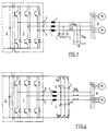
- inverter or frequency converter 1 provided for speed count control of induction machines, which is connected to a DC link 2 symbolized by a capacitor. This is fed by a mains rectifier (not shown) connected to the supply network with a usually constant voltage and constant frequency.
- the converter 1 switches the DC voltage of the DC voltage intermediate circuit 2 by means of power semiconductor switches and provides the desired three-phase three-phase network with variable frequency and voltage at its output terminals 3 for the connected induction machines 4 (e.g. motors M). If this description refers to induction machines or induction machines, then both, both a single machine and a machine group, are meant.
- FIG. 2 shows a theoretically possible variant that also largely reduces the asymmetrical voltages and thus could largely eliminate or reduce all the disadvantageous properties of the known converters discussed above.
- two capacitances C connected in a star are connected to each inductance L, and the star points are each connected to one pole of the intermediate circuit voltage of the converter 1.
- this circuit both sinusoidal, symmetrical voltages can be generated and the asymmetrical voltages can be limited in terms of their rise and fall times.
- the unbalanced currents I us in the return to the DC link 2 must be kept low so as not to put additional stress on the power semiconductors. Again, relatively high inductance values were required, which would lead to the problems already discussed in connection with FIG. 1.
- FIG. 2 avoids all of the disadvantages listed, but the practical implementation of this exemplary embodiment can fail due to economic and technical difficulties.
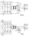
- FIGS. 3 and 4 show technically and economically feasible proposals for solving the problem.
- a first inductor L 1 and a second inductor L 2 is connected between each output terminal 3 of the converter 1 and the induction machine 4, the order of the two inductors not having an influence.
- the two inductors of which the first inductor L 1 is a so-called largely linear series choke and the second inductor L 2 is a current-compensated choke, is followed by a capacitance network CN with three strands, each of which consists of two capacitors C s connected in series.
- Each of the live lines between the inductors and the induction machine 4 is led to the center of one of the strands of the capacitance network.
- connection ends of the strands of the capacitance network CN are led to the positive or negative connection 5 or 6 of the DC voltage intermediate circuit 2.
- Each first inductor L 1 forms, together with the two capacitors C s of the line connected downstream, the LC low-pass filter required for generating the sinusoidal voltage between the live lines to the induction machine 4. As shown, this is connected to the DC link 2.
- a particular advantage of these current-compensated inductors or chokes is that, with a relatively small construction volume, high inductance values can be achieved, the size of the inductor naturally having to be designed for the asymmetrical currents that occur. Since these current-compensated chokes only generate negligible voltage drops for normal operating current, can be created by suitable dimensioning of a first inductance L 1 and the respective capacitors C s connected to this LC low-pass filter, which is effective for all the above-mentioned disadvantageous problems.
- FIG. 4 shows a further exemplary embodiment of a circuit for a technically and economically feasible solution to the problems mentioned.
- a first inductor (linear series choke) L 1 and a second inductor (current-compensated choke) L 2 which is followed by a capacitance network CN ' .
- a ⁇ connection of the capacitance network CN with connection of one or three capacitors to ground potential also results in an equivalent solution.
- capacitors C f can also be connected from the DC voltage intermediate circuit 2 to the ground potential in order to reduce radio interference suppression problems.
- asymmetrical currents can flow through the capacitors C s , C e and C f .
Landscapes
- Engineering & Computer Science (AREA)
- Power Engineering (AREA)
- Power Conversion In General (AREA)
- Inverter Devices (AREA)
- Dc-Dc Converters (AREA)
- Control Of Eletrric Generators (AREA)
Applications Claiming Priority (2)
| Application Number | Priority Date | Filing Date | Title |
|---|---|---|---|
| CH01462/94A CH693523A5 (de) | 1994-05-11 | 1994-05-11 | Einrichtung zur Begrenzung der Aenderungsgeschwindigkeit der ausgangsseitigen Spannung eines selbstgeführten mehrphasigen Umrichters. |
| CH1462/94 | 1994-05-11 |
Publications (2)
| Publication Number | Publication Date |
|---|---|
| EP0682401A1 true EP0682401A1 (fr) | 1995-11-15 |
| EP0682401B1 EP0682401B1 (fr) | 1998-05-27 |
Family
ID=4211045
Family Applications (1)
| Application Number | Title | Priority Date | Filing Date |
|---|---|---|---|
| EP95106488A Revoked EP0682401B1 (fr) | 1994-05-11 | 1995-04-28 | Dispositif pour la limitation de la pente de la tension de sortie d'un convertisseur auto-commuté |
Country Status (4)
| Country | Link |
|---|---|
| EP (1) | EP0682401B1 (fr) |
| AT (1) | ATE166753T1 (fr) |
| CH (1) | CH693523A5 (fr) |
| DE (1) | DE59502313D1 (fr) |
Cited By (7)
| Publication number | Priority date | Publication date | Assignee | Title |
|---|---|---|---|---|
| DE19637290A1 (de) * | 1996-09-13 | 1998-03-19 | Asea Brown Boveri | Stromrichterschaltungsanordnung mit lastseitigem Filter |
| DE19736786A1 (de) * | 1997-08-23 | 1999-02-25 | Asea Brown Boveri | U-Umrichter |
| DE19814059A1 (de) * | 1998-03-30 | 1999-10-07 | Asea Brown Boveri | Lastseitige Filteranordnung für eine Stromrichter-Schaltungsanordnung |
| WO2002084851A1 (fr) * | 2001-04-11 | 2002-10-24 | Abb Ab | Convertisseur de source de tension |
| EP1296441A1 (fr) * | 2001-09-25 | 2003-03-26 | ABB Schweiz AG | Système de production d'énergie |
| DE102004004627A1 (de) * | 2004-01-29 | 2005-08-18 | Siemens Ag | Schaltungsanordnung zur Reduzierung symmetrischer uns asymetrischer Spannungen |
| EP2367272A3 (fr) * | 2010-02-25 | 2017-06-21 | Kostal Industrie Elektrik GmbH | Onduleur |
Families Citing this family (6)
| Publication number | Priority date | Publication date | Assignee | Title |
|---|---|---|---|---|
| DE102005045554B3 (de) * | 2005-09-23 | 2007-04-26 | Siemens Ag | Filter zur Filterung von Störströmen |
| DE102008026869B4 (de) | 2008-06-05 | 2014-11-20 | Siemens Aktiengesellschaft | Verlustbehaftetes dreiphasiges Tiefpassfilter |
| DE102008031296A1 (de) | 2008-07-02 | 2009-08-20 | Siemens Aktiengesellschaft | Drosselspuleneinrichtung für einen Filterschaltkreis sowie Verwendung einer solchen und Filterschaltkreis |
| DE102009031547B3 (de) * | 2009-07-02 | 2010-10-21 | Siemens Aktiengesellschaft | Verfahren zur Steuerung eines lastseitigen Stromrichters |
| DE102010047338B4 (de) | 2010-10-01 | 2016-07-21 | Audi Ag | Kraftfahrzeug mit Schaltungsanordnung sowie Verfahren zum Betreiben eines solchen Kraftfahrzeugs |
| DE102010047994A1 (de) | 2010-10-08 | 2012-04-12 | Audi Ag | Anordnung, insbesondere in einem Kraftfahrzeug |
Citations (8)
| Publication number | Priority date | Publication date | Assignee | Title |
|---|---|---|---|---|
| DE3318480A1 (de) * | 1983-05-18 | 1984-11-22 | Licentia Gmbh | Thyristorgeregelter gleichrichter mit gutem dynamischen verhalten bei teillast |
| JPS60106370A (ja) * | 1983-11-15 | 1985-06-11 | Fuji Electric Co Ltd | Vvvfインバ−タ |
| JPS62171462A (ja) * | 1986-01-23 | 1987-07-28 | Fuji Electric Co Ltd | 静止型電力変換装置の3相ノイズフイルタ |
| JPS6474070A (en) * | 1987-09-11 | 1989-03-20 | Mitsubishi Electric Corp | Leak current reducing circuit |
| JPH0236795A (ja) * | 1988-07-22 | 1990-02-06 | Mitsubishi Electric Corp | インバータの漏電防止装置 |
| DE4135680A1 (de) * | 1991-10-30 | 1993-05-06 | Andreas Prof. Dr.-Ing.Habil. 7000 Stuttgart De Boehringer | Einrichtung zur begrenzung der aenderungsgeschwindigkeiten von ausgangsgroessen dreiphasiger, selbstgefuehrter wechselrichter mit gleichspannungszwischenkreis |
| DE9307806U1 (de) * | 1993-05-24 | 1993-08-26 | Siemens Ag | Umrichter-Ausgangsfilter |
| JPH0686563A (ja) * | 1992-09-01 | 1994-03-25 | Mitsubishi Electric Corp | 電力変換装置 |
-
1994
- 1994-05-11 CH CH01462/94A patent/CH693523A5/de not_active IP Right Cessation
-
1995
- 1995-04-28 DE DE59502313T patent/DE59502313D1/de not_active Revoked
- 1995-04-28 AT AT95106488T patent/ATE166753T1/de not_active IP Right Cessation
- 1995-04-28 EP EP95106488A patent/EP0682401B1/fr not_active Revoked
Patent Citations (8)
| Publication number | Priority date | Publication date | Assignee | Title |
|---|---|---|---|---|
| DE3318480A1 (de) * | 1983-05-18 | 1984-11-22 | Licentia Gmbh | Thyristorgeregelter gleichrichter mit gutem dynamischen verhalten bei teillast |
| JPS60106370A (ja) * | 1983-11-15 | 1985-06-11 | Fuji Electric Co Ltd | Vvvfインバ−タ |
| JPS62171462A (ja) * | 1986-01-23 | 1987-07-28 | Fuji Electric Co Ltd | 静止型電力変換装置の3相ノイズフイルタ |
| JPS6474070A (en) * | 1987-09-11 | 1989-03-20 | Mitsubishi Electric Corp | Leak current reducing circuit |
| JPH0236795A (ja) * | 1988-07-22 | 1990-02-06 | Mitsubishi Electric Corp | インバータの漏電防止装置 |
| DE4135680A1 (de) * | 1991-10-30 | 1993-05-06 | Andreas Prof. Dr.-Ing.Habil. 7000 Stuttgart De Boehringer | Einrichtung zur begrenzung der aenderungsgeschwindigkeiten von ausgangsgroessen dreiphasiger, selbstgefuehrter wechselrichter mit gleichspannungszwischenkreis |
| JPH0686563A (ja) * | 1992-09-01 | 1994-03-25 | Mitsubishi Electric Corp | 電力変換装置 |
| DE9307806U1 (de) * | 1993-05-24 | 1993-08-26 | Siemens Ag | Umrichter-Ausgangsfilter |
Non-Patent Citations (5)
| Title |
|---|
| PATENT ABSTRACTS OF JAPAN vol. 12, no. 13 (E - 573) 14 January 1988 (1988-01-14) * |
| PATENT ABSTRACTS OF JAPAN vol. 13, no. 295 (E - 783) 7 July 1989 (1989-07-07) * |
| PATENT ABSTRACTS OF JAPAN vol. 14, no. 190 (E - 918) 18 April 1990 (1990-04-18) * |
| PATENT ABSTRACTS OF JAPAN vol. 18, no. 345 (E - 1571) 29 June 1994 (1994-06-29) * |
| PATENT ABSTRACTS OF JAPAN vol. 9, no. 258 (E - 350) 16 October 1985 (1985-10-16) * |
Cited By (10)
| Publication number | Priority date | Publication date | Assignee | Title |
|---|---|---|---|---|
| DE19637290A1 (de) * | 1996-09-13 | 1998-03-19 | Asea Brown Boveri | Stromrichterschaltungsanordnung mit lastseitigem Filter |
| DE19736786A1 (de) * | 1997-08-23 | 1999-02-25 | Asea Brown Boveri | U-Umrichter |
| US5999423A (en) * | 1997-08-23 | 1999-12-07 | Asea Brown Boveri Ag | Voltage converter with filter arrangement |
| DE19814059A1 (de) * | 1998-03-30 | 1999-10-07 | Asea Brown Boveri | Lastseitige Filteranordnung für eine Stromrichter-Schaltungsanordnung |
| US6160442A (en) * | 1998-03-30 | 2000-12-12 | Asea Brown Boveri Ag | Load-side filter arrangement for a converter circuit arrangement |
| WO2002084851A1 (fr) * | 2001-04-11 | 2002-10-24 | Abb Ab | Convertisseur de source de tension |
| EP1296441A1 (fr) * | 2001-09-25 | 2003-03-26 | ABB Schweiz AG | Système de production d'énergie |
| US6774608B2 (en) | 2001-09-25 | 2004-08-10 | Abb Schweiz Ag | Turbine driven power generating device having DC voltage intermediate circuit and star connected filter capacitors |
| DE102004004627A1 (de) * | 2004-01-29 | 2005-08-18 | Siemens Ag | Schaltungsanordnung zur Reduzierung symmetrischer uns asymetrischer Spannungen |
| EP2367272A3 (fr) * | 2010-02-25 | 2017-06-21 | Kostal Industrie Elektrik GmbH | Onduleur |
Also Published As
| Publication number | Publication date |
|---|---|
| DE59502313D1 (de) | 1998-07-02 |
| CH693523A5 (de) | 2003-09-15 |
| ATE166753T1 (de) | 1998-06-15 |
| EP0682401B1 (fr) | 1998-05-27 |
Similar Documents
| Publication | Publication Date | Title |
|---|---|---|
| DE102008014898B4 (de) | Verfahren zur Steuerung eines mehrphasigen Stromrichters mit verteilten Energiespeichern bei niedrigen Ausgangsfrequenzen | |
| EP1040555B1 (fr) | Ensemble circuit convertisseur de courant presentant un circuit intermediaire a tension continue | |
| DE10143279B4 (de) | Frequenzumrichter | |
| DE112011101193B4 (de) | Leckstrom-Reduzierungsvorrichtung | |
| WO2003090331A2 (fr) | Alimentation electrique dotee d'un convertisseur direct | |
| EP0682402B1 (fr) | Dispositif pour la limitation de la pente des grandeurs de sortie d'un convertisseur auto-commuté à circuit intermédiaire à tension continue | |
| EP0682401B1 (fr) | Dispositif pour la limitation de la pente de la tension de sortie d'un convertisseur auto-commuté | |
| EP1069673B1 (fr) | Filtre réseau | |
| EP1220431A1 (fr) | Amortissement des surhaussements de résonance d'un moteur électrique alimenté par un convertisseur avec circuit intermédiaire de tension | |
| EP1211788A1 (fr) | Amortissement des surhaussements de résonance d'un moteur électrique alimenté par un convertisseur avec circuit intermédiaire de tension | |
| EP0682395B1 (fr) | Dispositif pour limitation de la vitesse de changement des courants et tensions entre conducteurs ou vers la terre et procédé l'utilisant | |
| EP3513475B1 (fr) | Système servant à transmettre une puissance électrique comprenant une unité de filtrage | |
| WO2017016692A1 (fr) | Dispositif pour éviter les courants de palier dommageables | |
| EP0743744A2 (fr) | Convertisseur de courant | |
| DE10215236C1 (de) | Vorrichtung zur induktiven Übertragung elektrischer Energie | |
| WO2018113926A1 (fr) | Convertisseur | |
| DE102009026479B4 (de) | Leistungshalbleitermodul mit verringerter Oszillationsneigung | |
| DE102015003225A1 (de) | Wechselrichter | |
| DE4430078A1 (de) | Schaltungsanordnung zur Vermeidung von Schaltverlusten eines Zweigpaares eines selbstgeführten Stromrichters mit eingeprägter Zwischenkreisgleichspannung | |
| DE19853693A1 (de) | Einrichtung zur Verhinderung von Überspannungen auf den Ausgangsleitungen eines selbstgeführten Umrichters | |
| EP0819563A2 (fr) | Convertisseur de puissance | |
| DE19952886A1 (de) | Mehrfachstromrichter | |
| DE102020000128A1 (de) | Antriebssystem, aufweisend einen ersten Verband und einen zweiten Verband | |
| EP3944483A1 (fr) | Circuit redresseur actif et son application dans une machine synchrone | |
| EP2713499A1 (fr) | Dispositif d'alimentation en énergie avec connexion symétrique d'une source de courant continu à un point neutre relié à la terre d'un réseau triphasé |
Legal Events
| Date | Code | Title | Description |
|---|---|---|---|
| PUAI | Public reference made under article 153(3) epc to a published international application that has entered the european phase |
Free format text: ORIGINAL CODE: 0009012 |
|
| AK | Designated contracting states |
Kind code of ref document: A1 Designated state(s): AT BE DE DK FR GB IE IT NL |
|
| 17P | Request for examination filed |
Effective date: 19960322 |
|
| 17Q | First examination report despatched |
Effective date: 19970415 |
|
| GRAG | Despatch of communication of intention to grant |
Free format text: ORIGINAL CODE: EPIDOS AGRA |
|
| GRAG | Despatch of communication of intention to grant |
Free format text: ORIGINAL CODE: EPIDOS AGRA |
|
| GRAH | Despatch of communication of intention to grant a patent |
Free format text: ORIGINAL CODE: EPIDOS IGRA |
|
| GRAH | Despatch of communication of intention to grant a patent |
Free format text: ORIGINAL CODE: EPIDOS IGRA |
|
| GRAA | (expected) grant |
Free format text: ORIGINAL CODE: 0009210 |
|
| TPAD | Observations filed by third parties |
Free format text: ORIGINAL CODE: EPIDOS TIPA |
|
| AK | Designated contracting states |
Kind code of ref document: B1 Designated state(s): AT BE DE DK FR GB IE IT NL |
|
| PG25 | Lapsed in a contracting state [announced via postgrant information from national office to epo] |
Ref country code: NL Free format text: LAPSE BECAUSE OF FAILURE TO SUBMIT A TRANSLATION OF THE DESCRIPTION OR TO PAY THE FEE WITHIN THE PRESCRIBED TIME-LIMIT Effective date: 19980527 Ref country code: IT Free format text: LAPSE BECAUSE OF FAILURE TO SUBMIT A TRANSLATION OF THE DESCRIPTION OR TO PAY THE FEE WITHIN THE PRESCRIBED TIME-LIMIT;WARNING: LAPSES OF ITALIAN PATENTS WITH EFFECTIVE DATE BEFORE 2007 MAY HAVE OCCURRED AT ANY TIME BEFORE 2007. THE CORRECT EFFECTIVE DATE MAY BE DIFFERENT FROM THE ONE RECORDED. Effective date: 19980527 |
|
| REF | Corresponds to: |
Ref document number: 166753 Country of ref document: AT Date of ref document: 19980615 Kind code of ref document: T |
|
| REF | Corresponds to: |
Ref document number: 59502313 Country of ref document: DE Date of ref document: 19980702 |
|
| GBT | Gb: translation of ep patent filed (gb section 77(6)(a)/1977) |
Effective date: 19980611 |
|
| ET | Fr: translation filed | ||
| REG | Reference to a national code |
Ref country code: IE Ref legal event code: FG4D Free format text: GERMAN |
|
| PG25 | Lapsed in a contracting state [announced via postgrant information from national office to epo] |
Ref country code: DK Free format text: LAPSE BECAUSE OF FAILURE TO SUBMIT A TRANSLATION OF THE DESCRIPTION OR TO PAY THE FEE WITHIN THE PRESCRIBED TIME-LIMIT Effective date: 19980827 |
|
| NLV1 | Nl: lapsed or annulled due to failure to fulfill the requirements of art. 29p and 29m of the patents act | ||
| PLBQ | Unpublished change to opponent data |
Free format text: ORIGINAL CODE: EPIDOS OPPO |
|
| PLBI | Opposition filed |
Free format text: ORIGINAL CODE: 0009260 |
|
| 26 | Opposition filed |
Opponent name: SIEMENS AKTIENGESELLSCHAFT, BERLIN UND MUENCHEN Effective date: 19990208 |
|
| PLBF | Reply of patent proprietor to notice(s) of opposition |
Free format text: ORIGINAL CODE: EPIDOS OBSO |
|
| PLAB | Opposition data, opponent's data or that of the opponent's representative modified |
Free format text: ORIGINAL CODE: 0009299OPPO |
|
| RAP2 | Party data changed (patent owner data changed or rights of a patent transferred) |
Owner name: SCHAFFNER EMV AG |
|
| R26 | Opposition filed (corrected) |
Opponent name: SIEMENS AG Effective date: 19990208 |
|
| PLBF | Reply of patent proprietor to notice(s) of opposition |
Free format text: ORIGINAL CODE: EPIDOS OBSO |
|
| REG | Reference to a national code |
Ref country code: GB Ref legal event code: IF02 |
|
| PLCK | Communication despatched that opposition was rejected |
Free format text: ORIGINAL CODE: EPIDOSNREJ1 |
|
| APBP | Date of receipt of notice of appeal recorded |
Free format text: ORIGINAL CODE: EPIDOSNNOA2O |
|
| APBQ | Date of receipt of statement of grounds of appeal recorded |
Free format text: ORIGINAL CODE: EPIDOSNNOA3O |
|
| APAH | Appeal reference modified |
Free format text: ORIGINAL CODE: EPIDOSCREFNO |
|
| PGFP | Annual fee paid to national office [announced via postgrant information from national office to epo] |
Ref country code: FR Payment date: 20060411 Year of fee payment: 12 |
|
| PGFP | Annual fee paid to national office [announced via postgrant information from national office to epo] |
Ref country code: AT Payment date: 20060418 Year of fee payment: 12 |
|
| PGFP | Annual fee paid to national office [announced via postgrant information from national office to epo] |
Ref country code: DE Payment date: 20060419 Year of fee payment: 12 |
|
| PGFP | Annual fee paid to national office [announced via postgrant information from national office to epo] |
Ref country code: GB Payment date: 20060420 Year of fee payment: 12 |
|
| PGFP | Annual fee paid to national office [announced via postgrant information from national office to epo] |
Ref country code: IE Payment date: 20060427 Year of fee payment: 12 |
|
| PGFP | Annual fee paid to national office [announced via postgrant information from national office to epo] |
Ref country code: BE Payment date: 20060502 Year of fee payment: 12 |
|
| APBU | Appeal procedure closed |
Free format text: ORIGINAL CODE: EPIDOSNNOA9O |
|
| RDAF | Communication despatched that patent is revoked |
Free format text: ORIGINAL CODE: EPIDOSNREV1 |
|
| RDAG | Patent revoked |
Free format text: ORIGINAL CODE: 0009271 |
|
| STAA | Information on the status of an ep patent application or granted ep patent |
Free format text: STATUS: PATENT REVOKED |
|
| 27W | Patent revoked |
Effective date: 20070123 |
|
| PLAB | Opposition data, opponent's data or that of the opponent's representative modified |
Free format text: ORIGINAL CODE: 0009299OPPO |