EP0680014B1 - Procédé et appareil de traitement d'images - Google Patents
Procédé et appareil de traitement d'images Download PDFInfo
- Publication number
- EP0680014B1 EP0680014B1 EP95302728A EP95302728A EP0680014B1 EP 0680014 B1 EP0680014 B1 EP 0680014B1 EP 95302728 A EP95302728 A EP 95302728A EP 95302728 A EP95302728 A EP 95302728A EP 0680014 B1 EP0680014 B1 EP 0680014B1
- Authority
- EP
- European Patent Office
- Prior art keywords
- epipolar
- plane
- image
- camera
- image data
- Prior art date
- Legal status (The legal status is an assumption and is not a legal conclusion. Google has not performed a legal analysis and makes no representation as to the accuracy of the status listed.)
- Expired - Lifetime
Links
- 238000003672 processing method Methods 0.000 title description 4
- 238000000034 method Methods 0.000 claims description 106
- 238000012545 processing Methods 0.000 claims description 23
- 238000006243 chemical reaction Methods 0.000 claims description 9
- 238000000605 extraction Methods 0.000 claims description 8
- 238000004590 computer program Methods 0.000 claims description 2
- 238000004364 calculation method Methods 0.000 claims 3
- 238000012937 correction Methods 0.000 description 25
- 239000011159 matrix material Substances 0.000 description 18
- 230000003287 optical effect Effects 0.000 description 7
- 238000010586 diagram Methods 0.000 description 4
- 238000010276 construction Methods 0.000 description 3
- 238000003705 background correction Methods 0.000 description 2
- 230000007423 decrease Effects 0.000 description 2
- 230000003247 decreasing effect Effects 0.000 description 2
- 238000006073 displacement reaction Methods 0.000 description 2
- 239000011521 glass Substances 0.000 description 2
- 238000013459 approach Methods 0.000 description 1
- 239000003086 colorant Substances 0.000 description 1
- 238000007796 conventional method Methods 0.000 description 1
- 238000001093 holography Methods 0.000 description 1
- 238000010191 image analysis Methods 0.000 description 1
- 238000003384 imaging method Methods 0.000 description 1
- 239000000463 material Substances 0.000 description 1
- 230000010287 polarization Effects 0.000 description 1
- 238000007781 pre-processing Methods 0.000 description 1
Images


Classifications
-
- G—PHYSICS
- G06—COMPUTING; CALCULATING OR COUNTING
- G06T—IMAGE DATA PROCESSING OR GENERATION, IN GENERAL
- G06T3/00—Geometric image transformations in the plane of the image
- G06T3/40—Scaling of whole images or parts thereof, e.g. expanding or contracting
- G06T3/4007—Scaling of whole images or parts thereof, e.g. expanding or contracting based on interpolation, e.g. bilinear interpolation
-
- G—PHYSICS
- G06—COMPUTING; CALCULATING OR COUNTING
- G06T—IMAGE DATA PROCESSING OR GENERATION, IN GENERAL
- G06T17/00—Three dimensional [3D] modelling, e.g. data description of 3D objects
-
- G—PHYSICS
- G06—COMPUTING; CALCULATING OR COUNTING
- G06T—IMAGE DATA PROCESSING OR GENERATION, IN GENERAL
- G06T7/00—Image analysis
- G06T7/50—Depth or shape recovery
- G06T7/55—Depth or shape recovery from multiple images
-
- G—PHYSICS
- G06—COMPUTING; CALCULATING OR COUNTING
- G06V—IMAGE OR VIDEO RECOGNITION OR UNDERSTANDING
- G06V10/00—Arrangements for image or video recognition or understanding
- G06V10/10—Image acquisition
- G06V10/12—Details of acquisition arrangements; Constructional details thereof
- G06V10/14—Optical characteristics of the device performing the acquisition or on the illumination arrangements
- G06V10/147—Details of sensors, e.g. sensor lenses
-
- G—PHYSICS
- G06—COMPUTING; CALCULATING OR COUNTING
- G06V—IMAGE OR VIDEO RECOGNITION OR UNDERSTANDING
- G06V10/00—Arrangements for image or video recognition or understanding
- G06V10/98—Detection or correction of errors, e.g. by rescanning the pattern or by human intervention; Evaluation of the quality of the acquired patterns
Definitions
- the present invention relates to an image processing method and apparatus and, more particularly, to an image processing method and apparatus capable of correcting image data.
- an epipolar plane is constructed and the corresponding points are detected on the epipolar plane.
- the method using the epipolar plane makes use of characteristics that, when a plurality of cameras, arranged at an equal interval, pick up an image of an object, the corresponding points in each picked-up image form a straight line on the epipolar plane. Thereby finding the corresponding points can be done by detecting the straight line.
- the loci are divided in direction factors, and then 3D surface data is obtained from arrangement of the direction factors in depth order.
- a 2D picture is then generated from the 3D surface data using computer graphics techniques by projecting the 3D surface data into a 2D plane of a virtual camera.
- the present invention has been made in consideration of the above situation.
- the present invention provides an image processing apparatus according to claim 1.
- the invention also provides a method of processing input image data according to claim 11, and a computer program product according to claim 22.
- An embodiment provides an image processing method and apparatus capable of correcting and projecting images picked up by a plurality of cameras on a single plane, and extracting portions of images projected on the plane so that optical axes of cameras used for picking up the images of an object are parallel to each other.
- the reference plane may be a desired plane represented by the coordinate system of the object. Since a desired plane can be designated as the reference plane, it is possible to designate a plane which suits a plurality of cameras.
- the reference plane may be a plane including the image sensing surface of a reference camera arranged at a desired image-taking position. By constructing in this way, the reference plane is automatically set by setting a desired camera as a reference camera.
- the area extracted from the reference plane is an area whose center is an intersection of a perpendicular from a center of a lens on the reference plane. Accordingly, when images picked up by a plurality of cameras are corrected, optical axes of corrected images can be made parallel to each other.
- the area extracted from the reference plane is an area of one line necessary for forming an epipolar plane.
- Embodiments of the invention make it easier to detect corresponding points by forming an epipolar plane from a plurality of images corrected and projected on a single plane and detecting the corresponding points as a straight line.
- Embodiments of the invention make it possible to generate images seen from different viewpoints from those of input images by generating new lines in the epipolar plane by interpolation on the basis of the arrangement of the detected corresponding points on the epipolar plane and by usinq the lines.
- Embodiments of the invention make it possible to determine occurrence of occlusion in accordance with the arrangement of the corresponding points detected on the epipolar plane, thereby generate interpolated images of better precision.
- an image processing apparatus capable of generating images seen from viewpoints different from those of a plurality of cameras on the basis of images, picked up by the plurality of cameras, by interpolation will be described.
- images from each camera are corrected so as to be on a single plane as a pre-processing step for generating the interpolation images.
- Fig. 1 is a block diagram illustrating a brief configuration of the image processing apparatus according to the embodiment.
- reference numeral 1 denotes an image input unit for inputting an image, and it consists of four cameras, 1a to 1d, in this embodiment.
- Reference numeral 2 denotes a first correction unit for performing corrections, such as lens distortion correction, shading correction, color correction, and so on; 3, a matrix generator for generating a matrix used for correcting projection distortions caused by gaps in position and direction of the cameras; and 4, a second correction unit for correcting the projection distortions of an input image by using the matrix for correction generated by the matrix generator 3.
- reference numeral 5 denotes a viewpoint detector for detecting a viewpoint of an observer.
- the viewpoint detector 5 detects the viewpoint by using a magnetic sensor, an ultrasonic sensor, and the like. It should be noted that the method for detecting the viewpoint is not limited to those described above, as far as the viewpoint can be detected. For example, the viewpoint can be detected by detecting the position and direction of the observer's head.
- Reference numeral 6 denotes an interpolation unit which searches corresponding points by using images corrected by the second correction unit 4 and generates interpolation images.
- a display 7 switches and displays images which are applied with interpolation or projection distortion correction in accordance with the viewpoint detected by the viewpoint detector 5. Note that these processes are controlled by a CPU which is not shown.
- FIG. 2 is a flowchart showing a processing sequence of the image processing apparatus according to this embodiment.
- a CPU determines whether or not a camera has been calibrated. More specifically, it is determined whether or not a matrix for correcting projection distortions has been generated is determined. If a camera has not been calibrated yet, the matrix generator 3 calibrates the camera at step S2, and generates a matrix for correcting projection distortions. When the camera has been calibrated, the process proceeds to step S3, and an image is inputted from the image input unit 1. Regarding the calibration of the camera at step S2, it will be explained later with reference to a flowchart in Fig. 3.
- the input image data is applied with first corrections, such as a lens distortion correction, shading correction, color correction, and the like, by the first correction unit 2 at step S4.
- first corrections such as a lens distortion correction, shading correction, color correction, and the like
- the process moves to step S5 where the image data is applied with second corrections by using the matrix for correcting projection distortions, obtained during calibrating the camera, by the second correction unit 4.
- the second correction is to correct each image inputted by each camera of the image inputting unit 1 by using the matrix for correcting projection distortions, thereby convert each image into an image on a predetermined reference plane, namely an image on a single surface.
- the second correction at step S5 will be described later referring to a flowchart in Fig. 4.
- step S6 the viewpoint detector 5 detects a viewpoint of an observer.
- the interpolation unit 6 generates interpolation images based on images corrected by the first and second correction units 2 and 4. In this case, images seen from viewpoints different from those of the inputted images picked up by the four cameras 1a to 1d are generated as the result of the interpolation process. The generation of images by the interpolation process will be described later with reference to Figs 6 to 14.
- image data is selected in accordance with the viewpoint of the observer detected at step S6 and sent to the display 7 where the image is displayed.
- two proper images out of the input images and the interpolation images are treated as a pair of stereoscopic images, and the pair of images are displayed by switching alternatively at high speed.
- the observer can see a stereoscopic image by using shutter glasses which operate in synchronization with the alternating switching. If the images are polarized in the directions differing from each other when they are displayed by switching alternatively at high speed in the display 7, the observer can see a stereoscopic image by using a polarization glasses which operate in synchronization with the alternating switching of the images for the right and left eyes.
- Fig. 3 is a flowchart showing a calibration process of a camera performed at step S2.
- one of the image sensing surface of the cameras is considered as a reference plane
- the camera whose image sensing surface is used as a reference plane is considered as a reference camera.
- images on a same plane can be obtained.
- the reference camera which is the desired camera (camera 1c, for example) of the image inputting unit 1 is set as the camera to be processed.
- the reference camera picks up an image of an object.
- the image obtained at step S12 is applied with the first correction.
- the correction here is the same as the one described at step S4, thus omitting the explanation.
- camera parameters which represent relationship between a coordinate system of the object (world coordinate system) and a coordinate system of the image sensing surface of cameras (camera coordinate system) are calculated.
- Cm is a m-th camera parameter.
- the camera parameters can be found by using a least squares method as far as coordinates of six points at least in the world coordinate system and corresponding coordinates in the camera coordinate system are known.
- these camera parameters of the reference camera are decomposed in accordance with following equation (2),
- a matrix Tm of the camera lc which is obtained by decomposing in accordance with the equation (2) is stored as the standard parameter matrix Tb. It should be noted that any parameters having attached letter "b" have to do with the reference plane, hereinafter.
- the reference parameter matrix Tb is expressed by an equation (3),
- the relationship between the world coordinate system and the camera coordinate system can be found. Accordingly, an equation for an image sensing surface of each camera in the world coordinate system is also found.
- the image sensing surface obtained as above is defined as the reference projection plane (step S16).
- the first camera becomes a subject to be processed at step S17, then a matrix for correcting projection distortions is generated at step S18 and follow.
- step S18 it is determined whether or not the camera which is the subject to be processed (referred as "camera to be processed", hereinafter) is the reference camera. If it is, since no correction is necessary, and the process moves to step S25. Whereas, if it is not, the process proceeds to step S19.
- steps S19, S20 and S21 the same processes as at aforesaid steps S12, S13, and S14, respectively, are performed, then the process proceeds to step S22.
- step S22 coordinates of the center of the lens of the camera to be processed is calculated.
- the coordinates of the lens center in the world coordinate system can be calculated by using the least square method by using characteristics that the normalized camera parameters, obtained by normalizing the camera parameters, and a straight line passing through each points in the image sensing surface intersect at the lens center.
- step S23 coordinates of intersection of a perpendicular from the lens' center on the reference projection plane obtained at step S15 is calculated.
- the world coordinates of the intersection is denoted by (Um, Vm, Wm).
- the coordinates of the intersection in the camera coordinate system of the reference camera is denoted by (Xm, Ym), and stored. Note that this intersection is referred as "intersection B", hereinafter. In this case, relationship expressed by following equation (4) is established.
- step S24 a matrix for correcting projection distortions of the camera to be processed is calculated and stored.
- the second correction process (the process at step S5) of correcting images inputted from each camera of the image input unit 1 by using the matrix for correcting projection distortions and of converting the images into images on a predetermined reference plane, namely to images on a single plane will be explained.
- Fig. 4 is a flowchart showing a flow of the second correction process.
- a variable m showing the ordinal number of camera is initialized.
- m is incremented by 1.
- Xm and Ym are x coordinate and y coordinate of the intersection B, respectively, obtained at step S23.
- nx and ny are numbers of pixels in the x direction and y direction, respectively, of an image to be processed.
- xm', ym', i, and j are variables.
- Fig. 5 is an explanatory view in which an image of an image sensing surface of a camera is projected on the reference projection plane.
- the coordinate system of the reference plane is expressed by (X, Y)
- the coordinate system of an input image is expressed by (x, y).
- the input image can be projected on the reference projection plane as a projected image.
- a desired corrected image is an image obtained by extracting an area of nx ⁇ ny including the intersection B, found at step S23, as its center from the reference projection plane.
- a pixel position of the image to be corrected is moved by one pixel at a time in the y direction by incrementing j and ym' by 1.
- a pixel position of the image to be corrected is moved by one pixel at a time in the x direction by incrementing i and xm' by 1.
- the process proceeds to step S37 where a pixel in the input image to which the coordinates (xm', ym') in the corrected image correspond is found.
- the coordinates (xm', ym') can be obtained by solving following equation (5).
- a pixel value of the input image at the pixel position is calculated, and the calculated value substitutes a value of a pixel whose pixel position of the corrected image is expressed by (i, j).
- R(t) expresses an integer which is the closest to an arbitrary real value t .
- Gm(i, j) and Fm(i, j) represent pixel values whose pixel positions are at (i, j) in the corrected image and the input image, respectively.
- the corrected images generated as described above are projected images on a single plane (reference plane), thus it can be considered that the optical axes of the cameras are parallel to each other. Therefore, if optical axes of each camera are not parallel to each other in practice, or if rotations, or the like, of each camera are slightly different from each other, it is possible to correct projection distortions of the images.
- Fig. 6 is a flowchart showing a flow of the interpolation process.
- step S51 corresponding points are searched.
- step S52 an image seen from a viewpoint different from viewpoints of the input images is generated, then the process goes back to the main routine in Fig. 2.
- Fig. 7 is a flowchart showing an processing sequence of a corresponding point searching process at step S51.
- initialization is performed in order to extract the first raster of each image as a raster of interest.
- the rasters of interest of each image are stored in a work memory, then a j-th epipolar plane (j-EPI) is virtually constructed.
- Fig. 9 is a diagram explaining construction of data in the j-th epipolar plane.
- the epipolar plane is composed of four epipolar lines obtained by extracting corresponding rasters from the four images.
- EPj(x, 2) in Fig. 9 a value at (x, j) in the second image, namely N2(x, j) is stored.
- the corresponding points In a case where image sensing surfaces of input devices (cameras) are arranged at an equal interval in parallel to each other, the corresponding points (same point in each image) form a straight line on the epipolar plane. Therefore, the corresponding points can be determined by determining this straight line, further, interpolation of images is to be performed on the determined straight line. Thus, at step S63, the straight line on which the corresponding points exist is determined on the j-th epipolar plane. Then the corresponding points are determined from the determined straight line and stored.
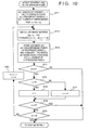
- FIG. 10 is a flowchart showing an processing sequence for determining a straight line for searching corresponding points.
- a preference order, n is set to 1, and a raster of a pixel of interest, r, is set to 1.
- the preference order, n shows relationship between objects overlaying in images.
- k1 is determined depending upon the input method, and when the cameras are arranged in parallel at equidistance from the object to pick up an image of an object, k1 is 1.
- the value, k2, is determined depending upon the distance between a camera and the object, and set to 20 (it is assumed that the viewpoint does not move more than 20 pixels) in this embodiment.
- nx represents the number of pixels of an image in the main scanning direction.
- m can be a real number, thus a value of x + m ⁇ (i - r) has to be rounded to the nearest whole number to determine the corresponding x coordinate.
- TH2 in the equation (6) is a threshold for finding the corresponding points, and set to 1200 in this embodiment.
- the reason why it is set to 1200 is that the epipolar plane is composed of four rasters, thus differences are calculated three times. It is assumed that, if the difference is about less than 20, colors are almost the same, the number 1200 is obtained from 3 ⁇ 20 ⁇ 20.
- the aforesaid method is described when a process is performed on each RBG pixel value, however, it can also be applied to a case where the value is converted into YIQ, HSI, or other color system, and the threshold can be set so as to suit the color systems.
- EPj(x + m ⁇ (i-r), i) does not exist (namely, x + m ⁇ (i-r) is outside of the range of the x axis (1 ⁇ nx))
- the process continues assuming that the point corresponding to m does not exist.
- EPj(x + m ⁇ (i-r), i) has already been processed at step S72, the process continues assuming that EPj(x + m ⁇ (i-r), i) - EPj(x,r) is 0.
- step S73 the corresponding points of the preference order n are determined from the straight line of slope m obtained at step S72, and stored.
- all of such points are stored as corresponding points to the preference order n, for convenience.
- the pixels which are determined as corresponding points are considered to have been processed. It should be noted that, if a corresponding point overlaps another corresponding point of the same preference order, the point having the larger value of m (the one whose slope is gentler with respect to the epipolar lines) is preferred.
- step S73 when the corresponding points obtained from the straight line of slope m are processed (they are determined as corresponding points of higher preference order, and the corresponding points of a pixel currently interested is hidden behind the corresponding points of a higher preference order), the points are not considered as the corresponding points on the straight line of slope m. Then, number of unprocessed pixels, w, is set.
- N indicates the complexity of the phenomenon in which objects hide other objects (occlusion). More specifically, if the value of N is large, a large number of objects are overlapped, whereas if the value of N is small, a small number of objects are overlapped.
- the number of N is set depending upon how in detail occlusion is expressed. Here, N is set to (R - 1) ⁇ 10, namely 30, as an empiric value.
- j-EPI j-th epipolar plane
- step S64 in Fig. 7 it is determined whether or not all rasters of input images are processed. If there is any unprocessed raster, the process moves to step S65 where value of j is incremented by 1, then the process goes back to step S62. Whereas, if it is determined that all rasters are processed, the corresponding point searching process is completed, and the process goes back to the flowchart in Fig. 6. Note, ny at step S64 is the total number of rasters of the input images.
- step S52 in Fig. 6 namely an image interpolation process
- the image interpolation process is performed by using the corresponding points obtained at step S51.
- the processing sequence is described with reference to Figs. 11 to 14.
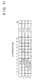
- Fig. 11 shows a j-th epipolar plane from which the aforesaid corresponding points are determined.
- a1 and c1 represent corresponding points of the preference order 1
- b2 represents corresponding points of the preference order 2.
- p images are interpolated between the input images at an equal interval will be described below. Note that, in this embodiment, p is chosen to be 2 in order to simplify the explanation.
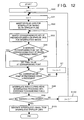
- Fig. 12 is a flowchart showing an processing sequence of the image interpolation process.
- a number of epipolar plane to be processed, j is set to 1.
- the preference order, n is set to 1.
- epipolar lines for interpolation images are inserted in the j-th epipolar plane.
- Fig. 13 shows an epipolar plane when two images are generated by interpolation between original images. Two epipolar lines are inserted between neighboring two epipolar lines on the j-th epipolar plane shown in Fig. 11.
- step S93 the corresponding points on the epipolar plane of the interpolation images are searched.
- pixels on the straight line connecting the corresponding points on the epipolar plane of the input images are extracted as corresponding points.
- step S94 whether or not a pixel assured as the corresponding point has been set as a corresponding point of the higher preference order is determined. If the pixel has not been set as the corresponding point of the higher preference order, the process proceeds to step S95, then a pixel value is set at the pixel as the corresponding point.
- the pixel value to be set at the corresponding point is an average of pixel values of corresponding points of the input images.
- the order of straight lines, obtained by connecting the corresponding points of the input images, to be used is the increasing order of the slope m when the preference order is same. Then, if the corresponding points indicate the same pixel, the value of the pixel is updated. Thereby, the corresponding points in a line having larger slope, m, is preferred. This is because the movement of the point on the images caused by the displacement of the viewpoint is greater when the object represented by the corresponding point is closer to the cameras (namely, the value of m is greater). Therefore, the points on the line having the larger value of m is preferred among a plurality of corresponding points of the same preference order, and thus occlusion can be dealt with.
- values of pixels on the interpolated epipolar line and on the straight line which connects the corresponding points, as described above, are set to the average of values of pixels on the straight line connecting corresponding points on the originals.
- the pixel values of points a and c on the straight line connecting the corresponding points are the average value of pixels represented by a1 and c1, respectively.
- a is set first, however, it is overwritten by the corresponding point c on the line having larger slope of m later.
- n is incremented by 1, and corresponding points having the preference order 2 start to be processed (steps S96 to S97).
- the processes to be applied to the corresponding points of the preference order 2 are the same as those performed at aforesaid steps S93 to S97. However, there are some pixels which have already interpolated when the corresponding points of the preference order 1 are processed, thus those interpolated pixels are not processed at step S94.
- a pixel (5, 8) is at the position which is to be interpolated with regard to corresponding points b2, however, it is already interpolated when the corresponding points c1 of the preference order 1 is processed, thus the pixel (5, 8) is not processed. Further, since the corresponding points b2 do not exist on the first raster of the epipolar plane of the original (see Fig. 11), neither does it exist at the corresponding points b2 on the first to third epipolar lines in Fig. 13. Furthermore, in the example of Fig. 13, occlusion occur at the points (4, 9) and (5, 8), and it is dealt with by the process described above.
- step S96 the process proceeds from step S96 to step S98 where pixels which are not interpolated during the above-said processes are interpolated with reference to neighboring pixels.
- interpolation there are methods of using an average value of neighboring pixels and of using a value of the pixel closest to the pixel to be interpolated.
- an image considering parallax in the vertical direction can be generated in such a manner that multi-viewpoint images picked up from image-taking viewpoints arranged at intersections of large meshes on a plane are stored and images are interpolated between the multi-viewpoint images in the right and left direction, then in the vertical direction.
- interpolation images in the vertical direction can be generated by extracting a straight line formed by pixels arranged in the vertical direction and constructing an epipolar plane.
- the input images can be picked up by a single camera by sliding its position so as to obtain equivalent images picked up by a plurality of cameras set at fixed positions.
- the direction of sliding of the camera and the x direction (main scanning direction) of the image sensing surface of the camera has to be parallel, or corresponding points will not form a straight line on an epipolar plane.
- the calibration described in the above embodiment can be applied to this case, too. Thus, it is apparent that it is possible to arrange corresponding points on a straight line.
- one of the cameras is defined as the reference camera, and the reference projection plane is defined by the image sensing surface of the reference camera, however, the present invention is not limited to this.
- An arbitrary plane can be defined as the reference projection plane. In such a case, by obtaining the reference parameters by finding relationship between the world coordinate system and the coordinate system of the arbitrary plane, calibration can be performed in the same manner as in the aforesaid embodiment. Note, since the equation of the reference projection plane in the world coordinate system is known, the relationship should be easily obtained.
- a rectangular area is extracted from the reference projection plane before the image interpolation processes, and the method for extracting the rectangular area is not limited to this.
- it can be extracted by obtaining pixel values of one line necessary to generate an epipolar plane and projecting on the reference projection plane.
- the j-th epipolar plane is constructed by extracting j-th rasters of images projected on the reference projection plane. Instead, pixel values of coordinate points corresponding to only j-th rasters projected on the reference plane can be obtained, then constructing the j-th epipolar plane. For example, if y component of each pixel on the j-th raster is yj, then the j-th epipolar plane can be formed by using values of pixels expressed by (xm', yj).
- the input images on image sensing surfaces can be corrected to images on a single plane, thus search of corresponding points at the image interpolation process can be performed by finding a straight line on an epipolar plane. Accordingly, it becomes easier to search corresponding points, thereby to generate interpolation images.
- Embodiments of the present invention may be constituted by a plurality of devices, or to an apparatus comprising a single device. Furthermore, embodiments may be attained by supplying a program to a system or apparatus.
- images picked up by a plurality of cameras can be corrected and projected on a single plane.
- an epipolar plane is formed from a plurality of images corrected to be images on the single plane, thereby corresponding points can be detected as a straight line. Accordingly, it becomes very easy to detect the corresponding points.
- new lines are generated by interpolation in an epipolar plane on the basis of the arrangement of the corresponding points detected on the epipolar plane, and a new image is generated by using the generated lines. Accordingly, it is possible to generate images seen from different viewpoints from those of the input images.
- occurrence of occlusion is detected from the arrangement of the detected corresponding points on an epipolar plane, thus more accurate interpolation images can be generated.
Landscapes
- Engineering & Computer Science (AREA)
- Physics & Mathematics (AREA)
- General Physics & Mathematics (AREA)
- Theoretical Computer Science (AREA)
- Multimedia (AREA)
- Quality & Reliability (AREA)
- Vascular Medicine (AREA)
- General Health & Medical Sciences (AREA)
- Health & Medical Sciences (AREA)
- Computer Graphics (AREA)
- Geometry (AREA)
- Software Systems (AREA)
- Computer Vision & Pattern Recognition (AREA)
- Image Processing (AREA)
- Length Measuring Devices By Optical Means (AREA)
- Image Analysis (AREA)
Claims (22)
- Appareil (3, 4, 5, 6) de traitement d'images destiné à traiter des données d'image d'entrée représentant des images d'un objet enregistré à une pluralité de points d'observation différents sur des surfaces de saisie d'image d'appareil de prise de vues dans des plans différents, pour produire des données d'image de sortie pour une image de l'objet à un point d'observation voulu, comprenant :un moyen (3) de calcul destiné à calculer des paramètres de conversion représentant la relation entre des positions de pixel sur la pluralité de surfaces de saisie d'image d'appareil de prise de vues et un plan de référence, ledit moyen (3) de calcul pouvant être mis en oeuvre pour calculer les paramètres de conversion pour chaque surface respective de saisie d'image d'appareil de prise de vues, sur la base d'un paramètre d'appareil de prise de vues représentant la correspondance entre un système de coordonnées de l'objet et le système de coordonnées de la surface de saisie d'image d'appareil de prise de vues, calculé en fonction d'une image prise de l'objet, et d'un paramètre de référence représentant la correspondance entre le système de coordonnées de l'objet et le système de coordonnées du plan de référence ;un moyen (4) de projection destiné à projeter la pluralité d'images d'entrée sur le plan de référence en se basant sur les paramètres de conversion calculés pour former des données d'images projetées ;un moyen (6) d'extraction destiné à extraire des données à partir des données d'images projetées représentant une pluralité d'images partielles ; etun moyen (5, 6) de formation de données d'image destiné à former des données d'image de sortie pour une image provenant d'un point d'observation voulu en utilisant les données extraites.
- Appareil selon la revendication 1, dans lequel le plan de référence est un plan représenté par le système de coordonnées de l'objet.
- Appareil selon la revendication 1, dans lequel le plan de référence est un plan incluant l'une des surfaces de saisie d'image d'appareil de prise de vues, et dans lequel le moyen (3) de calcul peut être mis en oeuvre pour calculer le paramètre de référence à partir du paramètre d'appareil de prise de vues pour la surface de saisie d'image d'appareil de prise de vues qui se trouve dans le plan du plan de référence.
- Appareil selon l'une quelconque des revendications précédentes, dans lequel les images partielles extraites du plan de référence par ledit moyen (6) d'extraction comprennent une image d'une zone dont le centre est l'intersection de la perpendiculaire issue du centre d'un objectif d'appareil de prise de vues sur le plan de référence.
- Appareil selon l'une quelconque des revendications précédentes, dans lequel les images partielles extraites par ledit moyen (6) d'extraction comprennent des plans épipolaires.
- Appareil selon la revendication 5, dans lequel ledit moyen (5, 6) de formation de données d'image comprendun moyen de formation de plan épipolaire destiné à former un plan épipolaire en se basant sur des lignes épipolaires extraites par ledit moyen (6) d'extraction ;un moyen de détermination destiné à déterminer des lignes droites formées par des points correspondants respectifs sur le plan épipolaire ; etun moyen générateur de ligne épipolaire destiné à engendrer une ligne épipolaire interpolée propre à être insérée entre une paire de lignes épipolaires du plan épipolaire en localisant des points dans la ligne épipolaire propre à être insérée, sur la base des lignes droites déterminées par ledit moyen de détermination ; etdans lequel le moyen (5, 6) de formation de données d'image peut être mis en oeuvre pour engendrer des données d'image de sortie pour l'image issue du point d'observation voulu en utilisant les lignes épipolaires insérées, engendrées par ledit moyen générateur de lignes épipolaires.
- Appareil selon la revendication 6, dans lequel ledit moyen de détermination peut être mis en oeuvre pour donner une priorité plus élevée à une ligne droite qui n'est pas interrompue par une autre ligne droite et pour donner une priorité plus basse à une ligne droite qui est interrompue par une autre ligne droite, et dans lequel ledit moyen générateur de ligne épipolaire peut être mis en oeuvre pour déterminer des valeurs de pixel de la ligne épipolaire insérée, en utilisant les lignes droites dans l'ordre de priorité descendant.
- Appareil selon la revendication 6 ou la revendication 7, dans lequel ledit moyen de détermination est agencé de façon telle que, lorsque l'on détermine une pluralité de lignes droites se coupant, on donne la priorité la plus élevée à la ligne droite dont la pente est la plus proche d'une ligne horizontale.
- Appareil selon l'une quelconque des revendications précédentes, comprenant en outre au moins un appareil de prise de vues (1a à 1d) destiné à engendrer les données d'image d'entrée.
- Appareil selon l'une quelconque des revendications précédentes, comprenant en outre un moyen (7) d'affichage destiné à afficher une image en utilisant les données d'image de sortie formées par le moyen (5, 6) de formation de données d'image.
- Procédé de traitement de données d'image d'entrée représentant des images d'un objet enregistré à une pluralité de points d'observation différents sur des surfaces de saisie d'image d'appareil de prise de vues dans des plans différents, pour produire des données d'image de sortie pour une image de l'objet à un point d'observation voulu, comprenant :le calcul de paramètres de conversion représentant la relation entre des positions de pixel sur la pluralité de surfaces de saisie d'image d'appareil de prise de vues et un plan de référence, les paramètres de conversion pour chaque surface respective de saisie d'image d'appareil de prise de vues étant calculés sur la base d'un paramètre d'appareil de prise de vues représentant la correspondance entre un système de coordonnées de l'objet et le système de coordonnées de la surface de saisie d'image d'appareil de prise de vues, calculé en fonction d'une image prise de l'objet et d'un paramètre de référence représentant la correspondance entre le système de coordonnées de l'objet et le système de coordonnées du plan de référence ;la projection de la pluralité d'images d'entrée sur le plan de référence en se basant sur les paramètres de conversion calculés pour former des données d'images projetées ;l'extraction de données à partir des données d'images projetées représentant une pluralité d'images partielles etla formation de données d'image de sortie pour une image provenant d'un point d'observation voulu en utilisant les données extraites.
- Procédé selon la revendication 11, dans lequel le plan de référence est un plan représenté par le système de coordonnées de l'objet.
- Procédé selon la revendication 11, dans lequel le plan de référence est un plan incluant l'une des surfaces de saisie d'image, et dans lequel, dans l'étape de calcul des paramètres de conversion, on calcule le paramètre de référence à partir du paramètre d'appareil de prise de vues pour la surface de saisie d'image qui se trouve dans le plan du plan de référence.
- Procédé selon l'une quelconque des revendications 11 à 13, dans lequel les images partielles extraites du plan de référence dans ladite étape d'extraction comprennent une image d'une zone dont le centre est l'intersection de la perpendiculaire issue du centre d'un objectif d'appareil de prise de vues sur le plan de référence.
- Procédé selon l'une quelconque des revendications 11 à 14, dans lequel les images partielles extraites dans ladite étape d'extraction comprennent des plans épipolaires.
- Procédé selon la revendication 15, dans lequel ladite étape de formation de données d'image comprend :une étape de formation de plan épipolaire formant un plan épipolaire basé sur des lignes épipolaires extraites dans ladite étape d'extraction ;une étape de détermination consistant à déterminer des lignes droites formées par des points correspondants respectifs sur le plan épipolaire ; etune étape de production de ligne épipolaire consistant à engendrer une ligne épipolaire interpolée à insérer entre une paire des lignes épipolaires du plan épipolaire en localisant des points dans la ligne épipolaire à insérer sur la base des lignes droites déterminées dans ladite étape de détermination ; etdans lequel, dans l'étape de formation de données d'image, les données d'image de sortie pour l'image issue du point d'observation voulu sont formées en utilisant les lignes épipolaires insérées engendrées dans ladite étape de production de ligne épipolaire.
- Procédé selon la revendication 16, dans lequel, dans ladite étape de détermination, on donne une priorité plus élevée à une ligne droite qui n'est pas interrompue par une autre ligne droite et pour donner une priorité plus basse à une ligne droite qui est interrompue par une autre; ligne droite et, dans ladite étape de production de ligne épipolaire, on détermine des valeurs de pixel de la ligne épipolaire insérée, en utilisant les lignes droites dans l'ordre de priorité descendant.
- Procédé selon la revendication 16 ou la revendication 17, dans lequel, dans ladite étape de détermination, lorsque l'on détermine une pluralité de lignes droites se coupant, on donne la priorité la plus élevée à la ligne droite dont la pente est la plus proche d'une ligne horizontale.
- Procédé selon l'une quelconque des revendications 11 à 18, comprenant en outre l'étape consistant à engendrer les données d'image d'entrée en utilisant une pluralité d'appareils de prise de vues.
- Procédé selon l'une quelconque des revendications 11 à 18, comprenant en outre l'étape consistant à engendrer les données d'image d'entrée en utilisant un unique appareil de prise de vues et en déplaçant l'appareil de prise de vues entre les imagés.
- Procédé selon l'une quelconque des revendications 11 à 20, comprenant en outre l'étape consistant à engendrer une image en utilisant les données d'image de sortie formées dans l'étape de formation de données d'image.
- Produit programme d'ordinateur comprenant des instructions destinées à faire qu'un appareil de traitement programmable devienne opérationnel pour mettre en oeuvre un procédé tel que présenté dans au moins l'une des revendications 11 à 21.
Applications Claiming Priority (3)
| Application Number | Priority Date | Filing Date | Title |
|---|---|---|---|
| JP8649594 | 1994-04-25 | ||
| JP86495/94 | 1994-04-25 | ||
| JP6086495A JPH07294215A (ja) | 1994-04-25 | 1994-04-25 | 画像処理方法及び装置 |
Publications (3)
| Publication Number | Publication Date |
|---|---|
| EP0680014A2 EP0680014A2 (fr) | 1995-11-02 |
| EP0680014A3 EP0680014A3 (fr) | 1996-12-04 |
| EP0680014B1 true EP0680014B1 (fr) | 2001-07-18 |
Family
ID=13888567
Family Applications (1)
| Application Number | Title | Priority Date | Filing Date |
|---|---|---|---|
| EP95302728A Expired - Lifetime EP0680014B1 (fr) | 1994-04-25 | 1995-04-24 | Procédé et appareil de traitement d'images |
Country Status (4)
| Country | Link |
|---|---|
| US (1) | US5937105A (fr) |
| EP (1) | EP0680014B1 (fr) |
| JP (1) | JPH07294215A (fr) |
| DE (1) | DE69521739T2 (fr) |
Cited By (2)
| Publication number | Priority date | Publication date | Assignee | Title |
|---|---|---|---|---|
| US20210390670A1 (en) * | 2020-06-16 | 2021-12-16 | Samsung Electronics Co., Ltd. | Image processing system for performing image quality tuning and method of performing image quality tuning |
| US20210390671A1 (en) * | 2020-06-16 | 2021-12-16 | Samsung Electronics Co., Ltd. | Image processing system for performing image quality tuning and method of performing image quality tuning |
Families Citing this family (29)
| Publication number | Priority date | Publication date | Assignee | Title |
|---|---|---|---|---|
| US5475422A (en) * | 1993-06-21 | 1995-12-12 | Nippon Telegraph And Telephone Corporation | Method and apparatus for reconstructing three-dimensional objects |
| JPH10232626A (ja) * | 1997-02-20 | 1998-09-02 | Canon Inc | 立体画像表示装置 |
| JP3715091B2 (ja) * | 1997-10-15 | 2005-11-09 | 三菱電機株式会社 | 画像処理装置 |
| GB9810553D0 (en) * | 1998-05-15 | 1998-07-15 | Tricorder Technology Plc | Method and apparatus for 3D representation |
| US6198852B1 (en) * | 1998-06-01 | 2001-03-06 | Yeda Research And Development Co., Ltd. | View synthesis from plural images using a trifocal tensor data structure in a multi-view parallax geometry |
| GB2358308B (en) * | 1999-11-25 | 2004-03-24 | Canon Kk | Image processing apparatus |
| US6970591B1 (en) | 1999-11-25 | 2005-11-29 | Canon Kabushiki Kaisha | Image processing apparatus |
| JP2001274973A (ja) * | 2000-03-24 | 2001-10-05 | Sanyo Electric Co Ltd | 顕微鏡画像合成装置、顕微鏡画像合成方法、顕微鏡画像合成処理プログラムを記録したコンピュータ読み取り可能な記録媒体 |
| GB2380887A (en) * | 2001-10-13 | 2003-04-16 | Isis Innovation | Lens distortion correction using correspondence points within images which are constrained to lie on the same epipolar curve |
| JP2003141527A (ja) * | 2001-11-07 | 2003-05-16 | Japan Science & Technology Corp | 多視点画像処理システムのキャリブレーション装置及びキャリブレーション方法 |
| US7716207B2 (en) * | 2002-02-26 | 2010-05-11 | Odom Paul S | Search engine methods and systems for displaying relevant topics |
| JP4095491B2 (ja) * | 2003-05-19 | 2008-06-04 | 本田技研工業株式会社 | 距離測定装置、距離測定方法、及び距離測定プログラム |
| US7190496B2 (en) * | 2003-07-24 | 2007-03-13 | Zebra Imaging, Inc. | Enhanced environment visualization using holographic stereograms |
| DE102004034751B4 (de) * | 2004-07-17 | 2006-08-17 | Fraunhofer-Gesellschaft zur Förderung der angewandten Forschung e.V. | Verfahren und Vorrichtung zur Korrektur von Bildverzerrungen bei digitalen Bildaufnahmen |
| KR100603601B1 (ko) * | 2004-11-08 | 2006-07-24 | 한국전자통신연구원 | 다시점 콘텐츠 생성 장치 및 그 방법 |
| US8014588B2 (en) * | 2005-11-04 | 2011-09-06 | Cognitech, Inc. | System and method for three-dimensional estimation based on image data |
| JP4487952B2 (ja) * | 2006-02-27 | 2010-06-23 | ソニー株式会社 | カメラ装置及び監視システム |
| US20080144174A1 (en) * | 2006-03-15 | 2008-06-19 | Zebra Imaging, Inc. | Dynamic autostereoscopic displays |
| US20080170293A1 (en) * | 2006-03-15 | 2008-07-17 | Lucente Mark E | Dynamic autostereoscopic displays |
| US9843790B2 (en) | 2006-03-15 | 2017-12-12 | Fovi 3D, Inc. | Dynamic autostereoscopic displays |
| JP4382797B2 (ja) | 2006-11-09 | 2009-12-16 | 株式会社山武 | 対応点探索方法および3次元位置計測方法 |
| JP4993686B2 (ja) * | 2006-11-09 | 2012-08-08 | アズビル株式会社 | 対応点探索方法および3次元位置計測方法 |
| JP4858346B2 (ja) * | 2007-07-26 | 2012-01-18 | 株式会社島津製作所 | マーカー像識別装置及びマーカー像識別方法 |
| US8422825B1 (en) * | 2008-11-05 | 2013-04-16 | Hover Inc. | Method and system for geometry extraction, 3D visualization and analysis using arbitrary oblique imagery |
| JP4852591B2 (ja) | 2008-11-27 | 2012-01-11 | 富士フイルム株式会社 | 立体画像処理装置、方法及び記録媒体並びに立体撮像装置 |
| US10008027B1 (en) | 2014-10-20 | 2018-06-26 | Henry Harlyn Baker | Techniques for determining a three-dimensional representation of a surface of an object from a set of images |
| US10430994B1 (en) | 2016-11-07 | 2019-10-01 | Henry Harlyn Baker | Techniques for determining a three-dimensional textured representation of a surface of an object from a set of images with varying formats |
| DE102017116495B4 (de) * | 2017-07-21 | 2019-10-10 | Carl Zeiss Smt Gmbh | Verfahren zur Verzeichnungskorrektur einer ersten Abbildungsoptik eines ersten Messsystems |
| US11790610B2 (en) | 2019-11-11 | 2023-10-17 | Hover Inc. | Systems and methods for selective image compositing |
Family Cites Families (5)
| Publication number | Priority date | Publication date | Assignee | Title |
|---|---|---|---|---|
| US5193124A (en) * | 1989-06-29 | 1993-03-09 | The Research Foundation Of State University Of New York | Computational methods and electronic camera apparatus for determining distance of objects, rapid autofocusing, and obtaining improved focus images |
| GB9011922D0 (en) * | 1990-05-29 | 1990-07-18 | Europ Vision Syst Centre | Machine vision stereo matching |
| JP2941412B2 (ja) * | 1990-11-26 | 1999-08-25 | 株式会社東芝 | 3次元計測方法 |
| US5528194A (en) * | 1991-05-13 | 1996-06-18 | Sony Corporation | Apparatus and method for performing geometric transformations on an input image |
| US5577130A (en) * | 1991-08-05 | 1996-11-19 | Philips Electronics North America | Method and apparatus for determining the distance between an image and an object |
-
1994
- 1994-04-25 JP JP6086495A patent/JPH07294215A/ja not_active Withdrawn
-
1995
- 1995-04-24 DE DE69521739T patent/DE69521739T2/de not_active Expired - Lifetime
- 1995-04-24 EP EP95302728A patent/EP0680014B1/fr not_active Expired - Lifetime
-
1998
- 1998-01-20 US US09/009,187 patent/US5937105A/en not_active Expired - Lifetime
Cited By (3)
| Publication number | Priority date | Publication date | Assignee | Title |
|---|---|---|---|---|
| US20210390670A1 (en) * | 2020-06-16 | 2021-12-16 | Samsung Electronics Co., Ltd. | Image processing system for performing image quality tuning and method of performing image quality tuning |
| US20210390671A1 (en) * | 2020-06-16 | 2021-12-16 | Samsung Electronics Co., Ltd. | Image processing system for performing image quality tuning and method of performing image quality tuning |
| US11900570B2 (en) * | 2020-06-16 | 2024-02-13 | Samsung Electronics Co., Ltd. | Image processing system for performing image quality tuning and method of performing image quality tuning |
Also Published As
| Publication number | Publication date |
|---|---|
| DE69521739T2 (de) | 2002-05-23 |
| EP0680014A3 (fr) | 1996-12-04 |
| US5937105A (en) | 1999-08-10 |
| JPH07294215A (ja) | 1995-11-10 |
| DE69521739D1 (de) | 2001-08-23 |
| EP0680014A2 (fr) | 1995-11-02 |
Similar Documents
| Publication | Publication Date | Title |
|---|---|---|
| EP0680014B1 (fr) | Procédé et appareil de traitement d'images | |
| EP0680019B1 (fr) | Méthode et appareil de traitement d'images | |
| US6191808B1 (en) | Image processing method with viewpoint compensation and apparatus therefor | |
| CA3017827C (fr) | Generation de vue tramee efficace a partir de vues intermediaires | |
| US6263100B1 (en) | Image processing method and apparatus for generating an image from the viewpoint of an observer on the basis of images obtained from a plurality of viewpoints | |
| US6608622B1 (en) | Multi-viewpoint image processing method and apparatus | |
| JP4065488B2 (ja) | 3次元画像生成装置、3次元画像生成方法及び記憶媒体 | |
| KR20160121798A (ko) | 직접적인 기하학적 모델링이 행해지는 hmd 보정 | |
| CN211128024U (zh) | 3d显示设备 | |
| US9420263B2 (en) | Information processor and information processing method | |
| KR100668073B1 (ko) | 다시점 영상의 왜곡 보정처리 방법 | |
| JP3032414B2 (ja) | 画像処理方法および画像処理装置 | |
| CN108450031A (zh) | 图像捕获装置 | |
| JP3054312B2 (ja) | 画像処理装置及び方法 | |
| JPH08201941A (ja) | 3次元画像形成方法 | |
| JPH0749944A (ja) | 画像処理方法およびその装置 | |
| JPH08116556A (ja) | 画像処理方法および装置 | |
| JP2795784B2 (ja) | 複数視点3次元画像入力装置 | |
| EP3229470B1 (fr) | Génération de vue de toile efficace à partir des vues intermédiaires | |
| JPH07274063A (ja) | 画像処理方法及びその装置 | |
| JPH07296194A (ja) | 画像処理方法およびその装置 | |
| JPH07296139A (ja) | 画像処理方法及びその装置 | |
| JPH09261537A (ja) | 画像処理装置及び画像処理方法 | |
| JPH08180206A (ja) | 画像の立体表示方法 | |
| JPH08279961A (ja) | 画像処理方法及びその装置 |
Legal Events
| Date | Code | Title | Description |
|---|---|---|---|
| PUAI | Public reference made under article 153(3) epc to a published international application that has entered the european phase |
Free format text: ORIGINAL CODE: 0009012 |
|
| AK | Designated contracting states |
Kind code of ref document: A2 Designated state(s): DE FR GB IT NL |
|
| PUAL | Search report despatched |
Free format text: ORIGINAL CODE: 0009013 |
|
| RHK1 | Main classification (correction) |
Ipc: G06T 15/10 |
|
| AK | Designated contracting states |
Kind code of ref document: A3 Designated state(s): DE FR GB IT NL |
|
| 17P | Request for examination filed |
Effective date: 19970416 |
|
| 17Q | First examination report despatched |
Effective date: 19970626 |
|
| GRAG | Despatch of communication of intention to grant |
Free format text: ORIGINAL CODE: EPIDOS AGRA |
|
| GRAG | Despatch of communication of intention to grant |
Free format text: ORIGINAL CODE: EPIDOS AGRA |
|
| GRAG | Despatch of communication of intention to grant |
Free format text: ORIGINAL CODE: EPIDOS AGRA |
|
| GRAH | Despatch of communication of intention to grant a patent |
Free format text: ORIGINAL CODE: EPIDOS IGRA |
|
| GRAH | Despatch of communication of intention to grant a patent |
Free format text: ORIGINAL CODE: EPIDOS IGRA |
|
| GRAH | Despatch of communication of intention to grant a patent |
Free format text: ORIGINAL CODE: EPIDOS IGRA |
|
| GRAH | Despatch of communication of intention to grant a patent |
Free format text: ORIGINAL CODE: EPIDOS IGRA |
|
| GRAA | (expected) grant |
Free format text: ORIGINAL CODE: 0009210 |
|
| AK | Designated contracting states |
Kind code of ref document: B1 Designated state(s): DE FR GB IT NL |
|
| PG25 | Lapsed in a contracting state [announced via postgrant information from national office to epo] |
Ref country code: NL Free format text: LAPSE BECAUSE OF FAILURE TO SUBMIT A TRANSLATION OF THE DESCRIPTION OR TO PAY THE FEE WITHIN THE PRESCRIBED TIME-LIMIT Effective date: 20010718 Ref country code: IT Free format text: LAPSE BECAUSE OF FAILURE TO SUBMIT A TRANSLATION OF THE DESCRIPTION OR TO PAY THE FEE WITHIN THE PRE;WARNING: LAPSES OF ITALIAN PATENTS WITH EFFECTIVE DATE BEFORE 2007 MAY HAVE OCCURRED AT ANY TIME BEFORE 2007. THE CORRECT EFFECTIVE DATE MAY BE DIFFERENT FROM THE ONE RECORDED.SCRIBED TIME-LIMIT Effective date: 20010718 |
|
| REF | Corresponds to: |
Ref document number: 69521739 Country of ref document: DE Date of ref document: 20010823 |
|
| ET | Fr: translation filed | ||
| REG | Reference to a national code |
Ref country code: GB Ref legal event code: IF02 |
|
| NLV1 | Nl: lapsed or annulled due to failure to fulfill the requirements of art. 29p and 29m of the patents act | ||
| PLBE | No opposition filed within time limit |
Free format text: ORIGINAL CODE: 0009261 |
|
| STAA | Information on the status of an ep patent application or granted ep patent |
Free format text: STATUS: NO OPPOSITION FILED WITHIN TIME LIMIT |
|
| 26N | No opposition filed | ||
| PGFP | Annual fee paid to national office [announced via postgrant information from national office to epo] |
Ref country code: DE Payment date: 20130430 Year of fee payment: 19 Ref country code: GB Payment date: 20130418 Year of fee payment: 19 |
|
| PGFP | Annual fee paid to national office [announced via postgrant information from national office to epo] |
Ref country code: FR Payment date: 20130517 Year of fee payment: 19 |
|
| REG | Reference to a national code |
Ref country code: DE Ref legal event code: R119 Ref document number: 69521739 Country of ref document: DE |
|
| GBPC | Gb: european patent ceased through non-payment of renewal fee |
Effective date: 20140424 |
|
| REG | Reference to a national code |
Ref country code: FR Ref legal event code: ST Effective date: 20141231 |
|
| REG | Reference to a national code |
Ref country code: DE Ref legal event code: R119 Ref document number: 69521739 Country of ref document: DE Effective date: 20141101 |
|
| PG25 | Lapsed in a contracting state [announced via postgrant information from national office to epo] |
Ref country code: GB Free format text: LAPSE BECAUSE OF NON-PAYMENT OF DUE FEES Effective date: 20140424 Ref country code: DE Free format text: LAPSE BECAUSE OF NON-PAYMENT OF DUE FEES Effective date: 20141101 |
|
| PG25 | Lapsed in a contracting state [announced via postgrant information from national office to epo] |
Ref country code: FR Free format text: LAPSE BECAUSE OF NON-PAYMENT OF DUE FEES Effective date: 20140430 |