EP0677768A1 - Dispositif d'affichage à cristal liquide caractérisée par une lisibilité améliorée - Google Patents
Dispositif d'affichage à cristal liquide caractérisée par une lisibilité améliorée Download PDFInfo
- Publication number
- EP0677768A1 EP0677768A1 EP95105451A EP95105451A EP0677768A1 EP 0677768 A1 EP0677768 A1 EP 0677768A1 EP 95105451 A EP95105451 A EP 95105451A EP 95105451 A EP95105451 A EP 95105451A EP 0677768 A1 EP0677768 A1 EP 0677768A1
- Authority
- EP
- European Patent Office
- Prior art keywords
- display
- liquid crystal
- crystal layer
- diffuser
- facets
- Prior art date
- Legal status (The legal status is an assumption and is not a legal conclusion. Google has not performed a legal analysis and makes no representation as to the accuracy of the status listed.)
- Granted
Links
Images


Classifications
-
- G—PHYSICS
- G02—OPTICS
- G02F—OPTICAL DEVICES OR ARRANGEMENTS FOR THE CONTROL OF LIGHT BY MODIFICATION OF THE OPTICAL PROPERTIES OF THE MEDIA OF THE ELEMENTS INVOLVED THEREIN; NON-LINEAR OPTICS; FREQUENCY-CHANGING OF LIGHT; OPTICAL LOGIC ELEMENTS; OPTICAL ANALOGUE/DIGITAL CONVERTERS
- G02F1/00—Devices or arrangements for the control of the intensity, colour, phase, polarisation or direction of light arriving from an independent light source, e.g. switching, gating or modulating; Non-linear optics
- G02F1/01—Devices or arrangements for the control of the intensity, colour, phase, polarisation or direction of light arriving from an independent light source, e.g. switching, gating or modulating; Non-linear optics for the control of the intensity, phase, polarisation or colour
- G02F1/13—Devices or arrangements for the control of the intensity, colour, phase, polarisation or direction of light arriving from an independent light source, e.g. switching, gating or modulating; Non-linear optics for the control of the intensity, phase, polarisation or colour based on liquid crystals, e.g. single liquid crystal display cells
- G02F1/133—Constructional arrangements; Operation of liquid crystal cells; Circuit arrangements
- G02F1/1333—Constructional arrangements; Manufacturing methods
- G02F1/1335—Structural association of cells with optical devices, e.g. polarisers or reflectors
- G02F1/1336—Illuminating devices
- G02F1/133615—Edge-illuminating devices, i.e. illuminating from the side
-
- G—PHYSICS
- G02—OPTICS
- G02F—OPTICAL DEVICES OR ARRANGEMENTS FOR THE CONTROL OF LIGHT BY MODIFICATION OF THE OPTICAL PROPERTIES OF THE MEDIA OF THE ELEMENTS INVOLVED THEREIN; NON-LINEAR OPTICS; FREQUENCY-CHANGING OF LIGHT; OPTICAL LOGIC ELEMENTS; OPTICAL ANALOGUE/DIGITAL CONVERTERS
- G02F1/00—Devices or arrangements for the control of the intensity, colour, phase, polarisation or direction of light arriving from an independent light source, e.g. switching, gating or modulating; Non-linear optics
- G02F1/01—Devices or arrangements for the control of the intensity, colour, phase, polarisation or direction of light arriving from an independent light source, e.g. switching, gating or modulating; Non-linear optics for the control of the intensity, phase, polarisation or colour
- G02F1/13—Devices or arrangements for the control of the intensity, colour, phase, polarisation or direction of light arriving from an independent light source, e.g. switching, gating or modulating; Non-linear optics for the control of the intensity, phase, polarisation or colour based on liquid crystals, e.g. single liquid crystal display cells
- G02F1/133—Constructional arrangements; Operation of liquid crystal cells; Circuit arrangements
- G02F1/1333—Constructional arrangements; Manufacturing methods
- G02F1/1335—Structural association of cells with optical devices, e.g. polarisers or reflectors
- G02F1/133504—Diffusing, scattering, diffracting elements
Definitions
- This invention relates to a liquid crystal display having an enlarged viewing zone. More particularly, this invention relates to a liquid crystal display which provides a substantially large and uniform viewing envelope with respect to contrast, ambient reflection, inversion (i.e. lack of), resolution, and color uniformity.
- LCDs Liquid crystal displays
- Such displays were widely used originally in, for example, watches, calculators, radios, and other products requiring character and/or image indicators in relatively small display areas.
- Attempts to employ larger area LCDs initially provided such unacceptable levels of contrast, cost, and other characteristics as to render them commercially infeasible.
- AMLCD active
- PMLCD passive matrix type displays
- AMLCDs for example, have achieved widespread acceptance in portable computers, laptop computers, word processors, and avionic cockpit applications.
- Other products in which such displays are useful include flat screen and projection television systems.
- these characteristics are most needed, they have not always been capable of optimization. Indeed, one characteristic heretofore may have had to have been traded off against another in order to achieve commercial acceptability.
- Liquid crystal materials are useful for such displays because light traveling therethrough is affected by the anisotropic or birefringent value ( ⁇ n) of the LC material, which in turn can be controlled by the application of a variable voltage across the LC.
- Backlit liquid crystal displays are desirable because the transmission of light emanating from the backlight assembly can be controlled with a substantially low amount of power, i.e. less than that typically required to illuminate other types of prior art displays such as CRTs.
- the thin profile of such LCDs gives them an added advantage over conventional CRTs.
- AMLCDs The information displayed by, for example, AMLCDs is presented in the form of a matrix array of rows and columns of numerals or characters, which are generated by a number of segmented electrodes arranged in a matrix pattern.
- the segments are connected by individual leads to driving electronics, which act to apply a variable and controllable voltage to the appropriate combination of segments to thereby display the desired data and information by controlling the light transmitted through the LC material.
- Graphic information in, for example, avionic cockpit applications or television displays may be achieved by an active matrix of pixels which are connected by an X-Y sequential addressing scheme between two sets of perpendicular conductive lines (i.e. row and column address lines).
- amorphous silicon (a-Si) TFTs amorphous silicon thin film diodes
- MIMs amorphous silicon thin film diodes
- STNs are generally multiplexed in order to selectively address each pixel.
- the contrast ratio (i.e. contrast - 1) in a NW display is the difference between "off state” transmission versus "on state” transmission in low ambient conditions, and is determined by dividing the "off state” light transmission (high intensity white light) by the "on state” or darkened intensity. For example, if an "off state” (i.e. below the threshold driving voltage) NW display exhibits an intensity of 200 fL and the same display in its fully driven “on state” emits 5 fL at the same viewing angle that the aforesaid 200 fL measurement was taken, both in low ambient conditions, then the display's contrast ratio at that particular viewing angle is 40 or 40:1.
- the primary factor limiting the contrast ratio is the amount of light which leaks through the display in the darkened or "on state".
- the primary factor limiting the contrast ratio achievable is the amount of light which leaks through the display in the darkened or "off state”.
- the amount of ambient light reflected by a display panel is typically measured via conventional specular and diffused reflection tests discussed later herein and illustrated by Figures 23 and 24.
- Gray level performance of liquid crystal displays and the corresponding amount of inversion is also very important in determining the quality of an LCD.
- Conventional AMLCDs utilize anywhere from about 8 to 64 different driving voltages. These different driving voltages are typically referred to as gray level voltages.
- the intensity of light transmitted through the colored subpixel, pixel, or display depends upon its driving voltage. Accordingly, gray level voltages are used to generate different shades of different colors so as to create different colors when, for example, these shades are mixed with one another.
- the lower the driving voltage in such a normally white display the higher the intensity of light emitted therefrom.
- normally black twisted nematic displays the higher the driving voltage in normally black twisted nematic displays.
- a gray level V on is any voltage greater than V th (threshold voltage) up to about 5.0 to 6.5 volts.
- gray level performance of, for example, NW displays it is desirable to have an intensity versus driving voltage curve wherein the intensity (i.e. fL) of light emitted from the pixel or subpixel continually and monotonically decreases as the driving voltage increases.
- intensity i.e. fL
- NB displays the intensity versus driving voltage curve
- Inversion occurs in a NW display when the intensity (fL) at certain viewing angles at e.g. 3.0 volts is greater than that at 2.0 volts. This leads to different intensities and/or colors of light being viewed at various viewing angles of the display even when the same voltage is being applied. Accordingly, the elimination of inversion in LCDs is an always desired result.
- the problems of inversion are more thoroughly discussed in co-pending commonly owned Serial No. 08/167,652, filed December 15, 1993, the disclosure of which is incorporated herein by reference.
- normally black (NB) displays are much harder to manufacture than NW displays due to their high dependence on the cell gap or thickness "d" of the liquid crystal material. Accordingly, a long felt need in the art, particularly in the art of manufacturing larger LCDs, has been the ability to construct a normally white display with high contrast ratios over a large range of both vertical and horizontal viewing angles, rather than having to resort to the more difficult to manufacture NB display to achieve these characteristics. While the subject invention is equally applicable to both NW and NB displays, one of its unique features is that it so successfully solves this long felt need by achieving at least those characteristics of NB displays in the simpler to construct NW displays provided according to this invention.
- retardation films have been used in normally white displays in an attempt to enlarge their relatively small effective viewing areas and to reduce inversion. See, for example, U.S. Patent No. 5,184,236 and aforesaid Serial No. 08/167,652.
- These normally white TN displays with dual retardation films achieve fairly high contrast ratios over a relatively large range of viewing angles compared to other NW displays.
- the reflectance of ambient light e.g. sunlight
- an AR coating is provided exterior the front polarizer.
- liquid crystal display normally white, normally black, active, passive, TN, STN, etc.
- the display maintaining color uniformity over a wide range of viewing angles and having high resolution, relatively low ambient light reflectance, and little or no inversion.
- this invention fulfills the above-described needs in the art by providing in a backlit liquid crystal display which includes a backlight assembly for directing light toward a display panel, the display panel including a liquid crystal layer and being capable of providing an image to a remotely positioned viewer, the improvement comprising: an optical system disposed on the viewer side of the liquid crystal layer, the optical system including a film means for substantially enlarging the effective viewing zone of the liquid crystal display and for providing substantial uniformity of illumination thereto with respect to contrast ratio and color uniformity, and wherein said film means has a plurality of optical facets therein.
- This invention further fulfills the above-described needs in the art by providing a method of providing an image to a viewer from a liquid crystal display device, the method comprising the steps of:
- the optical system provided in the display has a contrast ratio of at least about 70:1 along the 0° vertical viewing axis at horizontal viewing angles up to about ⁇ 60°.
- the optical system further includes a holographic diffuser affixed to the display panel on the viewer side of the liquid crystal layer, wherein the display panel, when while substantially collimated light is directed toward the panel from the backlight, has at least the following viewing characteristics:
- a backlit LCD comprising: a backlight for directing light toward a display panel having a liquid crystal layer; electrode means for applying a voltage across the liquid crystal layer; and integral reverse-collimating and refracting means for substantially collimating ambient light directed toward the liquid crystal layer thereby reducing the amount of ambient light reflection off of the display panel, and for refracting light from the backlight after it exits the liquid crystal layer so as to maintain the resolution of the image displayed to the viewer over a wide range of viewing angles.
- a backlit LCD including a backlight for directing light toward a display panel, the display panel including a liquid crystal layer and means for applying a voltage across the liquid crystal layer, the display being capable of providing an image to a remotely positioned viewer, the improvement comprising: reverse-collimating means for substantially collimating ambient light directed toward the display panel so as to reduce ambient light reflection off of the display panel, the reverse-collimating means disposed on the viewer side of the liquid crystal layer.
- Figure 1(a) is a side elevational cross sectional view of a backlit liquid crystal display assembly according to a first embodiment of this invention, including a diffuser and optical film positioned exterior the front polarizer.
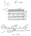
- Figure 1(b) is a side elevational cross-sectional view of a backlit LCD assembly according to a second embodiment of this invention.
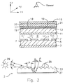
- Figure 2 is a side elevational cross sectional view of a backlit liquid crystal display assembly according to a third embodiment of this invention.
- Figure 3 is a side elevational cross sectional view of a backlit liquid crystal display assembly according to a fourth embodiment of this invention.
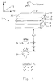
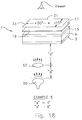
- Figure 4 is an exploded perspective view of the first backlit active matrix liquid crystal display of Example 1 including optical film 17.
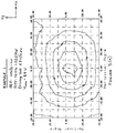
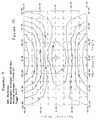
- Figure 5(a) is the contrast ratio curve graph or plot of the AMLCD of Example 1 including the diffuser and corresponding optical film. This and all other contrast ratio plots herein was measured using white light.
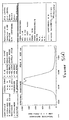
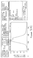
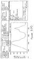
- Figures 5(b)-5(g) are color coordinate and light spectrum graphs of the Example 1 AMLCD including both the diffuser and optical film exterior the front polarizer.
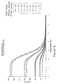
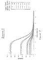
- Figure 6 is the intensity versus driving voltage plot or graph illustrating the intensity at various vertical viewing angles along the 0° horizontal axis of the Example 1 AMLCD having a diffuser and corresponding optical film.
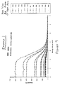
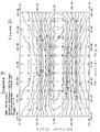
- Figure 7 is the intensity versus driving voltage plot illustrating the intensity at a variety of vertical viewing angles along the 0° horizontal axis of the second Example 1 AMLCD, this AMLCD utilizing only a diffuser, and no optical faceted film adjacent thereto.
- Figure 8 is the intensity versus driving voltage plot illustrating the intensity at a variety of horizontal viewing angles along the 0° vertical axis of the Example 1 AMLCD having both a diffuser and adjacent optical faceted film (see Figures 5(a) and 6).
- Figure 9 is the intensity versus driving voltage plot illustrating the intensity at a variety of horizontal viewing angles along the 0° vertical axis of the Example 1 AMLCD having no optical film disposed adjacent the diffuser (see Figure 7).
- Figure 10 is an exploded perspective view of the backlit AMLCD of Example 2.
- Figure 11 is the contrast ratio curve graph or plot of the backlit AMLCD of Example 2.
- Figure 12 is an exploded perspective view of the backlit AMLCD of Example 3.
- Figure 13 is the contrast ratio curve graph of the backlit AMLCD of Example 3.
- Figure 14 is an exploded perspective view of the backlit AMLCD of Example 4.
- Figure 15 is the contrast ratio curve graph of the backlit AMLCD of Example 4.
- Figure 16 is an exploded perspective view of the backlit AMLCD of Example 5.
- Figure 17 is the contrast ratio curve graph or plot of the backlit AMLCD of Example 5.
- Figure 18 is an exploded perspective view of the backlit AMLCD of Example 6.
- Figure 19 is the contrast ratio curve plot of the backlit AMLCD of Example 6.
- Figure 20 is an exploded perspective view of the backlit AMLCD of Example 7.
- Figure 21 is the contrast ratio curve plot of the backlit AMLCD of Example 7.
- Figure 22 is a graph illustrating the angular relationship between the horizontal and vertical viewing angles discussed herein, and their relationship with the conventional liquid crystal display viewing angles ⁇ and ⁇ .
- Figure 23 is a schematic diagram illustrating the meaning and definition of the term "specular reflection" as used herein, this definition also being the conventional meaning of the term.
- Figure 24 is a schematic diagram illustrating the meaning and definition of the term "diffused reflection" as used herein, this definition also being the conventional meaning of the term.
- liquid crystal displays discussed herein include liquid crystal material with a birefringence ( ⁇ n) of 0.084 at room temperature unless otherwise specified, this LC material being Model No. ZLI-4718 obtained from Merck.
- Figure 22 illustrates the angular relationships between the horizontal and vertical viewing axes and viewing angles described herein relative to a liquid crystal display panel and conventional LCD angles ⁇ and ⁇ .
- the +X, +Y, and +Z axes shown in Figure 22 are also defined in other figures herein.
- a lamp directs light toward display panel 1 from a predetermined horizontal angle relative to normal, i.e. 30° in this example.
- a photometer is positioned so as to receive reflected ambient light from the ambient source by way of display panel 1.
- the photometer is positioned at the same predetermined angle from normal, or 30° in this example, but on the opposite side of normal with respect to the ambient source.
- the photometer and ambient source are both along the 0° vertical axis.
- the ambient source and photometer are, of course, disposed in the same horizontal plane and are angularly offset from normal about opposite sides thereof at equivalent angles. For example, if the ambient source outputs 100 fL of light towards display panel 1 and the photometer of Figure 23 picks up 2 fL off of panel 1, then the specular 30° reflection of the display panel is 2%.
- Figure 24 illustrates what is meant herein by the term "diffused reflection" with respect to ambient light.
- An ambient light source e.g. the sun
- a photometer, horizontally co-planar with the ambient source is disposed at a predetermined horizontal angle relative to the ambient source, either 30° or 45° in this Figure 24 example.
- the amount or intensity of light picked up by the photometer at a predetermined angle dictates the diffused reflectivity of display panel 1 for that particular angle.
- the ambient light source in Figure 24 directs 100 fL towards display panel 1, and the photometer, offset 30° from the ambient source, picks up 4 fL off of display panel 1, then the display has a diffused 30° reflection or reflectance of 4%.
- the photometer is positioned 45° relative to the ambient source and picks up 2 fL, then the display panel has a diffused 45° reflection of 2%.
- Figures 23-24 define the terms "specular reflection” and “diffused reflection” as used herein unless otherwise specified. These are, of course, the conventional definitions of both specular and diffused reflection in the liquid crystal display art. See, for example, MIL-L-85762a.
- FIG. 1(a) there is illustrated a side elevational cross sectional view of a liquid crystal display assembly according to a first embodiment of this invention, including display panel 1, and backlighting assembly 2.
- Display panel 1 includes from the rear forward toward the viewer, rear or entrance linear polarizer 3, transparent substrate 5 preferably made of glass or plastic, individual pixel electrodes 7 defining a plurality of pixels or colored subpixels in panel 1, conventional liquid crystal layer 9 preferably but not necessarily of the twisted nematic type, common electrode 11, front transparent substrate 13 also preferably made of glass or plastic, conventional front linear polarizer 15, optical film 17 including a plurality of optical facets 19, diffuser 21, and finally optional glass sheet 35 including an anti-reflective (AR) coating on the exterior surface thereof.
- rear or entrance linear polarizer 3 transparent substrate 5 preferably made of glass or plastic
- individual pixel electrodes 7 defining a plurality of pixels or colored subpixels in panel 1
- conventional liquid crystal layer 9 preferably but not necessarily of the twisted nematic type
- common electrode 11 common electrode
- front transparent substrate 13 also preferably made of glass or plastic
- conventional front linear polarizer 15 optical film 17 including a plurality of optical facets 19, diffuser 21, and finally optional glass sheet 35 including an
- Backlight assembly 2 includes optical film 23 including a plurality of facets 25 defined in its surface facing display panel 1, and reflective layer 27 disposed on the flat or exterior surface of optical film 23.
- Layer 27 is preferably made of a reflective metal, such as aluminum, while optical film 23 is preferably "Right Angle Film” or "RAF” manufactured and commercially available from 3M, St. Paul, Minnesota.
- a backlight using "TRAF” optical film commercially available from 3M could also be utilized to provided substantially collimated backlight to the display panel.
- TRAF being a faceted polycarbonate film
- the facets thereof face away from the display panel.
- An edge mounted source positioned below the TRAF emits light rays first onto the facets, the facets directing the light upward through the facet side of the TRAF toward the display panel. See “3M/Optical Systems Right Angle Backlighting Technology Design Aid", the disclosure of which is incorporated herein by reference, with respect to how TRAF and RAF are utilized in backlights.
- Right angle film 23 and the optical design of facets 25 allow light source 29, and optionally source 31, to be edge mounted with respect to film 23 thereby thinning the overall profile of the display assembly.
- Backlighting lamps 29 and 31 are disposed slightly above the faceted surface of right angle film 23 so as to direct light downward onto and through facets 25.
- the light emitted from sources 29 and 31, when reaching facets 25 of film 23, is reflected by facets 25 in a direction away from display panel 1 and toward reflective surface 27.
- the light emitted from lamps 29 and 31 is reflected upward toward display panel 1 through facets 25.
- the end result is substantially collimated light or light rays directed toward display panel 1.
- collimating backlight of U.S. Patent No. 5,161,041 may also be used (with pre and/or post-film diffusers) to provide or direct substantially collimated backlight towards display panel 1 in this and other embodiments of this invention.
- Linear polarizers 3 and 15 of display panel 1 are conventional in nature and have transmission axes which may either be substantially parallel or substantially perpendicular with respect to one another, depending upon the desired characteristics of the display. If, for example, a normally white (NW) twisted nematic display is desired, then the transmission axes of linear polarizers 3 and 15 will be oriented substantially perpendicular to one another thereby allowing the light entering display panel 1 from backlight assembly 2 to be twisted about 90° by liquid crystal layer 9 when in the off state and exit display panel 1 via front linear polarizer 15. In other words, such a perpendicular orientation of the transmission axes of polarizers 3 and 15 renders display panel 1 normally white.
- NW normally white
- Normally white displays while in the off or unenergized state, allow light from their backlight assembly to be transmitted therethrough thus reaching the viewer.
- the liquid crystal material of a normally white twisted nematic display is energized, the substantially perpendicular nature of the display's polarizer transmission axes act to block substantially all light from being transmitted therethrough and reaching the viewer.
- the LC layer of a normally white display is energized fully, no light preferably reaches the viewer and the display appears darkened, but the same display appears lightened when no or substantially little voltage is applied across the same liquid crystal layer.
- a normally black TN liquid crystal display In the case where a user desires, for example, a normally black TN liquid crystal display, the transmission axes of polarizers 3 and 15 are oriented substantially parallel to one another so as to render the display panel normally black.
- a normally black TN display when liquid crystal layer 9 is energized by way of electrodes 7 and 11, light is permitted to be transmitted through panel 1 and reach the viewer.
- liquid crystal layer 9 acts to twist the light entering display panel 1 via polarizer 3 about 90° so that it is prevented from exiting panel 1 by polarizer 15.
- Each pixel electrode 7 defines an individual pixel or colored (e.g. red, green, or blue) subpixel. Accordingly, each subpixel or pixel defined by an electrode 7 may be individually energized or deenergized while its adjacent pixel or subpixel remains unaffected due to the independent nature of electrodes 7.
- the display of this embodiment is preferably of the multicolored TN active matrix type, but could also be of the passive type, STN type, etc.
- Each colored subpixel defined by an electrode 7 preferably includes a color filter (not shown) disposed therein, the color filter preferably being red, green, or blue with each pixel including three separate colored subpixels (i.e. one red, one green, and one blue) arranged in a triangular configuration.
- a pair of conventional polyimide orientation films 10 and 12 are disposed interior of electrodes 11 and 7 so as to abut liquid crystal layer 9. These orientation films are buffed or oriented in a conventional manner so that liquid crystal layer 9 is twisted about 90° in this embodiment when no or substantially little voltage is applied thereto (i.e. when panel 1 is in the "off state").
- the buffing direction of orientation film 12 sandwiched between liquid crystal layer 9 and pixel electrodes 7 is preferably substantially parallel to the transmission axis direction of rear polarizer 3.
- the buffing direction of orientation film 10 sandwiched between liquid crystal layer 9 and common electrode 11 is preferably substantially parallel to the transmission axis of front polarizer 15.
- the buffing directions of the two orientation films are substantially perpendicular to one another, while the transmission axes of polarizers 3 and 15 are also substantially perpendicular to one another, thereby defining a twisted nematic normally white AMLCD.
- each buffing direction could be shifted 90°, or in any other conventional manner.
- Liquid crystal material 9 is preferably Model No. ZLI-4718, commercially available from Merck, and occupies a cell gap "d" of about 5.0-6.0 ⁇ m in a preferred embodiment of this invention.
- Optical faceted film 17 in this embodiment is disposed exterior or along the exterior surface of front polarizer 15 so as to be disposed between the viewer and liquid crystal layer 9.
- Optical film 17 is preferably "Brightness Enhancement Film” or “BEF” commercially available from 3M, St. Paul, Minnesota. BEF is described in a brochure published by 3M entitled “3M Brightness Enhancement Film (BEF)” the disclosure of which is hereby incorporated herein by reference.
- Optical film 17 includes a plurality of optical facets 19 disposed on one surface thereof, while the film's opposite surface is substantially flat in nature, film 17 made of, for example, a polycarbonate. Facets 19 may be either symmetrical or non-symmetrical relative to one another, depending upon the displays desired results.
- BEF While the supplier (3M) of BEF suggests that it be used such that facets 19 face away from incoming light in LCD backlights thereby allowing the BEF to act as a collimator, certain embodiments of this invention use directly the opposite approach and orient BEF 17 such that facets 19 face LC layer 9 and, therefore, face the incoming light emitted from the backlight.
- facets 19 of film 17 face liquid crystal layer 9 and abut or nearly abut the exterior surface of front polarizer 15. Therefore, the light emitted from backlight assembly 2, after being transmitted through liquid crystal layer 9 and polarizer 15, first hits facets 19 of optical film 17 before proceeding through the remainder of film 17 and reaching diffuser 21. It is believed that facets 19 of BEF 17, when facing liquid crystal layer 9 as shown in Figure 1(a), act to provide a refracting or dispersing effect on the light exiting polarizer 15.
- BEF 17 substantially collimates ambient light (e.g. sunlight) hitting the front panel of the display, thereby directing the ambient light directly into the panel.
- This substantial collimation of ambient light going into the panel substantially reduces the specular and diffused ambient reflection percentage of the display panels of the various embodiments of this invention.
- the manner in which film 17 is believed to substantially collimate the ambient light is more thoroughly described in U.S. Patent No. 5,161,041, incorporated herein by reference, the ambient light first hitting the flat surface of film 17 and then proceeding toward facets 19, facets 19 along with the flat surface substantially collimating the light as it heads toward the LC layer.
- film 17 acts to both collimate the ambient light so as to reduce reflection off of the display panel, and refract the backlight rays after they proceed through the LC layer.
- film 17 works is not entirely understood, it is clear that by the use of this film oriented in a manner such that facets 19 face liquid crystal layer 9, with or without diffuser 21, a unique result is achieved.
- the uniqueness resides in the improvement of the displays' viewing characteristics by substantially enlarging the viewing envelope and increasing its uniformity with respect to resolution, ambient light reflection, inversion (i.e. lack of), etc.
- film 17 either exterior or interior polarizer 15 provides the display with improved viewing characteristics with respect to reflection, color shifts, and resolution over a wide range of viewing angles.
- diffuser 21 is optional.
- two faceted films 17 could be provided instead of one, with the facet directions being either substantially parallel or perpendicular to one another.
- two separate BEFs 17 could be disposed between diffuser 21 and liquid crystal layer 19, with the facets of both films 17 facing LC layer 9 and being substantially perpendicular to one another.
- These two films 17 could be disposed either interior or exterior polarizer 15.
- Optical film 17 may be mounted or affixed to display panel 1 in a variety of manners.
- One such way in which to mount film 17 and diffuser 21 on the exterior surface of polarizer 15 as shown in Figure 1(a) is to dispose conventional index matching oil (e.g. 1.470) between polarizer 15 and film 17 thereby filling-in the gaps created by facets 19.
- conventional index matching oil e.g. 1.470
- index matching oil may also be provided between the adjacent abutting substantially flat surfaces of diffuser 21 and film 17.
- film 17 and diffuser 21 are preferably compression mounted to display panel 1 and polarizer 15 by way of a conventional clamping mechanism, such as conventional tape, the tape being disposed outside of the viewing area of the panel.
- a conventional index matching adhesive may be provided on both sides of optical film 17 so as to adhere film 17 to both polarizer 15 and diffuser 21.
- the adhesive may fill-in the gaps created by facets 19 between film 17 and polarizer 15, although the gaps need not be fully filled in certain embodiments of this invention.
- index matching oil or adhesive may, of course, be varied so as to achieve desired viewing characteristics of display panel 1.
- conventional 1.470 index matched oil was disposed on opposite sides of optical BEF 17 adjacent both polarizer 15 and diffuser 21, the index of refraction of BEF 17 being 1.586.
- an amount of index matching oil or adhesive may be provided between polarizer 15 and BEF 17 such that the gaps created by facets 19 are only partially filled.
- BEF by 3M is preferably used as film 17 in this embodiment
- other conventional faceted films or refracting/collimating elements which achieve the aforesaid results may also be utilized.
- One example of such an alternative film is "OLF” or "Optical Lighting Film” commercially available from 3M.
- OLF optical Lighting Film
- any faceted structure whose facets are of an appropriate geometric shape such that when employed in a position as shown or suggested herein result in improved uniformity with respect to resolution, ambient reflection, or contrast, etc. may be utilized according to the teachings of this invention.
- Diffuser 21, mounted exterior optical faceted film 17 in this Figure 1(a) embodiment preferably has its roughened or light scattering surface 33 facing the viewer, or being furthest away from liquid crystal layer 9. However, this display will still exhibit good viewing characteristics if the light scattering surface of the diffuser faces the LC material.
- Diffuser 21 may be, for example, of the holographic, gelatin, or other conventional type.
- more than one diffuser may be provided exterior BEF 17.
- diffuser 21 is a holographic diffuser commercially available from POC Physical Optics Corporation, Torrance, California.
- diffuser 21 is a gelatin diffuser/filter encapsulated by two pieces of glass, S/N 105-41B, obtained from Kaiser Optical Systems, Ann Arbor, Michigan, this holographic diffuser being valued at 107°/32°, i.e. 107° x 32°.
- diffuser 21 may be Model No. LDS219W, commercially available from Nitto Corporation, Japan, or Nitto Denko America, Inc., New Brunswick, New Jersey.
- no matter what type of diffuser 21 is used in panel 1, roughened or light scattering surface 33 (if the diffuser being utilized has one) thereof preferably faces the viewer or the direction away from liquid crystal layer 9.
- roughened diffuser surface 33 may face liquid crystal layer 9 and abut the exterior surface of optical film 17, with the flat surface of diffuser 21 facing the viewer, although the opposite is preferred.
- the light emitted from backlighting assembly 2, upon reaching display panel 1, is linearly polarized by conventional linear polarizer 3. Accordingly, the now linearly polarized light proceeds from polarizer 3 through transparent substrate 5, transparent ITO pixel electrodes 7, and orientation film 12 until reaching liquid crystal layer 9.
- liquid crystal layer 9 is twisted about 90° due to the buffing of orientation films 10 and 12, the linearly polarized light, after being transmitted through substrate 5 and pixel electrodes 7, is twisted about 90° by liquid crystal material/layer 9 as it proceeds therethrough when LC layer 9 is unenergized (i.e. when no voltage above the threshold voltage is applied thereacross by electrode 7 and 11).
- LC layer 9 is unenergized (i.e. when no voltage above the threshold voltage is applied thereacross by electrode 7 and 11).
- a voltage via electrodes 7 and 11 is applied across liquid crystal layer 9
- the linearly polarized light is substantially unaffected by passage through the liquid crystal layer and maintains its direction of polarization thus reaching and being transmitted through film 10, common electrode 11, and transparent substrate 13 with the same angular polarization given to it by polarizer 3.
- linear polarizers 3 and 15 of a TN panel have crossed or substantially perpendicular transmission axes (NW)
- output or front polarizer 15 substantially blocks the linearly polarized light from being transmitted through display panel 1 toward the viewer.
- V th a voltage below V th
- the linearly polarized light is twisted about 90° by liquid crystal layer 9 and its polarization direction when reaching output polarizer 15 substantially corresponds to the transmission axis of polarizer 15, thereby allowing the light to be substantially transmitted or pass through the front polarizer thus reaching optical faceted film 17 and diffuser 21.
- the light which has been transmitted through display panel 1 up to this point is substantially collimated in nature as a result of the collimating effect of backlight assembly 2.
- This collimated light upon reaching optical facets 19 of optical film 17, is optically altered by the facets, the alteration depending in part upon the index of the oil or adhesive disposed between facets 19 and polarizer 15 as well as the optical design of the facets themselves. It is recognized, of course, that no index matching oil or adhesive need be disposed within the gaps created by facets 19. It is believed that facets 19 of film 17 when facing LC layer 9 as shown in Figure 1(a) substantially refract to some extent the collimated light emitted from exit polarizer 15 thereby scattering the directionality of such light. Therefore, it is believed that the image, after leaving film 17 is no longer collimated due to the effect of facets 19.
- the refracted light then proceeds through the remainder of film 17 before entering optional diffuser 21, the flat surface of which either abuts the flat or exterior surface of film 17 or is disposed closely adjacent thereto when for example a conventional optical adhesive is disposed therebetween.
- the refracted or scattered light proceeds through optional diffuser 21 until reaching its light scattering or roughened surface 33, where it is diffused or spread in a large number of directions. Accordingly, the sharp images of the display are clearly viewable over a wide range of horizontal and vertical viewing angles.
- the dimensions of the resulting viewing zone depend in part on the types and orientation of the utilized diffuser and film 17 as will be more fully discussed in the below described Examples.
- optional diffuser acts to disperse the incoming ambient rays which are thereafter substantially collimated by faceted film 17.
- the substantial collimation of the ambient light allows it to proceed directly (i.e. not at an angle) into the LC cell. This is believed to reduce the amount of ambient reflection off of the display panel.
- optical film 17 including facets 19 and optional diffuser 21 provide the viewer of the display with very high contrast ratios at extreme viewing angles, low ambient light reflectivity, high resolution, little or no color shifting, and substantially no gray scale inversion. Coupling these improved viewing characteristics with the fact that backlighting assembly 2 is relatively thin in nature, the result is a relatively thin flat panel LCD with improved viewing characteristics as good as those of conventional CRTs and in many instances better.
- the effective viewing zone or envelope presented by this particular embodiment is substantially uniform over a wide or large range of viewing angles with respect to contrast, color saturation, resolution, ambient reflections, and lack of gray scale inversion and color shifts.
- diffuser 21 allows the viewing envelope or zone of the display to be enlarged in both the horizontal (or "x") and vertical (or "y”) viewing angle directions.
- diffuser 21 is preferably provided.
- film 17 alone gives the display good viewing characteristics in the viewing directions substantially perpendicular to the lengthwise facet direction, such that when only such viewing characteristics are desired, diffuser 21 need not be provided exterior film 17.
- the provision of diffuser 21 and optical film 17 is also applicable to super-twisted LCDs, passive matrix LCDs, normally black AMLCDs, diode driven LCDs, etc.
- the use of a normally white AMLCD to describe the first embodiment of this invention is purely illustrative in nature and in no way limits the provision of diffuser 21 and optical film 17 to normally white AMLCDs.
- Figure 1(b) is a side elevational cross sectional view of an LCD assembly according to a second embodiment of this invention.
- This second embodiment differs from the first embodiment ( Figure 1(a)) in that facets 19 and the diffuser are integrally formed as one piece 40. Facets 19 of piece 40 face LC layer 9 and act, as in the first embodiment, to refract the light rays emitted from the display panel and substantially collimate the incoming ambient light. Diffusing or roughened surface 33 of diffuser/refractor 40 is integrally formed with facets 19 via piece 40.
- FIG 2 is a side elevational cross sectional view of a liquid crystal display assembly according to a third embodiment of this invention.
- This third embodiment is identical to the aforesaid first embodiment, i.e. Figure 1(a), except for the orientation of optical faceted film 17 and the type of conventional anti-reflective AR film or coating 35 on diffuser 21.
- anti-reflective film or coating 35 on the exterior roughened surface of diffuser 21 decreases the ambient light reflection of the display panel, preferably with respect to both specular and diffused reflections.
- AR coating 35 may have a topography similar to that of light scattering or roughened outer surface 33 of diffuser 21 so as to not hinder the light spreading characteristics of diffuser 21, or alternatively, may be provided on a separate glass substrate exterior diffuser 21 as shown in Figure 1(a). As will be understood by those of skill in the art, such AR coatings may be provided in any of the different embodiments of this invention.
- a conventional AR coated tri-peaked enhancement filter typically used with CRTs may be provided exterior the front surface of the panel to even further reduce reflection. This filter may abut the exterior surface of the diffuser.
- optical BEF 17 is inverted with respect to its orientation in the first embodiment of this invention, so that optical facets 19 of film 17 face diffuser 21 as well as the viewer.
- the collimated light emitted from the display panel via front polarizer 15 is at least partially or fully re-collimated by facets 19 before reaching diffuser 21. Therefore, the displayed image is substantially collimated in nature when it reaches light scattering surface 33 of diffuser 21.
- this third embodiment is believed to be inventive because it does improve certain viewing characteristics, it highlights the truly inventive breakthrough of orienting facets 19 in such a manner that they face liquid crystal layer 9, or in other words, the direction away from the viewer.
- Optical film 17 as shown in Figure 2 is optically adhered or affixed to polarizer 15 and diffuser 21 by way of the aforesaid index matching oil or index matching adhesive in a similar manner as discussed with respect to the first embodiment of this invention. If the oil is used, then film 17 and diffuser 21 must be compression mounted as discussed above.
- Figure 3 is a side elevational cross sectional view of a liquid crystal display assembly according to a fourth embodiment of this invention.
- This fourth embodiment differs from the Figure 1(a) first embodiment in that BEF 17 obtained from 3M and diffuser 21 are disposed interior of front polarizer 15.
- front linear polarizer 15 and transparent glass substrate 13 sandwich optical film 17 and diffuser 21 therebetween.
- This provision of film 17 and diffuser 21 interior of polarizer 15 results in acceptable diffused and specular ambient light reflections off of the panel.
- an AR coating may be provided on the exterior surface of polarizer 15.
- optical refracting/collimating facets 19 of BEF 17 face liquid crystal layer 9 and abut or closely abut the outer or exterior planar surface of transparent glass substrate 13. Furthermore, the light scattering or roughened surface 33 of diffuser 21 still faces the viewer in this embodiment, and therefore abuts front polarizer 15.
- air gaps are defined between surface 33 and the interior surface of polarizer 15, these gaps preferably not being filled with index matching oil or adhesive.
- the air gaps created between facets 19 and the exterior surface of substrate 13 may be filled (partially or fully) with either a conventional index matching oil or adhesive, or simply be left alone. Accordingly, the tri-layer structure of BEF 17, diffuser 21, and polarizer 15 may be either compression mounted to the display panel or adhered thereto via the conventional index matching adhesive.
- the configuration of this Figure 3 embodiment results in an ambient specular 30° reflection of less than about 2.0% and diffused reflection of less than about 1.0% when BEF 90/50 and a holographic 100° x 30° diffuser are utilized. Additionally, a conventional AR coating may be disposed on the exterior surface of polarizer 15.
- front polarizer 15 may be sandwiched between optical faceted film 17 and diffuser 21, with faceted film 17 abutting both polarizer 15 and substrate 13.
- the facets of film 17 face inward toward LC layer 9 while roughened diffuser surface 33 faces the viewer as in other embodiments of this invention.
- Each of the following Examples utilized a multicolored (red, green, blue triad of subpixels) active matrix a-Si TFT driven twisted nematic liquid crystal display of the normally white type including liquid crystal material Model No. ZLI-4718 commercially available from Merck.
- the blue subpixel cell gaps "d" for each of the following AMLCDs were about 5.6 ⁇ m, while the green subpixel cell gaps "d” were also about 5.6 ⁇ m, and the red subpixel cell gaps "d” were about 5.1 ⁇ m.
- Each of the following exemplary AMLCDs utilized conventional linear input and output polarizers, Model No. G 1220DUN, commercially available from Nitto Denko America, Inc., New Brunswick, New Jersey. None of the following displays contained a retardation film(s). Because the following exemplary displays were all of the normally white type, the transmission axes of the rear (i.e. input) and front (output) polarizers were substantially perpendicular to one another. The following Examples were carried out at room temperature.
- the red, green, and blue color filters of the following exemplary AMLCDs were conventional in nature, as were the substantially transparent pixel electrodes and adjacent polyimide orientation films.
- the rear or input orientation films were buffed in a direction substantially parallel to the transmission axis of the corresponding input or rear polarizer.
- the exit or front orientation film of each of the following displays was buffed in a direction substantially parallel to the transmission axis of the display's front or exit polarizer.
- the rear buffing directions were from bottom right to top left, while the front buffing direction were from top right to bottom left when viewing the display from the top as shown in Figure 1(a).
- the contrast ratio graphs, color plots, and transmission versus voltage graphs in the following Examples were obtained by use of a conventional photometer, Model No. PR650 obtained from PhotoResearch Corporation, Burbank, California.
- the diffused, specular, and all other reflection data in these Examples were measured using a photometer, Model No. 1980A, also obtained from PhotoResearch.
- Each of the following exemplary AMLCDs was 4" x 4", and utilized as a backlight, a single 300 watt, 82 volt projection halogen lamp 50 obtained from Polaroid.
- the white light emitted by halogen lamp 50 in each of the following Examples was collimated by way of conventional convex collimating lens 52, having about a 2" diameter.
- the 2" collimating lens 52 was disposed linearly between 300 watt, 82 volt halogen lamp 50 and the display panel, the distance "a" between lens 52 and lamp 50 being about 4" and the distance "b" between the display panel and lens 52 being about 9" in each Example.
- halogen lamp 50 in each of the following Examples was positioned about 13" from the rear surface of the display panel (or about 13" from the exterior surface of rear polarizer 3).
- the backlight including 300 watt, 82 volt halogen lamp 50 and corresponding 2" collimating lens 52 acted to illuminate at least about 90% of the rear display surface with substantially collimated light in each of the following Examples.
- Each of the following Examples utilized an AMLCD according to the first or Figure 1(a) embodiment of this invention (except for AR coating and sheet 35), in that optical faceted film 17 was disposed immediately adjacent and exterior front polarizer 15, with diffuser 21 affixed to the exterior surface of film 17. Facets 19 of film 17 in each of the following Examples faced the liquid crystal material, while the roughened or light scattering surface 33 of diffuser 21 faced the viewer (if the diffuser had such a surface). "Brightness Enhancement Film” or "BEF” obtained from 3M was used as faceted film 17 in each of the below described Examples.
- LC cell i.e. LC layer, TFTs, electrodes, polarizers, substrates, orientation films, etc.
- film 17 and diffuser 21 was replaced or adjusted.
- the utilized display substrates, electrodes, orientation films, TFTs, and address lines are not shown in Figures 4, 10, 12, 14, 16, 18, and 20 for purposes of simplicity.
- Example 8 None of the AMLCDs of the below-discussed Examples, except Example 8, utilized any type of AR coating or process adjacent the front of the display.
- FIGS 4-6 and 8 illustrate the first display of this Example in that BEF 17, Model or Product No. 100/31 obtained from 3M, was sandwiched between diffuser 21 and front polarizer 15.
- Diffuser 21 was Model No. LDS219W obtained from Nitto, New Brunswick, New Jersey. The same diffuser was used in both the first and second AMLCDs of this Example.
- BEF 17 was arranged such that facets 19 extended horizontally, or from left to right as shown in Figures 1(a) and 4. Accordingly, the 112° axis of BEF 17 extended perpendicular to facets 19, while the 80° axis extended parallel to facets 19, or from left to right as shown in Figure 4. The meanings of the 112° and 80° axes are discussed below in Example 2. Facets 19 faced liquid crystal layer 9 while the flat surface of film 17 abutted diffuser 21.
- Figure 4 illustrates an exploded perspective view of the first AMLCD of this Example including BEF 17
- Figure 5(a) is a contrast ratio curve plot of this same AMLCD, the graph in Figure 5(a) illustrating the high contrast ratios obtained over a fairly wide range of viewing angles.
- This and all other contrast ratio plots herein determine a particular contrast ratio by dividing white intensity by black intensity. For example, if the white or non-driven (0.2 V in this Example) intensity was 100 fL and the black or driven (6.8 V in this Example) intensity was 2 fL at a particular viewing angle, then the resulting contrast ratio would be 50 or 50:1 at that particular viewing angle.
- the first or BEF containing AMLCD of this Example exhibited a contrast ratio (0.2 V intensity divided by 6.8 V intensity) of greater than about 110:1 at normal and maintained at least a contrast ratio of about 70:1 along the 0° vertical viewing axis up to horizontal angles of about -48° and +60°.
- the BEF containing AMLCD of this Example had a contrast ratio of at least about 70:1 along the 0° horizontal viewing axis at vertical angles up to about both +30° and -45°. It is noted that this display exhibited contrast ratios of greater than about 60:1 along the 0° vertical viewing axis at angles up to about ⁇ 60° horizontal. As will be appreciated by those of skill in the art, these contrast ratios at such high viewing angles are fabulous and represent improvement over the prior art.
- Figures 5(b)-5(g) illustrate the lack of color shifting associated with and spectrum of light emitted by this exemplary BEF containing AMLCD.
- Color shifting results when a particular color (or colors) become faint or miscolored at increased viewing angles. For example, the color red may appear pinkish or orange colored as the viewing angle increases. The elimination of such color shifting is clearly a desired result in all modern AMLCDs.
- Figure 5(b) illustrates conventional color measurements obtained for the color red at the normal (or 0° vertical, 0° horizontal) viewing angle
- Figure 5(c) shows the data obtained for the same color red along the 0° vertical viewing axes at the positive 60° horizontal viewing angle.
- the luminance, radiance, color, temperature, spectrometer, etc. are listed in the Figure 5(b) and 5(c) tables as is conventional in the art.
- Figure 5(b) shows the results at the normal (0° vertical, 0° horizontal) viewing angle for the color red
- Figure 5(c) illustrates the same data taken for the 0° vertical, 60° horizontal viewing angle.
- this display including BEF 17 and diffuser 21 maintained the uniformity of color over an extremely wide range of viewing angles.
- the spectral radiance graphs (i.e. response versus nm or ⁇ ) of Figures 5(b) and 5(c) illustrate the spectrum of light seen by the viewer at the normal viewing angle in Figure 5(b) and the 0° vertical, 60° horizontal viewing angle in Figure 5(c). As shown, there is relatively little difference between the spectrum seen by the viewer in these two cases with respect to the first display of this Example. In other words, the spectrum of light seen by a viewer over a wide range of viewing angles does not substantially change for this AMLCD.
- the horizontal axis of the spectral radiance graph defines, of course, the visible light spectrum in nanometers or wavelength while the vertical axis is conventional in nature and defines the amount of light being transmitted at each particular wavelength (e.g. red, green, blue, etc.).
- Figures 5(b) and 5(c) illustrate the color data for the color red with respect to the first AMLCD of this Example
- Figure 5(d) and 5(e) illustrate similar results (i.e. very little color shifting over a wide range of horizontal viewing angles) for the color green
- Figures 5(f) and 5(g) show the results for the color blue.
- Figure 6 illustrates an intensity (fL) versus driving voltage plot of the first or BEF containing AMLCD of this Example.
- the vertical axis of the plot illustrates the intensity of light received through the panel and seen by the viewer, while the horizontal axis indicates the particular driving voltage (i.e. volts) used to transmit that intensity.
- a driving voltage i.e. volts
- Figure 8 illustrates a similar plot as shown in Figure 6 except that the plotted viewing angles are along the 0° vertical viewing axis for the first or BEF containing display of this Example. In other words, horizontal viewing angles of about +60° to -60° are shown, all at 0° vertical.
- this second or BEF-less display was manufactured and tested for the purpose of comparing it to the first or BEF containing display of this Example.
- the same LCD cell was used in both the first and second displays of this Example, the only difference being that BEF 17 including its facets 19 was removed in order to manufacture and test the second display.
- this second display of this Example included the same liquid crystal cell as the first display, along with diffuser 21 laminated via the index matching oil to the exterior surface of front polarizer 15, with no BEF film 17 therebetween.
- Diffuser 21 in this second display was, of course, still Model No. LDS219W obtained from Nitto.
- Figures 7 and 9 illustrate intensity (fL) versus driving voltage plots of this second or BEF-less display.
- the provision of BEF 17 between polarizer 15 and diffuser 21 may allow a higher intensity of light to be transmitted through the display to the viewer at presumably identical driving voltages and viewing angles.
- Figures 6 and 7 both illustrate the intensity at different driving voltages along the 0° horizontal viewing axis at a plurality of vertical viewing angles
- the intensity at 1 volt in Figure 6 (BEF 100/31 containing AMLCD) was about 680 for the -10° vertical viewing angle.
- the second or BEF-less display of this Example had an intensity of only about 620 fL. It is believed that during the carrying out of this Example, substantially equal driving voltages were applied to both of the aforesaid displays. Thus, the provision of BEF 17 between diffuser 21 and polarizer 15, apparently allowed about 60 fL more light to pass through the display and be seen by the viewer. The higher intensity output by the first AMLCD of this Example which contained BEF 17 is clearly an advantage as will be understood by those of skill in the liquid crystal display field.
- This chart lists two separate tests done for each listed horizontal viewing angle along the 0° vertical axis for both specular and diffused reflection as well as two tests at normal using a conventional integrating sphere light source to determine the diffused reflection of the display at normal.
- the ambient or environmental light source directed 500 fL of light toward the display panel.
- the conventional photometer i.e. 1980A
- the conventional photometer was disposed along the 0° vertical viewing axis at an angle of about 15° horizontal and picked up about 0.56 fL worth of light reflecting off of the display panel from the original 500 fL generated by the source, the source positioned about 0° vertical, -15° horizontal. Accordingly, by dividing 0.56 fL by 500 fL, the result is a 0.11% specular reflection off of the second or BEF-less AMLCD of this Example.
- the source at the normal viewing angle emitted 9807 fL while the photometer positioned 15° horizontal picked up 607 fL off of the display panel. Accordingly, by dividing 607 fL by 9807 fL, the result was a 6.19% diffused ambient light reflection off of the front or viewer side surface of the display panel at about fifteen degrees.
- the aforesaid listed reflection characteristics for the BEF-less or second display of Example 1, especially the "diffused” and "diffused reflections at normal” are less than desirable and could be improved upon.
- a significant drawback of the second AMLCD of this Example is its relatively high amount of ambient light reflection.
- this display has, at 0° vertical, 15° horizontal, a diffused reflection of about 6.24%, while also having diffused reflections of about 5.5% and 5.8% at viewing angles of 30° and 60° horizontal respectively.
- the diffused reflections at normal using the integrating spherical light source were greater than about 5%.
- the resolutions of the first and second AMLCDs of this Example were tested visually, the result being that the first or BEF containing display had much better uniformity of resolution as viewing angle increased.
- the resolution of the first display was about twice as good as that of the second or BEF-less display at about 0° vertical, ⁇ 60° horizontal, the resolution of the first display also being substantially better than that of the second display at about ⁇ 30° and ⁇ 45° horizontal viewing angles.
- the presence of BEF 17 maintains the resolution of the display over a wide range of viewing angles.
- the first display including BEF 100/31 and the adjacent diffuser provided a very uniform viewing zone throughout a wide range of viewing angles with respect to contrast, resolution, inversion (i.e. lack of), ambient light reflection, and color saturation (i.e. lack of color shifts), with the ambient reflection of the first display visually seen to be less than that of the second or BEF-less display.
- FIGS 10-11 illustrate the structural design and contrast ratio plot of this Example, respectively.
- a single AMLCD was manufactured and tested in this Example.
- BEF 17 utilized in this display was Product or Model No. 100/31 and obtained from 3M, the 112° axis being in the vertical direction or as shown in Figure 10, from front to rear.
- the elongated length of facets 19 was horizontal in this Example or from left to right as shown in Figure 10.
- BEF 100/31 has a prism pitch of 31 ⁇ m, a prism angle of 100°, is made of polycarbonate, has an index of refraction of 1.586, and is 0.009 inches thick.
- the nominal total viewing angle of BEF 100/31 if the light first hits its flat surface in its use suggested by 3M and then facets 19 is 112° horizontal and 80° vertical, the 112° horizontal axis believed to extend across or perpendicular to the length of facets 19.
- the use of BEF 17 in this and the other Examples herein was contrary to the use suggested by 3M in that facets 19 face the backlight source and first receive the incoming light.
- Diffuser 21 was a holographic diffuser, 100°/30°, obtained from POC, Physical Optics Corporation, Torrance, California.
- the roughened or light scattering surface of holographic diffuser 21 in this Example faced the viewer, or away from liquid crystal material 9.
- the 100° or ⁇ 50° axis of diffuser 21 was horizontally aligned, with the 30° axis (or ⁇ 15° axis) being vertically aligned.
- Facets 19 of 3M's BEF 17 were horizontally aligned and faced the exterior surface of front polarizer 15. Therefore, the ⁇ 50° axis, or 100° axis, of diffuser 21 was parallel to or aligned with the length of facets 19 of film 17.
- Holographic diffuser 21 was oriented in this display in a manner opposite to that suggested by its supplier, POC.
- POC suggests orienting holographic diffuser 21 so that incoming light first hits roughened surface 33.
- diffuser 21 such that the incoming light proceeds through the body of the diffuser before reaching surface 33.
- Figure 11 illustrates the contrast ratio plot of the normally white twisted nematic AMLCD of Example 2.
- this display exhibited a contrast ratio of greater than about 100:1 (or 100) at the normal viewing angle, and maintained a contrast ratio of greater than about 70:1 along the 0° vertical viewing axis at horizontal viewing angles of up to about ⁇ 60°, the term " ⁇ " meaning, of course, herein, both positive and negative.
- this display had a contrast ratio of about 90:1 at horizontal viewing angles of up to about 0° vertical, -22° horizontal and 0° vertical, 60° horizontal.
- the contrast ratio plot of this Example was an improvement over that of the BEF containing AMLCD of the Example 1, the contrast ratio plot of the first Example being shown in Figure 5(a). Accordingly, it is believed that the holographic diffuser utilized in this Example along with BEF film 17 provides a normally white AMLCD with extremely good contrast ratios over a wide range of viewing angles, especially in the horizontal direction.
- the display had contrast ratios of at least about 30:1 along the 0° horizontal viewing axis at vertical angles up to about - 40° and +35°.
- This display had extremely good reflection characteristics in ambient light environments.
- the 30° diffused ambient light reflection of this display is measured to be less than about 3%, while the 15° ambient light diffused reflection was measured to be about 2.9%-3.1%.
- the specular reflection at horizontal viewing angles of 15°-60° along the 0° vertical viewing axis was measured to be continuously less than or equal to about 0.11%.
- the amount of ambient light reflection off of the panel of this display was very low and provided for good display viewing in ambient lightened environments such as sunlight.
- FIG 12 is an exploded perspective view of the normally white twisted nematic a-Si TFT driven AMLCD of this Example including BEF 17 and diffuser 21.
- the BEF of this Example was Product or Model No. 90/50 obtained from 3M, with facets 19 of film 17 being aligned in the vertical or front to rear direction as shown in Figure 12, facets 19, of course, facing the exterior surface of polarizer 15.
- BEF 90/50 has a prism pitch of 50 ⁇ m, a prism angle of 90°, an index of refraction of 1.586, is 0.009 inches thick, and is made of polycarbonate.
- 90/50 BEF When used so that light hits the flat side of BEF 90/50 before hitting facets 19 as suggested by 3M, 90/50 BEF has a horizontal nominal total viewing angle of 104° and a vertical nominal total viewing angle of 70°. It is believed that the 104° or ⁇ 52° axis is perpendicular to the length of facets 19. It is noted that this display as do the other Examples herein orients BEF 17 in a manner opposite to that suggested by the manufacturer, 3M.
- Diffuser 21 was a holographic diffuser, valued 100°/30° (or 100° x 30°) and was obtained from POC, Physical Optics Corporation, Torrance, California.
- the 100° or ⁇ 50° axis of diffuser 21 in this Example was aligned vertically or parallel to the length of facets 19 of film 17. Accordingly, the ⁇ 15° or 30° axis of diffuser 21 was aligned horizontally or from left to right as viewed in Figure 12. Roughened surface 33 of holographic diffuser 21 faced the viewer.
- Example 2 While the display of Example 2 oriented facets 19 of film 17 and the major or greater diffusion axis horizontally, or from left to right as viewed in Figure 10, the AMLCD of this Example oriented facets 19 vertically from front to rear substantially parallel to the major diffusion axis ( ⁇ 50°).
- this Example utilized 90/50 BEF film 17 (instead of 100/31), and the second difference being that both film 17 and holographic diffuser 21 were rotated 90° in this Example relative to their respective orientations in Example 2.
- Figure 13 is a contrast ratio plot of the AMLCD of this Example.
- the result of rotating BEF 17 and adjacent diffuser 21 90° so that the major diffuser axis ( ⁇ 50°) and the facets of the BEF 17 were oriented vertically, or from front to rear, is that the viewing zone, instead of being elongated in the horizontal direction as in Example 2, is elongated vertically along the 0° horizontal viewing axis as shown in Figure 13.
- the display of this Example had at least about an 80:1 contrast ratio at vertical viewing angles up to about 40° and -37° along the 0° horizontal viewing axis. Furthermore, this display had a contrast ratio (or contrast) of at least about 75:1 (or 75) along the 0° horizontal viewing axis at vertical viewing angles up to about ⁇ 40°. This display also exhibited good contrast along the 0° vertical viewing axis in that it maintained a contrast ratio of at least about 30:1 or 30 at horizontal viewing angles up to about -58° and +60° from normal.
- Figures 14-15 illustrate the exploded perspective view and corresponding contrast ratio curve plot of the normally white twisted nematic a-Si TFT driven AMLCD manufactured and tested in this Example.
- Film 17 was BEF 90/50 obtained from 3M, while facets 19 of film 17 were arranged horizontally or from left to right as shown in Figure 14. Because facets 19 were arranged from left to right, the 70° or ⁇ 35° axis of film 17 was also arranged horizontally from left to right, while the 104° axis was arranged vertically or from front to rear as shown in Figure 14.
- Diffuser 21 of this Example was a holographic diffuser obtained from POC Corporation and had a diffusion value of 100°/30° (or 100° x 30°).
- the 100° or ⁇ 50° axis of diffuser 21 was aligned substantially parallel to the length of facets 19 of film 17, or from left to right as shown in Figure 14. Therefore, the ⁇ 15° diffuser axis was arranged vertically and substantially perpendicular to the ⁇ 50° diffusion axis.
- the light scattering or roughened surface of holographic diffuser 21 of this Example faced the viewer or the direction away from liquid crystal material 9, and facets 19 of film 17 faced liquid crystal material 9 and substantially abutted the exterior surface of polarizer 15 with the previously discussed index matching oil disposed between film 17 and polarizer 15.
- index matching oil was, of course, disposed between the flat surface of film 17 and the corresponding adjacent flat surface of diffuser 21.
- halogen lamp 50 and corresponding collimating lens 52 were used to illuminate or backlight the display panel of this Example.
- the distance "a” between lamp 50 and lens 52 was about 4", while the distance “b” between lens 52 and display panel 1 was about 9", resulting in a gap of about 13" between lamp 50 and display panel 1.
- Example 15 The only difference between this Example and Example 3 was that in this Example both BEF 17 and holographic diffuser 21 were rotated 90° with respect to their orientations in Example 3. The resulting contrast ratio plot for this orientation is shown in Figure 15.
- this AMLCD had extremely good contrast ratio contours, even at very large horizontal and vertical viewing angles.
- this display had a contrast ratio of greater than about 90:1 or 90 along the 0° vertical viewing axis at horizontal viewing angles up to at least about ⁇ 60°.
- this AMLCD exhibited contrast of about 50:1 or greater along the 0° horizontal viewing axis at vertical viewing angles of up to about -40° and +25°, while having a contrast of greater than about 120:1 at normal.
- the contrast ratio plot of this Example was determined by using a driving or on-state voltage or 7.0 volts applied to the a-Si TFT driven AMLCD and an off-state or below threshold voltage of 0.2 volts applied to the display.
- this AMLCD was tested visually and compared to that of both Example 1 displays, the result being that while this display had Incredibly better resolution at increased viewing angles than did the second or BEF-less Example 1 display, this AMLCD also had better resolution at increased horizontal viewing angles than did the first Example 1 display.
- Figures 16-17 show the exploded perspective view and corresponding contrast ratio curve plot of the normally white twisted nematic a-Si TFT driven AMLCD of this Example.
- the AMLCD of this Example utilized holographic diffuser 21 with a value of 100°/30° or 100° x 30° commercially obtained from POC, Physical Optics Corporation, the roughened or light scattering surface of diffuser 21 facing the viewer in a direction away from the display panel.
- the display of this Example also utilized 90/50 BEF obtained from 3M, with facets 19 facing front polarizer 15 and liquid crystal material 9.
- the major or larger light scattering axis, i.e., ⁇ 50°, of holographic diffuser 21 in this Example was oriented vertically, or from front to rear as shown in Figure 16, with the minor ⁇ 15° or 30° axis oriented horizontally. Facets 19 of BEF 17 in this AMLCD were aligned horizontally with the 70° axis of film 17 also aligned horizontally and the 104° axis aligned vertically and substantially parallel to the diffuser ⁇ 50° axis.
- the display exhibited contrast ratios of at least about 80:1 along the 0° horizontal viewing axis at vertical angles up to about -37° and +50°. These high contrast ratios at such high vertical viewing angles are excellent and will be greatly appreciated by those of skill in the art. This display also maintained at least about a 30:1 contrast along the 0° vertical viewing axis at horizontal angles up to about ⁇ 49°.
- Example 17 it appears from comparing the contrast plot of this Example (i.e. Figure 17) with the contrast plot of Example 4 (i.e. Figure 15), that the orientation of the major or largest diffuser axis, i.e. the ⁇ 50° axis, dictates the orientation or shape of the resulting viewing zone or envelope.
- the major diffuser axis was oriented vertically, or from front to rear, the viewing zone's high contrast areas were elongated in the vertical direction as shown in Figure 17, while in Example 4 when the major ⁇ 50° diffuser axis was oriented horizontally, or from left to right as shown in Figure 14, the resulting viewing zone's high contrast areas were elongated horizontally instead of vertically.
- the bottom line is that the orientation of diffuser 21 appears to dictate the direction in which the displays contrast ratio plots are elongated.
- Figures 18 and 19 respectively illustrate the exploded perspective view and corresponding contrast ratio plot for the normally white AMLCD of this Example. It is to be remembered that the same display cell (LC layer, substrates, opposing polarizers, TFTs, electrodes, orientation films, address lines, etc.) was used in each of the Examples described herein with only film 17 and diffuser 21 being replaced or adjusted.
- the AMLCD of this Example utilized a 100°/30° holographic diffuser 21 obtained from POC, Physical Optics Corporation, and 90/50 BEF 17 obtained from 3M.
- the major or 100° ( ⁇ 50°) axis of diffuser 21 was oriented horizontally or from left to right as shown in Figure 18, while the lengthwise direction of facets 19 of BEF 17 was oriented substantially perpendicular to the major axis of diffuser 21, or in a vertical direction from front to rear as shown in Figure 18.
- the resulting display's contrast curve plot shown in Figure 19 was elongated horizontally in nature along the 0° vertical viewing axis. As can be seen, this display exhibited contrast ratios of greater than about 90:1 along the 0° vertical viewing axis at horizontal viewing angles up to about ⁇ 60°. Furthermore, this display exhibited contrast ratios of about 30:1 or greater along the 0° horizontal viewing axis at vertical angles up to about ⁇ 40°. Coupling this display's excellent contrast plot shown in Figure 19 with its reduced diffused and specular reflectance characteristics discussed above results in the display being excellent for usage in a wide variety of environments and situations.
- Figures 20-21 illustrate the exploded perspective view and corresponding contrast ratio plot of the a-Si TFT driven normally white twisted nematic AMLCD of this Example.
- the display of this Example had 90/50 BEF 17, with the 70° axis oriented vertically or from front to rear as shown in Figure 20. Facets 19 of film 17 were aligned vertically as shown in Figure 12.
- This display also included a 107°/32° holographic diffuser, Serial No. 105-41B, obtained from Kaiser Optical Systems, Ann Arbor, Michigan, with the 107° or ⁇ 53.5° diffuser axis being oriented horizontally or from left to right as shown in Figure 20.
- the diffuser's ⁇ 16° axis was aligned substantially parallel to facets 19 of BEF 17, with facets 19 facing the liquid crystal material.
- Holographic diffuser 21 of this Example was believed to be of the gelatin filter type encapsulated by two pieces of glass.
- a conventional AR coating was provided on the exterior surface of this diffuser to even further reduce the ambient light reflection of this display, although it was not specifically measured.
- Figure 21 illustrates the resulting contrast ratio curve plot for the display of this Example which utilized the gelatin diffuser obtained from Kaiser Optical Systems along with BEF 17.
- this display had a contrast ratio of greater than about 130:1 at normal, and a contrast ratio of greater than about 100:1 along the 0° vertical viewing axis from about -60° to +60° horizontal. Accordingly, this display exhibited excellent contrast ratios horizontally et extremely wide viewing angles, as will be greatly appreciated by those of skill in the art.
- the contrast ratios along the 0° horizontal axis were somewhat limited in this display as shown in Figure 21 with respect to those of the previous Examples. Nevertheless, this display exhibited excellent results and coupled with its reduced diffused and specular reflections, would be an excellent AMLCD available for use in a wide variety of environments.
- FIG 3 shows the cross sectional view of the AMLCD of this Example in that BEF 90/50 17 from 3M and diffuser 21 were disposed interior front polarizer 15, with facets 19 of BEF 17 facing LC layer 9 and roughened surface 33 of holographic diffuser 21 facing the viewer and abutting the interior surface of polarizer 15.
- Diffuser 21 was the same 100°/30° holographic from POC as previously mentioned.
- Facets 19 of BEF 17 and the ⁇ 50° diffuser axis were aligned horizontally substantially in parallel with one another.
- the specular and diffused reflections of this AMLCD were tested and turned out to be: specular 30°, about 1.9%, and diffused 30°, about 0.9%.
- this Example differs from the previous Examples in that polarizer 15 was detached from the panel so that BEF 17 and diffuser 21 could be placed interior thereof.
- the index matching oil was disposed adjacent both sides of BEF 17, but no oil was placed between polarizer 15 and diffuser 21.
Landscapes
- Physics & Mathematics (AREA)
- Nonlinear Science (AREA)
- Mathematical Physics (AREA)
- Chemical & Material Sciences (AREA)
- Crystallography & Structural Chemistry (AREA)
- General Physics & Mathematics (AREA)
- Optics & Photonics (AREA)
- Liquid Crystal (AREA)
- Liquid Crystal Substances (AREA)
- Polarising Elements (AREA)
- Optical Elements Other Than Lenses (AREA)
Applications Claiming Priority (2)
| Application Number | Priority Date | Filing Date | Title |
|---|---|---|---|
| US229337 | 1994-04-12 | ||
| US08/229,337 US5629784A (en) | 1994-04-12 | 1994-04-12 | Liquid crystal display with holographic diffuser and prism sheet on viewer side |
Publications (2)
| Publication Number | Publication Date |
|---|---|
| EP0677768A1 true EP0677768A1 (fr) | 1995-10-18 |
| EP0677768B1 EP0677768B1 (fr) | 2002-11-06 |
Family
ID=22860776
Family Applications (1)
| Application Number | Title | Priority Date | Filing Date |
|---|---|---|---|
| EP95105451A Expired - Lifetime EP0677768B1 (fr) | 1994-04-12 | 1995-04-12 | Dispositif d'affichage à cristal liquide caractérisée par une lisibilité améliorée |
Country Status (5)
| Country | Link |
|---|---|
| US (1) | US5629784A (fr) |
| EP (1) | EP0677768B1 (fr) |
| AT (1) | ATE227438T1 (fr) |
| CA (1) | CA2146902C (fr) |
| DE (1) | DE69528719T2 (fr) |
Cited By (10)
| Publication number | Priority date | Publication date | Assignee | Title |
|---|---|---|---|---|
| WO1998039755A2 (fr) * | 1997-03-06 | 1998-09-11 | Nashua Corporation | Afficheur ameliore |
| WO2000057214A1 (fr) * | 1999-03-19 | 2000-09-28 | 3M Innovative Properties Company | Ecran de projection par reflexion et systeme de projection |
| WO2003034134A2 (fr) * | 2001-05-11 | 2003-04-24 | Northrup Grumman Corporation | Affichage lisible a la lumiere du soleil, a reflexion speculaire ambiante reduite |
| WO2003065112A2 (fr) * | 2002-02-01 | 2003-08-07 | Samsung Electronics Co., Ltd. | Dispositif d'affichage a cristaux liquides |
| WO2003067319A1 (fr) * | 2002-02-04 | 2003-08-14 | Bioneer Corporation | Adn qui codent pour le gene de la sous-unite beta de l'arn polymerase de l'espece legionella, amorces specifiques pour ces adn et procede de discrimination associe de l'espece legionella |
| WO2004074909A2 (fr) * | 2003-02-19 | 2004-09-02 | Samsung Electronics Co. Ltd. | Ecran a cristaux liquides |
| EP2128662A1 (fr) * | 2008-05-28 | 2009-12-02 | LG Electronics Inc. | Feuille optique, unité de rétroéclairage et affichage à cristaux liquides |
| US7956954B2 (en) | 2008-05-28 | 2011-06-07 | Lg Electronics Inc. | Optical sheet, backlight unit, and liquid crystal display |
| US8054421B2 (en) | 2007-04-06 | 2011-11-08 | Adrea, LLC | Reflective display panel and method for manufacturing such a display panel |
| US8310623B2 (en) | 2008-05-27 | 2012-11-13 | Lg Electronics Inc. | Optical sheet and liquid crystal display including the same |
Families Citing this family (96)
| Publication number | Priority date | Publication date | Assignee | Title |
|---|---|---|---|---|
| JPH08114770A (ja) * | 1994-08-26 | 1996-05-07 | Omron Corp | 光学的ローパスフィルタおよびそれを利用したドットマトリクス表示装置 |
| US6061110A (en) * | 1994-10-18 | 2000-05-09 | Kabushiki Kaisha Toshiba | Reflection type liquid crystal display device and method of manufacturing the same |
| JP2768313B2 (ja) * | 1995-06-13 | 1998-06-25 | 日本電気株式会社 | 反射型液晶表示装置 |
| US6067137A (en) * | 1995-08-25 | 2000-05-23 | Kuraray Co., Ltd. | Image display apparatus with hydrophobic diffraction grating for an enlarged viewing angle |
| US6075579A (en) * | 1995-11-30 | 2000-06-13 | Dai Nippon Printing Co., Ltd. | Liquid crystal display device using a hologram, hologram scatter plate, and process of replicating a diffuse reflection type hologram |
| WO1997035223A1 (fr) | 1996-03-15 | 1997-09-25 | Retinal Display Cayman Limited | Procede et appareil pour visualiser une image |
| US6002464A (en) * | 1996-05-13 | 1999-12-14 | Kuraray Co., Ltd. | Light diffusing sheet having a layer incorporated with light diffusing material and a layer with a corrugated surface |
| JP3431763B2 (ja) * | 1996-06-18 | 2003-07-28 | シャープ株式会社 | 液晶表示装置 |
| JP3317158B2 (ja) * | 1996-09-20 | 2002-08-26 | ミノルタ株式会社 | 反射型液晶表示体 |
| JP3339334B2 (ja) * | 1996-12-05 | 2002-10-28 | 松下電器産業株式会社 | 反射型液晶表示素子 |
| DE19880175T1 (de) * | 1997-01-16 | 1999-04-15 | Motorola Inc | Umgebungsbeleuchtetes elektro-optisches Anzeigegerät |
| US6280063B1 (en) * | 1997-05-09 | 2001-08-28 | 3M Innovative Properties Company | Brightness enhancement article |
| DE19730565A1 (de) * | 1997-07-17 | 1999-02-11 | Daimler Benz Ag | Verwendung eines holographischen Bildschirmes als Darstellungsfläche für Informationssysteme |
| JP3210274B2 (ja) | 1997-08-25 | 2001-09-17 | 松下電器産業株式会社 | 反射型液晶表示素子 |
| US6104455A (en) * | 1997-08-27 | 2000-08-15 | Dai Nippon Printing Co., Ltd. | Back light device and liquid crystal display apparatus |
| US6144430A (en) * | 1997-11-13 | 2000-11-07 | Industrial Technology Research Institute | Reflective-type liquid crystal display with single polarizer and an inner metallic reflector |
| DE19758383A1 (de) * | 1997-12-23 | 1999-06-24 | Mannesmann Vdo Ag | Anzeigeeinheit |
| US6166787A (en) * | 1998-03-17 | 2000-12-26 | Motorola, Inc. | Optical display device having prismatic film for enhanced viewing |
| US6163402A (en) * | 1998-06-11 | 2000-12-19 | 3M Innovative Properties Company | Rear projection screen |
| US5963284A (en) * | 1998-04-01 | 1999-10-05 | Ois Optical Imaging Systems, Inc. | LCD with diffuser having diffusing particles therein located between polarizers |
| CA2329189A1 (fr) * | 1998-04-24 | 1999-11-04 | Kenneth A. Epstein | Composants optiques avec diffuseur auto-adhesif |
| US6297908B1 (en) * | 1998-06-05 | 2001-10-02 | Dai Nippon Printing Co., Ltd. | Directional light-diffusing film, a method of manufacturing same, and a display device that uses same |
| JP2000019500A (ja) * | 1998-06-29 | 2000-01-21 | Toshiba Corp | 液晶表示装置 |
| AU5460899A (en) | 1998-07-29 | 2000-02-21 | Digilens Inc. | In-line infinity display system employing one or more switchable holographic optical elements |
| EP1039784B1 (fr) * | 1998-09-02 | 2006-03-29 | Seiko Epson Corporation | Source lumineuse et dispositif d'affichage |
| US6421109B1 (en) | 1998-10-16 | 2002-07-16 | Digilens, Inc. | Method and system for display resolution multiplication |
| AU1209100A (en) | 1998-10-16 | 2000-05-08 | Digilens Inc. | Holographic technique for illumination of image displays using ambient illumination |
| US6678078B1 (en) | 1999-01-07 | 2004-01-13 | Digilens, Inc. | Optical filter employing holographic optical elements and image generating system incorporating the optical filter |
| US6185016B1 (en) | 1999-01-19 | 2001-02-06 | Digilens, Inc. | System for generating an image |
| US6504629B1 (en) | 1999-03-23 | 2003-01-07 | Digilens, Inc. | Method and apparatus for illuminating a display |
| US6507419B1 (en) | 1999-03-23 | 2003-01-14 | Digilens, Inc. | Illumination system using optical feedback |
| WO2000077768A1 (fr) | 1999-06-14 | 2000-12-21 | Digilens Inc. | Systeme de production d'image |
| AU6400300A (en) | 1999-08-04 | 2001-03-05 | Digilens Inc. | Apparatus for producing a three-dimensional image |
| WO2001014913A1 (fr) * | 1999-08-24 | 2001-03-01 | Tsujiden Co., Ltd. | Film protecteur pour lentille a prismes |
| US6295145B1 (en) | 1999-08-26 | 2001-09-25 | Digilens, Inc. | Switchable holographic device |
| KR100608883B1 (ko) * | 1999-09-21 | 2006-08-03 | 엘지.필립스 엘시디 주식회사 | 액정표시장치용 홀로그램 확산판 제조방법 및 그를 이용한 액정표시소자 |
| KR100310828B1 (ko) * | 1999-11-05 | 2001-10-18 | 구본준, 론 위라하디락사 | 액정표시장치 |
| US6570710B1 (en) * | 1999-11-12 | 2003-05-27 | Reflexite Corporation | Subwavelength optical microstructure light collimating films |
| CA2393260A1 (fr) * | 1999-12-02 | 2001-06-21 | Reflexite Corporation | Reseaux de prismes alternants asymetriques |
| US6359671B1 (en) | 2000-02-23 | 2002-03-19 | Planar Systems, Inc. | High contrast liquid crystal device |
| JP3602438B2 (ja) * | 2000-03-31 | 2004-12-15 | シャープ株式会社 | 液晶表示装置 |
| US7583335B2 (en) * | 2000-06-27 | 2009-09-01 | Citizen Holdings Co., Ltd. | Liquid crystal display device |
| AU2001284844A1 (en) | 2000-08-18 | 2002-03-04 | Reflexite Corporation | Differentially cured materials and process for forming same |
| US7230764B2 (en) * | 2000-08-18 | 2007-06-12 | Reflexite Corporation | Differentially-cured materials and process for forming same |
| US20040190102A1 (en) * | 2000-08-18 | 2004-09-30 | Mullen Patrick W. | Differentially-cured materials and process for forming same |
| US6424437B1 (en) | 2000-10-10 | 2002-07-23 | Digilens, Inc. | Projection display employing switchable holographic optical elements |
| KR100779777B1 (ko) * | 2000-11-02 | 2007-11-27 | 쓰리엠 이노베이티브 프로퍼티즈 컴파니 | 직시형 방사 디스플레이의 휘도 및 대비 증대 |
| JP3803554B2 (ja) * | 2001-02-16 | 2006-08-02 | 株式会社日立製作所 | 液晶表示装置 |
| JP2003140136A (ja) * | 2001-05-01 | 2003-05-14 | Rohm Co Ltd | 液晶表示装置およびその光散乱用の面の形成方法 |
| KR100736628B1 (ko) * | 2001-05-11 | 2007-07-06 | 엘지.필립스 엘시디 주식회사 | 반사형 액정 표시 장치 |
| US6714186B1 (en) * | 2001-05-18 | 2004-03-30 | Rockwell Collins, Inc. | Avionic display with tunable filter |
| US6636285B2 (en) | 2001-11-01 | 2003-10-21 | Motorola, Inc. | Reflective liquid crystal display with improved contrast |
| KR100774256B1 (ko) * | 2001-11-08 | 2007-11-08 | 엘지.필립스 엘시디 주식회사 | 액정 표시 장치 |
| US6934080B2 (en) * | 2002-09-20 | 2005-08-23 | Honeywell International, Inc. | High efficiency viewing screen |
| WO2004046805A1 (fr) * | 2002-11-15 | 2004-06-03 | Merck Patent Gmbh | Element de modulation de lumiere electro-optique, ecran electro-optique et substance de modulation |
| JP4225770B2 (ja) * | 2002-11-22 | 2009-02-18 | ティーピーオー ホンコン ホールディング リミテッド | 半透過型液晶表示装置 |
| US7330315B2 (en) * | 2003-05-02 | 2008-02-12 | Reflexite Corporation | Light-redirecting optical structures |
| TW583474B (en) * | 2003-05-12 | 2004-04-11 | Au Optronics Corp | Back light module and liquid crystal display |
| US7268840B2 (en) * | 2003-06-18 | 2007-09-11 | Citizen Holdings Co., Ltd. | Display device employing light control member and display device manufacturing method |
| JP2005099484A (ja) * | 2003-09-25 | 2005-04-14 | Toshiba Matsushita Display Technology Co Ltd | 液晶表示装置 |
| US7160017B2 (en) * | 2004-06-03 | 2007-01-09 | Eastman Kodak Company | Brightness enhancement film using a linear arrangement of light concentrators |
| WO2006016463A1 (fr) * | 2004-08-09 | 2006-02-16 | Sharp Kabushiki Kaisha | Affichage à cristaux liquides et processus de fabrication |
| US7775700B2 (en) * | 2004-10-01 | 2010-08-17 | Rohm And Haas Electronics Materials Llc | Turning film using array of roof prism structures |
| US8159428B2 (en) | 2005-02-23 | 2012-04-17 | Pixtronix, Inc. | Display methods and apparatus |
| US8310442B2 (en) | 2005-02-23 | 2012-11-13 | Pixtronix, Inc. | Circuits for controlling display apparatus |
| US8482496B2 (en) | 2006-01-06 | 2013-07-09 | Pixtronix, Inc. | Circuits for controlling MEMS display apparatus on a transparent substrate |
| US9158106B2 (en) | 2005-02-23 | 2015-10-13 | Pixtronix, Inc. | Display methods and apparatus |
| US9261694B2 (en) | 2005-02-23 | 2016-02-16 | Pixtronix, Inc. | Display apparatus and methods for manufacture thereof |
| US9082353B2 (en) | 2010-01-05 | 2015-07-14 | Pixtronix, Inc. | Circuits for controlling display apparatus |
| US8519945B2 (en) | 2006-01-06 | 2013-08-27 | Pixtronix, Inc. | Circuits for controlling display apparatus |
| US20070205969A1 (en) | 2005-02-23 | 2007-09-06 | Pixtronix, Incorporated | Direct-view MEMS display devices and methods for generating images thereon |
| US9229222B2 (en) * | 2005-02-23 | 2016-01-05 | Pixtronix, Inc. | Alignment methods in fluid-filled MEMS displays |
| US7999994B2 (en) | 2005-02-23 | 2011-08-16 | Pixtronix, Inc. | Display apparatus and methods for manufacture thereof |
| US7295262B2 (en) * | 2005-04-08 | 2007-11-13 | Rohm And Haas Denmark Finance A/S | Display apparatus having collimated illumination |
| EP1731953A1 (fr) * | 2005-06-07 | 2006-12-13 | Sony Ericsson Mobile Communications AB | Dispositif d'affichage à visibilité améliorée basé sur une adaptation de l'indice de réfraction |
| US20070019434A1 (en) * | 2005-07-22 | 2007-01-25 | Eastman Kodak Company | Turning film having variable pitch |
| US20070058391A1 (en) * | 2005-09-14 | 2007-03-15 | Wilson Randall H | Light extraction layer |
| US7663712B2 (en) * | 2005-10-10 | 2010-02-16 | Skc Haas Display Films Co., Ltd. | Backlight unit with linearly reduced divergence having the width of an output aperture vary over the length of a light divergence reduction structure |
| JP4483763B2 (ja) * | 2005-10-19 | 2010-06-16 | セイコーエプソン株式会社 | 照明装置および画像表示装置 |
| KR100719685B1 (ko) * | 2005-11-30 | 2007-05-17 | 삼성에스디아이 주식회사 | 액정표시장치 |
| US8526096B2 (en) | 2006-02-23 | 2013-09-03 | Pixtronix, Inc. | Mechanical light modulators with stressed beams |
| US7452120B2 (en) * | 2006-03-24 | 2008-11-18 | Rohm And Haas Denmark Finance A/S | Illumination apparatus and film |
| US9176318B2 (en) | 2007-05-18 | 2015-11-03 | Pixtronix, Inc. | Methods for manufacturing fluid-filled MEMS displays |
| WO2008100443A2 (fr) * | 2007-02-09 | 2008-08-21 | Bright View Technologies, Inc. | Affichage à cristaux liquides à contraste élevé |
| US20080285304A1 (en) * | 2007-05-18 | 2008-11-20 | Rankin Jr Charles M | Light extraction film system |
| US8248560B2 (en) | 2008-04-18 | 2012-08-21 | Pixtronix, Inc. | Light guides and backlight systems incorporating prismatic structures and light redirectors |
| US8169679B2 (en) | 2008-10-27 | 2012-05-01 | Pixtronix, Inc. | MEMS anchors |
| CN102834763B (zh) | 2010-02-02 | 2015-07-22 | 皮克斯特罗尼克斯公司 | 用于制造填充冷密封流体的显示装置的方法 |
| CN103000141B (zh) | 2010-02-02 | 2016-01-13 | 皮克斯特罗尼克斯公司 | 用于控制显示装置的电路 |
| US8487786B1 (en) * | 2010-09-01 | 2013-07-16 | Rockwell Collins, Inc. | Aircraft display system and method |
| US9058510B1 (en) | 2011-07-29 | 2015-06-16 | Rockwell Collins, Inc. | System for and method of controlling display characteristics including brightness and contrast |
| US8952925B2 (en) * | 2012-03-22 | 2015-02-10 | Synaptics Incorporated | System and method for determining resistance in an input device |
| US9134552B2 (en) | 2013-03-13 | 2015-09-15 | Pixtronix, Inc. | Display apparatus with narrow gap electrostatic actuators |
| KR102125451B1 (ko) * | 2013-11-15 | 2020-06-22 | 엘지이노텍 주식회사 | 조명 장치 |
| US10101506B2 (en) * | 2016-06-20 | 2018-10-16 | GM Global Technology Operations LLC | Display assembly with diffusing member for appearance matching |
| KR102520718B1 (ko) * | 2017-10-19 | 2023-04-11 | 삼성전자주식회사 | 디스플레이 장치 |
Citations (9)
| Publication number | Priority date | Publication date | Assignee | Title |
|---|---|---|---|---|
| JPS58169131A (ja) * | 1982-03-30 | 1983-10-05 | Mitsubishi Electric Corp | 液晶表示装置 |
| JPS60233623A (ja) * | 1984-05-07 | 1985-11-20 | Toshiba Corp | 液晶表示装置 |
| JPS60239710A (ja) * | 1984-05-14 | 1985-11-28 | Seiko Epson Corp | 液晶表示装置 |
| JPS60241024A (ja) * | 1984-05-16 | 1985-11-29 | Seiko Epson Corp | 透過型カラ−液晶表示装置 |
| JPS61148430A (ja) * | 1984-12-24 | 1986-07-07 | Canon Inc | 液晶表示装置 |
| EP0377309A2 (fr) * | 1989-01-03 | 1990-07-11 | Minnesota Mining And Manufacturing Company | Dispositif d'affichage éclairé par l'arrière |
| JPH0432888A (ja) * | 1990-05-30 | 1992-02-04 | Nippon Zeon Co Ltd | 面光源構造体 |
| EP0479490A2 (fr) * | 1990-10-02 | 1992-04-08 | Physical Optics Corporation | Hologramme en volume diffusant |
| JPH0667178A (ja) * | 1992-08-25 | 1994-03-11 | Mitsubishi Rayon Co Ltd | 液晶表示装置 |
Family Cites Families (41)
| Publication number | Priority date | Publication date | Assignee | Title |
|---|---|---|---|---|
| US3671101A (en) * | 1969-07-25 | 1972-06-20 | Dan M Finch | Light control material |
| FR2212559B1 (fr) * | 1972-12-29 | 1977-08-05 | Thomson Csf | |
| US4171874A (en) * | 1975-02-03 | 1979-10-23 | General Electric Company | Evenly illuminated display devices |
| GB1522520A (en) * | 1976-01-26 | 1978-08-23 | Secr Defence | Display panel constructions |
| JPS5911882B2 (ja) * | 1976-09-28 | 1984-03-19 | 日本電気株式会社 | 液晶カラ−表示装置 |
| JPS5464494A (en) * | 1977-10-31 | 1979-05-24 | Sharp Corp | Liquid crystal display unit |
| DE2835347A1 (de) * | 1978-08-11 | 1980-02-28 | Fraunhofer Ges Forschung | Anzeigevorrichtung mit einem elektrooptischen lichtventil |
| US4729641A (en) * | 1983-06-10 | 1988-03-08 | Canon Kabushiki Kaisha | Functional optical element having a non-flat planar interface with variable-index medium |
| JPS60202425A (ja) * | 1984-03-27 | 1985-10-12 | Citizen Watch Co Ltd | 液晶表示装置 |
| JPS60203915A (ja) * | 1984-03-28 | 1985-10-15 | Matsushita Electric Ind Co Ltd | 大型液晶デイスプレイ |
| JPS61232421A (ja) * | 1985-04-08 | 1986-10-16 | Sharp Corp | 液晶表示パネル |
| JPS6255624A (ja) * | 1985-09-03 | 1987-03-11 | Fujitsu Ltd | 液晶表示装置 |
| GB8600021D0 (en) * | 1986-01-02 | 1986-02-12 | Rca Corp | Light box |
| GB8600022D0 (en) * | 1986-01-02 | 1986-02-12 | Rca Corp | Arrangement to minimize reflected ambient light |
| US4802737A (en) * | 1986-04-28 | 1989-02-07 | Denton Peter R | Anti-relfection overlay device |
| DE3786835T2 (de) * | 1986-05-29 | 1994-02-24 | Sumitomo Chemical Co | Nicht-reflektierende Scheibe für eine Anzeigeeinheit. |
| GB2198867A (en) * | 1986-12-17 | 1988-06-22 | Philips Electronic Associated | A liquid crystal display illumination system |
| JPS63159824A (ja) * | 1986-12-23 | 1988-07-02 | Alps Electric Co Ltd | 液晶表示素子 |
| JPH0449612Y2 (fr) * | 1987-07-13 | 1992-11-24 | ||
| US4798448A (en) * | 1988-02-16 | 1989-01-17 | General Electric Company | High efficiency illumination system for display devices |
| JP2862571B2 (ja) * | 1988-07-28 | 1999-03-03 | 株式会社東芝 | 透過型液晶表示装置 |
| US4904049A (en) * | 1988-09-01 | 1990-02-27 | Hughes Aircraft Company | High-contrast fiber optic diffusion faceplate with radiused fibers |
| US4936659A (en) * | 1989-01-26 | 1990-06-26 | Rockwell International Corporation | Liquid crystal display brightness enhancer |
| US5046827C1 (en) * | 1989-07-20 | 2001-08-07 | Honeywell Inc | Optical reconstruction filter for color mosaic displays |
| JPH03171117A (ja) * | 1989-11-30 | 1991-07-24 | Shimadzu Corp | 液晶表示素子 |
| US5066108A (en) * | 1989-12-22 | 1991-11-19 | Hughes Aircraft Company | High throughput contrast enhancement for polarized displays |
| US5035490A (en) * | 1990-01-09 | 1991-07-30 | Hewlett-Packard Company | Fiber optic |
| US5128783A (en) * | 1990-01-31 | 1992-07-07 | Ois Optical Imaging Systems, Inc. | Diffusing/collimating lens array for a liquid crystal display |
| JPH03289692A (ja) * | 1990-04-06 | 1991-12-19 | Matsushita Electric Ind Co Ltd | 空間光変調素子及びこれを用いたホログラム画像情報記録装置 |
| US5262880A (en) * | 1990-04-26 | 1993-11-16 | Ois Optical Imaging Systems, Inc. | Night vision goggle compatible liquid crystal display device |
| US5161041A (en) * | 1990-04-26 | 1992-11-03 | Ois Optical Imaging Systems, Inc. | Lighting assembly for a backlit electronic display including an integral image splitting and collimating means |
| US5184236A (en) * | 1990-08-10 | 1993-02-02 | Casio Computer Co., Ltd. | Twisted nematic liquid crystal display device with retardation plates having phase axis direction within 15° of alignment direction |
| TW218040B (fr) * | 1990-09-07 | 1993-12-21 | Sharp Kk | |
| DE69119569D1 (de) * | 1990-12-17 | 1996-06-20 | Optical Imaging Syst | Flüssigkristall-Anzeige mit divergierender/vergrössernder Frontplatte |
| US5198922A (en) * | 1991-03-19 | 1993-03-30 | Day Chahroudi | Specularly transmitting and diffuse reflecting optical shutter |
| US5292625A (en) * | 1992-04-03 | 1994-03-08 | Minnesota Mining And Manufacturing Company | Method for selectively exposing an uneven substrate surface |
| JP3360851B2 (ja) * | 1992-04-21 | 2003-01-07 | ソニー株式会社 | 液晶表示装置 |
| JP3146640B2 (ja) * | 1992-06-25 | 2001-03-19 | 東レ株式会社 | ベンゾイルギ酸の製造方法 |
| US5280371A (en) * | 1992-07-09 | 1994-01-18 | Honeywell Inc. | Directional diffuser for a liquid crystal display |
| JP3006306B2 (ja) * | 1992-09-16 | 2000-02-07 | インターナショナル・ビジネス・マシーンズ・コーポレイション | 光学的フイルム及び上記光学的フイルムを用いた液晶表示装置 |
| US5442467A (en) * | 1994-03-21 | 1995-08-15 | Xerox Corporation | Enhanced off-axis viewing performance and luminous efficiency of a liquid crystal display employing fiberoptic faceplate elements |
-
1994
- 1994-04-12 US US08/229,337 patent/US5629784A/en not_active Expired - Lifetime
-
1995
- 1995-04-12 EP EP95105451A patent/EP0677768B1/fr not_active Expired - Lifetime
- 1995-04-12 AT AT95105451T patent/ATE227438T1/de not_active IP Right Cessation
- 1995-04-12 DE DE69528719T patent/DE69528719T2/de not_active Expired - Lifetime
- 1995-04-15 CA CA002146902A patent/CA2146902C/fr not_active Expired - Lifetime
Patent Citations (9)
| Publication number | Priority date | Publication date | Assignee | Title |
|---|---|---|---|---|
| JPS58169131A (ja) * | 1982-03-30 | 1983-10-05 | Mitsubishi Electric Corp | 液晶表示装置 |
| JPS60233623A (ja) * | 1984-05-07 | 1985-11-20 | Toshiba Corp | 液晶表示装置 |
| JPS60239710A (ja) * | 1984-05-14 | 1985-11-28 | Seiko Epson Corp | 液晶表示装置 |
| JPS60241024A (ja) * | 1984-05-16 | 1985-11-29 | Seiko Epson Corp | 透過型カラ−液晶表示装置 |
| JPS61148430A (ja) * | 1984-12-24 | 1986-07-07 | Canon Inc | 液晶表示装置 |
| EP0377309A2 (fr) * | 1989-01-03 | 1990-07-11 | Minnesota Mining And Manufacturing Company | Dispositif d'affichage éclairé par l'arrière |
| JPH0432888A (ja) * | 1990-05-30 | 1992-02-04 | Nippon Zeon Co Ltd | 面光源構造体 |
| EP0479490A2 (fr) * | 1990-10-02 | 1992-04-08 | Physical Optics Corporation | Hologramme en volume diffusant |
| JPH0667178A (ja) * | 1992-08-25 | 1994-03-11 | Mitsubishi Rayon Co Ltd | 液晶表示装置 |
Non-Patent Citations (6)
| Title |
|---|
| PATENT ABSTRACTS OF JAPAN vol. 008, no. 006 (P - 247) 12 January 1984 (1984-01-12) * |
| PATENT ABSTRACTS OF JAPAN vol. 010, no. 101 (P - 447) 17 April 1986 (1986-04-17) * |
| PATENT ABSTRACTS OF JAPAN vol. 010, no. 110 (P - 450) 24 April 1986 (1986-04-24) * |
| PATENT ABSTRACTS OF JAPAN vol. 010, no. 348 (P - 519) 22 November 1986 (1986-11-22) * |
| PATENT ABSTRACTS OF JAPAN vol. 016, no. 201 (P - 1352) 14 May 1992 (1992-05-14) * |
| PATENT ABSTRACTS OF JAPAN vol. 018, no. 306 (P - 1752) 10 June 1994 (1994-06-10) * |
Cited By (17)
| Publication number | Priority date | Publication date | Assignee | Title |
|---|---|---|---|---|
| WO1998039755A3 (fr) * | 1997-03-06 | 1998-12-23 | Nashua Corp | Afficheur ameliore |
| WO1998039755A2 (fr) * | 1997-03-06 | 1998-09-11 | Nashua Corporation | Afficheur ameliore |
| WO2000057214A1 (fr) * | 1999-03-19 | 2000-09-28 | 3M Innovative Properties Company | Ecran de projection par reflexion et systeme de projection |
| US6381068B1 (en) | 1999-03-19 | 2002-04-30 | 3M Innovative Properties Company | Reflective projection screen and projection system |
| WO2003034134A3 (fr) * | 2001-05-11 | 2003-11-06 | Northrup Grumman Corp | Affichage lisible a la lumiere du soleil, a reflexion speculaire ambiante reduite |
| WO2003034134A2 (fr) * | 2001-05-11 | 2003-04-24 | Northrup Grumman Corporation | Affichage lisible a la lumiere du soleil, a reflexion speculaire ambiante reduite |
| WO2003065112A3 (fr) * | 2002-02-01 | 2003-11-13 | Samsung Electronics Co Ltd | Dispositif d'affichage a cristaux liquides |
| WO2003065112A2 (fr) * | 2002-02-01 | 2003-08-07 | Samsung Electronics Co., Ltd. | Dispositif d'affichage a cristaux liquides |
| US7324178B2 (en) | 2002-02-01 | 2008-01-29 | Samsung Electronics Co., Ltd. | Liquid crystal display device having a light path changing means having a porous film with a plurality of pores |
| WO2003067319A1 (fr) * | 2002-02-04 | 2003-08-14 | Bioneer Corporation | Adn qui codent pour le gene de la sous-unite beta de l'arn polymerase de l'espece legionella, amorces specifiques pour ces adn et procede de discrimination associe de l'espece legionella |
| WO2004074909A2 (fr) * | 2003-02-19 | 2004-09-02 | Samsung Electronics Co. Ltd. | Ecran a cristaux liquides |
| WO2004074909A3 (fr) * | 2003-02-19 | 2004-11-11 | Samsung Electronics Co Ltd | Ecran a cristaux liquides |
| US8054421B2 (en) | 2007-04-06 | 2011-11-08 | Adrea, LLC | Reflective display panel and method for manufacturing such a display panel |
| CN101688990B (zh) * | 2007-04-06 | 2012-12-05 | 爱利亚有限责任公司 | 反射式显示面板及用于制造这样的显示面板的方法 |
| US8310623B2 (en) | 2008-05-27 | 2012-11-13 | Lg Electronics Inc. | Optical sheet and liquid crystal display including the same |
| EP2128662A1 (fr) * | 2008-05-28 | 2009-12-02 | LG Electronics Inc. | Feuille optique, unité de rétroéclairage et affichage à cristaux liquides |
| US7956954B2 (en) | 2008-05-28 | 2011-06-07 | Lg Electronics Inc. | Optical sheet, backlight unit, and liquid crystal display |
Also Published As
| Publication number | Publication date |
|---|---|
| US5629784A (en) | 1997-05-13 |
| ATE227438T1 (de) | 2002-11-15 |
| CA2146902C (fr) | 2005-06-14 |
| EP0677768B1 (fr) | 2002-11-06 |
| DE69528719D1 (de) | 2002-12-12 |
| CA2146902A1 (fr) | 1995-10-13 |
| DE69528719T2 (de) | 2003-09-11 |
Similar Documents
| Publication | Publication Date | Title |
|---|---|---|
| EP0677768B1 (fr) | Dispositif d'affichage à cristal liquide caractérisée par une lisibilité améliorée | |
| US6008871A (en) | Transflective liquid crystal display device having a reflective polarizer | |
| CA2148156C (fr) | Afficheur a cristaux liquides comportant une paire de films de retardement sur l'une des faces d'une couche de cristaux liquides | |
| US6166787A (en) | Optical display device having prismatic film for enhanced viewing | |
| KR100429728B1 (ko) | 액정 장치 및 전자기기 | |
| KR100272875B1 (ko) | 확산도광판,백라이트소스및이를사용한액정표시장치 | |
| CN101075040B (zh) | 光源器件,显示器件,终端器件和透明/散射状态切换元件 | |
| JP3851941B2 (ja) | 視野改良用遅延膜を有するnwタイプの液晶ディスプレイ | |
| JP3236304B2 (ja) | 反射型液晶表示装置 | |
| KR100302279B1 (ko) | 액정표시장치 | |
| JP3301219B2 (ja) | 液晶表示装置 | |
| US6359671B1 (en) | High contrast liquid crystal device | |
| US20010055076A1 (en) | Reflective liquid crystal display apparatus | |
| EP1750165A2 (fr) | Affichages a cristaux liquides transflectifs | |
| KR20010042323A (ko) | 표시 장치, 그것을 사용한 전자기기 및 표시 장치용 도광체 | |
| US20020180914A1 (en) | Reverse transmittance mode direct-view liquid crystal display employing a liquid crystal having a characteristic wavelength in the non-visible spectrum | |
| US6211933B1 (en) | Reflective type liquid crystal display with scattering polarizer | |
| JP2651088B2 (ja) | 液晶表示パネル | |
| US5550660A (en) | STN displays having high contrast, with purple polarizer and residual birefringence causing greenish-gold or purplish-blue coloring | |
| US4859037A (en) | Liquid crystal electrically-controlled birefringence display devices with improved contrast | |
| JP2002014336A (ja) | 反射/透過素子及び反射/透過型液晶表示装置 | |
| US6104463A (en) | In-plane switching type liquid crystal display and method of operating the same | |
| JP3259513B2 (ja) | アクティブマトリックス型カラー液晶表示装置 | |
| KR20010021287A (ko) | 비정반사판을 구비한 액정표시장치 | |
| WO2002075439A1 (fr) | Dispositif a cristaux liquides a contraste eleve |
Legal Events
| Date | Code | Title | Description |
|---|---|---|---|
| PUAI | Public reference made under article 153(3) epc to a published international application that has entered the european phase |
Free format text: ORIGINAL CODE: 0009012 |
|
| AK | Designated contracting states |
Kind code of ref document: A1 Designated state(s): AT BE CH DE DK ES FR GB GR IE IT LI LU MC NL PT SE |
|
| RAX | Requested extension states of the european patent have changed |
Free format text: LT PAYMENT 950503;SI PAYMENT 950503 |
|
| 17P | Request for examination filed |
Effective date: 19960411 |
|
| RAP1 | Party data changed (applicant data changed or rights of an application transferred) |
Owner name: OIS OPTICAL IMAGING SYSTEMS, INC. |
|
| 17Q | First examination report despatched |
Effective date: 19990226 |
|
| RAP1 | Party data changed (applicant data changed or rights of an application transferred) |
Owner name: GUARDIAN INDUSTRIES CORP. |
|
| GRAG | Despatch of communication of intention to grant |
Free format text: ORIGINAL CODE: EPIDOS AGRA |
|
| GRAG | Despatch of communication of intention to grant |
Free format text: ORIGINAL CODE: EPIDOS AGRA |
|
| GRAH | Despatch of communication of intention to grant a patent |
Free format text: ORIGINAL CODE: EPIDOS IGRA |
|
| GRAH | Despatch of communication of intention to grant a patent |
Free format text: ORIGINAL CODE: EPIDOS IGRA |
|
| GRAA | (expected) grant |
Free format text: ORIGINAL CODE: 0009210 |
|
| AK | Designated contracting states |
Kind code of ref document: B1 Designated state(s): AT BE CH DE DK ES FR GB GR IE IT LI LU MC NL PT SE |
|
| AX | Request for extension of the european patent |
Free format text: LT PAYMENT 19950503;SI PAYMENT 19950503 |
|
| PG25 | Lapsed in a contracting state [announced via postgrant information from national office to epo] |
Ref country code: LI Free format text: LAPSE BECAUSE OF FAILURE TO SUBMIT A TRANSLATION OF THE DESCRIPTION OR TO PAY THE FEE WITHIN THE PRESCRIBED TIME-LIMIT Effective date: 20021106 Ref country code: IT Free format text: LAPSE BECAUSE OF FAILURE TO SUBMIT A TRANSLATION OF THE DESCRIPTION OR TO PAY THE FEE WITHIN THE PRE;WARNING: LAPSES OF ITALIAN PATENTS WITH EFFECTIVE DATE BEFORE 2007 MAY HAVE OCCURRED AT ANY TIME BEFORE 2007. THE CORRECT EFFECTIVE DATE MAY BE DIFFERENT FROM THE ONE RECORDED.SCRIBED TIME-LIMIT Effective date: 20021106 Ref country code: GR Free format text: LAPSE BECAUSE OF FAILURE TO SUBMIT A TRANSLATION OF THE DESCRIPTION OR TO PAY THE FEE WITHIN THE PRESCRIBED TIME-LIMIT Effective date: 20021106 Ref country code: CH Free format text: LAPSE BECAUSE OF FAILURE TO SUBMIT A TRANSLATION OF THE DESCRIPTION OR TO PAY THE FEE WITHIN THE PRESCRIBED TIME-LIMIT Effective date: 20021106 Ref country code: BE Free format text: LAPSE BECAUSE OF FAILURE TO SUBMIT A TRANSLATION OF THE DESCRIPTION OR TO PAY THE FEE WITHIN THE PRESCRIBED TIME-LIMIT Effective date: 20021106 Ref country code: AT Free format text: LAPSE BECAUSE OF FAILURE TO SUBMIT A TRANSLATION OF THE DESCRIPTION OR TO PAY THE FEE WITHIN THE PRESCRIBED TIME-LIMIT Effective date: 20021106 |
|
| REF | Corresponds to: |
Ref document number: 227438 Country of ref document: AT Date of ref document: 20021115 Kind code of ref document: T |
|
| REG | Reference to a national code |
Ref country code: GB Ref legal event code: FG4D |
|
| REG | Reference to a national code |
Ref country code: CH Ref legal event code: EP |
|
| REG | Reference to a national code |
Ref country code: IE Ref legal event code: FG4D |
|
| REF | Corresponds to: |
Ref document number: 69528719 Country of ref document: DE Date of ref document: 20021212 |
|
| PG25 | Lapsed in a contracting state [announced via postgrant information from national office to epo] |
Ref country code: SE Free format text: LAPSE BECAUSE OF FAILURE TO SUBMIT A TRANSLATION OF THE DESCRIPTION OR TO PAY THE FEE WITHIN THE PRESCRIBED TIME-LIMIT Effective date: 20030206 Ref country code: PT Free format text: LAPSE BECAUSE OF FAILURE TO SUBMIT A TRANSLATION OF THE DESCRIPTION OR TO PAY THE FEE WITHIN THE PRESCRIBED TIME-LIMIT Effective date: 20030206 Ref country code: DK Free format text: LAPSE BECAUSE OF FAILURE TO SUBMIT A TRANSLATION OF THE DESCRIPTION OR TO PAY THE FEE WITHIN THE PRESCRIBED TIME-LIMIT Effective date: 20030206 |
|
| PG25 | Lapsed in a contracting state [announced via postgrant information from national office to epo] |
Ref country code: LU Free format text: LAPSE BECAUSE OF NON-PAYMENT OF DUE FEES Effective date: 20030412 |
|
| PG25 | Lapsed in a contracting state [announced via postgrant information from national office to epo] |
Ref country code: IE Free format text: LAPSE BECAUSE OF NON-PAYMENT OF DUE FEES Effective date: 20030414 |
|
| LTIE | Lt: invalidation of european patent or patent extension |
Effective date: 20021106 |
|
| PG25 | Lapsed in a contracting state [announced via postgrant information from national office to epo] |
Ref country code: MC Free format text: LAPSE BECAUSE OF NON-PAYMENT OF DUE FEES Effective date: 20030430 |
|
| REG | Reference to a national code |
Ref country code: CH Ref legal event code: PL |
|
| PG25 | Lapsed in a contracting state [announced via postgrant information from national office to epo] |
Ref country code: ES Free format text: LAPSE BECAUSE OF FAILURE TO SUBMIT A TRANSLATION OF THE DESCRIPTION OR TO PAY THE FEE WITHIN THE PRESCRIBED TIME-LIMIT Effective date: 20030529 |
|
| ET | Fr: translation filed | ||
| PLBE | No opposition filed within time limit |
Free format text: ORIGINAL CODE: 0009261 |
|
| STAA | Information on the status of an ep patent application or granted ep patent |
Free format text: STATUS: NO OPPOSITION FILED WITHIN TIME LIMIT |
|
| 26N | No opposition filed |
Effective date: 20030807 |
|
| REG | Reference to a national code |
Ref country code: IE Ref legal event code: MM4A |
|
| PGFP | Annual fee paid to national office [announced via postgrant information from national office to epo] |
Ref country code: GB Payment date: 20130429 Year of fee payment: 19 Ref country code: DE Payment date: 20130429 Year of fee payment: 19 |
|
| PGFP | Annual fee paid to national office [announced via postgrant information from national office to epo] |
Ref country code: FR Payment date: 20130506 Year of fee payment: 19 Ref country code: NL Payment date: 20130426 Year of fee payment: 19 |
|
| REG | Reference to a national code |
Ref country code: DE Ref legal event code: R119 Ref document number: 69528719 Country of ref document: DE |
|
| REG | Reference to a national code |
Ref country code: NL Ref legal event code: V1 Effective date: 20141101 |
|
| GBPC | Gb: european patent ceased through non-payment of renewal fee |
Effective date: 20140412 |
|
| REG | Reference to a national code |
Ref country code: DE Ref legal event code: R119 Ref document number: 69528719 Country of ref document: DE Effective date: 20141101 |
|
| REG | Reference to a national code |
Ref country code: FR Ref legal event code: ST Effective date: 20141231 |
|
| PG25 | Lapsed in a contracting state [announced via postgrant information from national office to epo] |
Ref country code: GB Free format text: LAPSE BECAUSE OF NON-PAYMENT OF DUE FEES Effective date: 20140412 Ref country code: DE Free format text: LAPSE BECAUSE OF NON-PAYMENT OF DUE FEES Effective date: 20141101 |
|
| PG25 | Lapsed in a contracting state [announced via postgrant information from national office to epo] |
Ref country code: NL Free format text: LAPSE BECAUSE OF NON-PAYMENT OF DUE FEES Effective date: 20141101 Ref country code: FR Free format text: LAPSE BECAUSE OF NON-PAYMENT OF DUE FEES Effective date: 20140430 |