EP0677755A2 - Miroir dichroique pour séparer/synthétiser de la lumière composée de plusieurs longueurs d'ondes et dispositif optique et procédé de détection utilisant ce miroir - Google Patents
Miroir dichroique pour séparer/synthétiser de la lumière composée de plusieurs longueurs d'ondes et dispositif optique et procédé de détection utilisant ce miroir Download PDFInfo
- Publication number
- EP0677755A2 EP0677755A2 EP95105664A EP95105664A EP0677755A2 EP 0677755 A2 EP0677755 A2 EP 0677755A2 EP 95105664 A EP95105664 A EP 95105664A EP 95105664 A EP95105664 A EP 95105664A EP 0677755 A2 EP0677755 A2 EP 0677755A2
- Authority
- EP
- European Patent Office
- Prior art keywords
- light
- dichroic mirror
- light beam
- layer
- detected
- Prior art date
- Legal status (The legal status is an assumption and is not a legal conclusion. Google has not performed a legal analysis and makes no representation as to the accuracy of the status listed.)
- Granted
Links
- 230000003287 optical effect Effects 0.000 title claims abstract description 143
- 238000000034 method Methods 0.000 title claims abstract description 15
- 230000002194 synthesizing effect Effects 0.000 title description 11
- 239000000463 material Substances 0.000 claims abstract description 90
- GWEVSGVZZGPLCZ-UHFFFAOYSA-N Titan oxide Chemical compound O=[Ti]=O GWEVSGVZZGPLCZ-UHFFFAOYSA-N 0.000 claims description 58
- 238000002834 transmittance Methods 0.000 claims description 48
- VYPSYNLAJGMNEJ-UHFFFAOYSA-N Silicium dioxide Chemical compound O=[Si]=O VYPSYNLAJGMNEJ-UHFFFAOYSA-N 0.000 claims description 38
- 229910052681 coesite Inorganic materials 0.000 claims description 19
- 229910052906 cristobalite Inorganic materials 0.000 claims description 19
- 239000000377 silicon dioxide Substances 0.000 claims description 19
- 235000012239 silicon dioxide Nutrition 0.000 claims description 19
- 229910052682 stishovite Inorganic materials 0.000 claims description 19
- 229910052905 tridymite Inorganic materials 0.000 claims description 19
- PNEYBMLMFCGWSK-UHFFFAOYSA-N aluminium oxide Inorganic materials [O-2].[O-2].[O-2].[Al+3].[Al+3] PNEYBMLMFCGWSK-UHFFFAOYSA-N 0.000 claims description 17
- 229910052593 corundum Inorganic materials 0.000 claims description 17
- 229910001845 yogo sapphire Inorganic materials 0.000 claims description 17
- 238000010586 diagram Methods 0.000 description 51
- 239000010408 film Substances 0.000 description 34
- 239000000203 mixture Substances 0.000 description 16
- 239000013307 optical fiber Substances 0.000 description 15
- 238000012545 processing Methods 0.000 description 14
- 230000008859 change Effects 0.000 description 13
- 238000013461 design Methods 0.000 description 12
- 238000001514 detection method Methods 0.000 description 12
- 238000004891 communication Methods 0.000 description 11
- 239000000758 substrate Substances 0.000 description 9
- 230000008901 benefit Effects 0.000 description 7
- 230000015572 biosynthetic process Effects 0.000 description 7
- 230000000694 effects Effects 0.000 description 7
- 239000012788 optical film Substances 0.000 description 7
- 230000003595 spectral effect Effects 0.000 description 5
- 238000003786 synthesis reaction Methods 0.000 description 5
- 101001080825 Homo sapiens PH and SEC7 domain-containing protein 1 Proteins 0.000 description 4
- 101001080808 Homo sapiens PH and SEC7 domain-containing protein 2 Proteins 0.000 description 4
- 102100027472 PH and SEC7 domain-containing protein 1 Human genes 0.000 description 4
- 102100027455 PH and SEC7 domain-containing protein 2 Human genes 0.000 description 4
- 230000000630 rising effect Effects 0.000 description 4
- 238000001228 spectrum Methods 0.000 description 4
- 238000004519 manufacturing process Methods 0.000 description 3
- 238000005259 measurement Methods 0.000 description 3
- 238000000926 separation method Methods 0.000 description 3
- 230000000007 visual effect Effects 0.000 description 3
- 238000010521 absorption reaction Methods 0.000 description 2
- 230000001747 exhibiting effect Effects 0.000 description 2
- 230000009467 reduction Effects 0.000 description 2
- 230000004075 alteration Effects 0.000 description 1
- 239000003086 colorant Substances 0.000 description 1
- 238000005094 computer simulation Methods 0.000 description 1
- 230000007423 decrease Effects 0.000 description 1
- 230000003111 delayed effect Effects 0.000 description 1
- 238000006073 displacement reaction Methods 0.000 description 1
- 230000006872 improvement Effects 0.000 description 1
- 238000009434 installation Methods 0.000 description 1
- 239000002648 laminated material Substances 0.000 description 1
- 238000000691 measurement method Methods 0.000 description 1
- 230000007246 mechanism Effects 0.000 description 1
- 230000004044 response Effects 0.000 description 1
- 230000035945 sensitivity Effects 0.000 description 1
- 239000000126 substance Substances 0.000 description 1
- 230000001360 synchronised effect Effects 0.000 description 1
Images


Classifications
-
- G—PHYSICS
- G02—OPTICS
- G02B—OPTICAL ELEMENTS, SYSTEMS OR APPARATUS
- G02B26/00—Optical devices or arrangements for the control of light using movable or deformable optical elements
-
- G—PHYSICS
- G02—OPTICS
- G02B—OPTICAL ELEMENTS, SYSTEMS OR APPARATUS
- G02B6/00—Light guides; Structural details of arrangements comprising light guides and other optical elements, e.g. couplings
- G02B6/24—Coupling light guides
- G02B6/26—Optical coupling means
- G02B6/28—Optical coupling means having data bus means, i.e. plural waveguides interconnected and providing an inherently bidirectional system by mixing and splitting signals
- G02B6/293—Optical coupling means having data bus means, i.e. plural waveguides interconnected and providing an inherently bidirectional system by mixing and splitting signals with wavelength selective means
- G02B6/29346—Optical coupling means having data bus means, i.e. plural waveguides interconnected and providing an inherently bidirectional system by mixing and splitting signals with wavelength selective means operating by wave or beam interference
- G02B6/29361—Interference filters, e.g. multilayer coatings, thin film filters, dichroic splitters or mirrors based on multilayers, WDM filters
-
- G—PHYSICS
- G02—OPTICS
- G02B—OPTICAL ELEMENTS, SYSTEMS OR APPARATUS
- G02B27/00—Optical systems or apparatus not provided for by any of the groups G02B1/00 - G02B26/00, G02B30/00
- G02B27/10—Beam splitting or combining systems
- G02B27/1006—Beam splitting or combining systems for splitting or combining different wavelengths
- G02B27/102—Beam splitting or combining systems for splitting or combining different wavelengths for generating a colour image from monochromatic image signal sources
- G02B27/104—Beam splitting or combining systems for splitting or combining different wavelengths for generating a colour image from monochromatic image signal sources for use with scanning systems
-
- G—PHYSICS
- G02—OPTICS
- G02B—OPTICAL ELEMENTS, SYSTEMS OR APPARATUS
- G02B27/00—Optical systems or apparatus not provided for by any of the groups G02B1/00 - G02B26/00, G02B30/00
- G02B27/10—Beam splitting or combining systems
- G02B27/1086—Beam splitting or combining systems operating by diffraction only
-
- G—PHYSICS
- G02—OPTICS
- G02B—OPTICAL ELEMENTS, SYSTEMS OR APPARATUS
- G02B27/00—Optical systems or apparatus not provided for by any of the groups G02B1/00 - G02B26/00, G02B30/00
- G02B27/10—Beam splitting or combining systems
- G02B27/14—Beam splitting or combining systems operating by reflection only
- G02B27/141—Beam splitting or combining systems operating by reflection only using dichroic mirrors
-
- G—PHYSICS
- G02—OPTICS
- G02B—OPTICAL ELEMENTS, SYSTEMS OR APPARATUS
- G02B27/00—Optical systems or apparatus not provided for by any of the groups G02B1/00 - G02B26/00, G02B30/00
- G02B27/10—Beam splitting or combining systems
- G02B27/14—Beam splitting or combining systems operating by reflection only
- G02B27/142—Coating structures, e.g. thin films multilayers
-
- G—PHYSICS
- G02—OPTICS
- G02B—OPTICAL ELEMENTS, SYSTEMS OR APPARATUS
- G02B27/00—Optical systems or apparatus not provided for by any of the groups G02B1/00 - G02B26/00, G02B30/00
- G02B27/10—Beam splitting or combining systems
- G02B27/14—Beam splitting or combining systems operating by reflection only
- G02B27/145—Beam splitting or combining systems operating by reflection only having sequential partially reflecting surfaces
-
- G—PHYSICS
- G02—OPTICS
- G02B—OPTICAL ELEMENTS, SYSTEMS OR APPARATUS
- G02B5/00—Optical elements other than lenses
- G02B5/08—Mirrors
- G02B5/0816—Multilayer mirrors, i.e. having two or more reflecting layers
- G02B5/0825—Multilayer mirrors, i.e. having two or more reflecting layers the reflecting layers comprising dielectric materials only
- G02B5/0833—Multilayer mirrors, i.e. having two or more reflecting layers the reflecting layers comprising dielectric materials only comprising inorganic materials only
-
- G—PHYSICS
- G02—OPTICS
- G02B—OPTICAL ELEMENTS, SYSTEMS OR APPARATUS
- G02B5/00—Optical elements other than lenses
- G02B5/20—Filters
- G02B5/22—Absorbing filters
-
- G—PHYSICS
- G02—OPTICS
- G02B—OPTICAL ELEMENTS, SYSTEMS OR APPARATUS
- G02B5/00—Optical elements other than lenses
- G02B5/20—Filters
- G02B5/28—Interference filters
- G02B5/281—Interference filters designed for the infrared light
-
- G—PHYSICS
- G02—OPTICS
- G02B—OPTICAL ELEMENTS, SYSTEMS OR APPARATUS
- G02B6/00—Light guides; Structural details of arrangements comprising light guides and other optical elements, e.g. couplings
- G02B6/24—Coupling light guides
- G02B6/42—Coupling light guides with opto-electronic elements
- G02B6/4201—Packages, e.g. shape, construction, internal or external details
- G02B6/4246—Bidirectionally operating package structures
-
- H—ELECTRICITY
- H04—ELECTRIC COMMUNICATION TECHNIQUE
- H04J—MULTIPLEX COMMUNICATION
- H04J14/00—Optical multiplex systems
- H04J14/02—Wavelength-division multiplex systems
- H04J14/0201—Add-and-drop multiplexing
Definitions
- the present invention relates to a dichroic mirror for separating or synthesizing light having a plurality of wavelengths which is comprised of a multilayered film, and optical apparatus and detecting method using the dichroic mirror.
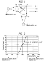
- an apparatus shown in Fig. 1 is known as an optical apparatus for projecting or receiving light in the same direction after separating or synthesizing light having a plurality of wavelengths.
- This optical apparatus is arranged such that rays of light from two light sources 1a and 1b having different wavelengths (wavelengths ⁇ 1 and ⁇ 2) are converted into parallel rays of light by means of collimator lenses 2a and 2b, respectively, and the rays of light are reflected or transmitted by using a dichroic mirror 2, which is an optical element, owing to differences in the wavelength, thereby synthesizing the light.
- a dichroic mirror 2 which is an optical element
- ⁇ 1 is set in a reflected-wavelength region (e.g., 700 nm) and ⁇ 2 in a transmitted-wavelength region (e.g., 900 nm)
- the two light waves are synthesized by the dichroic mirror, making it possible to project the light with the two wavelengths ( ⁇ 1 and ⁇ 2).
- the dichroic mirror As an optical filter used in this type of optical apparatus, one having a multilayered structure, called the dichroic mirror, is conventionally known.
- the dichroic mirror of this arrangement has the wavelength-transmittance characteristic such as the one shown in Fig. 3A.
- these material layers it is possible to cite TiO2 and SiO2.
- (1H, 1L)8 represents a group of repeatedly laminated material layers, indicating that 1H and 1L are repeated 8 times.
- the characteristic of the dichroic mirror serving as the optical filter the steeper the rising characteristic shown in Fig. 3A, the light having the closer two wavelengths can be separated or synthesized.
- An example in which the light with two wavelengths is synthesized by the dichroic mirror is shown in Fig. 4.
- the characteristic required of the dichroic mirror is that, as shown in Fig. 5, the reflectance is high (the transmittance is low) at the wavelength ⁇ 1, and the transmittance is high at the wavelength ⁇ 2.
- the power of the light with ⁇ 1 and the power of the light with ⁇ 2 can be synthesized efficiently into optical power after synthesis.
- a case where the light is separated on the basis of the difference in wavelength can be considered in utterly the same way. Accordingly, the steeper the rising characteristic, the closer the reflecting region and the transmitting region in Fig. 5 are, and it is possible to separate or synthesize the light having two closer wavelengths.
- the light is randomly polarized light in which a P polarized component and an S polarized component are randomly mixed, and since the transmittance characteristic becomes the average of the P polarized light and the S polarized light, so that a ripple occurs in the vicinity of a 50% transmitting region. Since the characteristic of the randomly polarized light becomes an average value of the characteristic of the P polarized light and the characteristic of the S polarized light, a ripple occurs where the transmittance is in the vicinity of 50% (in terms of the wavelength, in the vicinity of 740 nm in Fig. 6). It should be noted that Fig. 6 shows the characteristic in the case where the angle of incidence of the dichroic mirror is 70° in the conventional arrangement of the film.
- the wavelength spectrum characteristic is wide to a certain extent in the case of a light source such as an LED
- the difference between the refractive indices of the two material layers in the adjustment layer is made small (e.g., in the case of TiO2 and Al2O3 shown in Fig. 18 which will be referred to later)
- the nontransmitting band becomes narrow.
- the nontransmitting band located between "A" and "B.”
- the nontransmitting band is similar to the reflecting band shown in Fig. 5, and is related to the light reflected by the dichroic mirror. If consideration is given to a case in which the light with the wavelength ⁇ 1 is reflected in Figs. 4 and 5 referred to above, in the case of the conventional dichroic mirror (the angle of incidence: 45°) shown in Fig. 7, a wavelength falling between B (approx. 610 nm) to A (approx. 750 nm) can be selected as ⁇ 1. If the distance between B and A is short, the range from which the wavelength can be selected becomes the narrower.
- the wavelength spectrum is wide to a certain extent; therefore, if the distance between B and A is short, not all the light emitted from the LED can be reflected, resulting in a power loss (not all the light other than the light having wavelengths falling between B and A is reflected, and that light is transmitted in accordance with its transmittance). Accordingly, unless the distance between B and A is wide to a certain extent, it is impossible to efficiently separate or synthesize light with two wavelengths.
- the dichroic mirror of the present invention is comprised of a first portion including an H material layer having a high refractive index, and an M material layer having an intermediate refractive index, the H material layer and the M material layer being laminated repeatedly; and a second portion including an H material layer having a high refractive index, and an L material layer having a low refractive index, the H material layer and the L material layer being laminated repeatedly.
- the dichroic mirror is comprised of a first portion comprising a first material and a second material which have a first difference in a refractive index, the first and second materials being repeated with the same optical thickness, respectively; and a second portion comprising a third material and a fourth materials which have a second difference in a refractive index, the second difference being greater than the first difference.
- the dichroic mirror in accordance with the present invention through a combination of a repeatedly laminated portion of material layers having a small difference in the refractive index and material layers having a large difference in the refractive index, it is possible to suppress the occurrence of ripples in the transmittance characteristic and obtain a steep spectral characteristic and a wide nontransmitting-band characteristic.
- a plurality of light beams are emitted from light-emitting elements of a light-projecting section or light sources, and one of the light beams is reflected by the dichroic mirror, and the other light beam is transmitted therethrough, thereby synthesizing the light beams and allowing the beams to be projected onto an object to be detected.
- the reflected light from the object to be detected is received, it is possible to detect the presence or absence of the object to be detected, the distance thereto, a displacement and the like. Since the dichroic mirror is disposed in divergent optical paths from the light-emitting elements or the light sources, the optical system can be made compact.
- the dichroic mirror also acts to separate light beams having a plurality of wavelengths for receiving the light at a plurality of light-receiving sections, in which case, the dichroic mirror is disposed in convergent optical paths of the incident light, and the optical system is made compact.
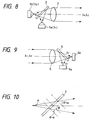
- Fig. 8 shows a projecting optical system of an optical apparatus in accordance with this embodiment.
- the optical apparatus is comprised of light sources (light-emitting elements such as light-emitting diodes) 1a and 1b for divergently emitting light with mutually different wavelengths ( ⁇ 1 and ⁇ 2) in a nonparallel manner, respectively; a dichroic mirror 3 which is disposed in the paths of these nonparallel rays of light, is provided with wavelength selectivity, and serves as an optical element for synthesizing the light by allowing the light to be reflected thereby or transmitted therethrough in accordance with the wavelengths; and a collimator lens 2 for converting the light synthesized by the dichroic mirror 3 into parallel rays of light.
- light sources light-emitting elements such as light-emitting diodes
- the light sources 1a and 1b are arranged such that the two bundles of rays travel toward the dichroic mirror 3 from different directions as nonparallel rays, one bundle of rays being made incident upon one surface of the dichroic mirror 3 and the other bundle of rays being made incident upon the other surface of the dichroic mirror 3. Further, the two bundles of rays which travel as nonparallel rays continue to travel as nonparallel rays even after being synthesized by the dichroic mirror 3.
- the following advantages can be obtained thanks to the above-described configuration.
- one collimator lens can be shared, and the number of component parts used can be reduced, thereby making the apparatus low in cost and compact.
- the dichroic mirror can be made compact and low in cost, leading to a compact apparatus.
- the present invention is similarly applicable to a receiving optical system as well, as shown in Fig. 9.
- the apparatus of the receiving optical system is comprised of a focusing lens 5; the dichroic mirror 3 disposed in the optical path for focusing by the focusing lens 5 and adapted to separate the light into two bundles of rays having different wavelengths; and light-receiving elements 6a and 6b for receiving the separated two bundles of rays, respectively.
- the dichroic mirror 3 disposed in the path of the nonparallel rays of light as described above.
- the angle of incidence has a range from ⁇ - a to ⁇ + a, as shown in Fig. 10.
- an optical multilayered film such as a dichroic mirror, if the angle of incidence changes by ⁇ , the amount of wavelength shift in the transmittance characteristic becomes a function of cos ⁇ .
- the amount of change of cos ⁇ from the central angle of incidence ⁇ to each angle of incidence ⁇ - a, ⁇ + a can be respectively expressed as (1) cos ⁇ - cos ( ⁇ - a) (2) cos ⁇ - cos ( ⁇ + a)
- an angle X which is determined from cos ⁇ 1 ⁇ (2 cos a - 1)cos ⁇ becomes the center of the amount of the wavelength shift in the transmittance characteristic when the angle of incidence changes in the range from ( ⁇ - a) to ( ⁇ + a).
- the dichroic mirror is designed such that the transmittance in the case of a ( ⁇ 1 + ⁇ 2)/2 wavelength at the angle of incidence, X, becomes 1/2 of a maximum transmittance.
- Fig. 11 shows the transmittance characteristic of the dichroic mirror which is capable of efficiently separating or synthesizing the light with a wavelength of 700 nm and the light with a wavelength of 900 nm. As shown in Fig.
- a wavelength ⁇ D when the transmittance with the central angle of incidence ⁇ ( 45°) becomes virtually 1/2 of the maximum transmittance is ( ⁇ 1 + ⁇ 2)/2 , and is greater than 800 nm in this example.
- the angle-of-incidence dependence characteristic of the dichroic mirror in the conventional example shown in Fig. 1 is illustrated in Fig. 13.
- the dichroic mirror is disposed in the path of parallel rays of light (the angle of incidence: 45°), and is designed in such a manner as to be capable of efficiently separating or synthesizing the light with a wavelength of 700 nm and the light with a wavelength of 900 nm (since it is placed in the path of parallel rays of light, the angle of incidence is 45° only).
- the transmittance 50%.
- the light with the wavelength of 700 nm at an angle of incidence of 65° cannot be reflected efficiently.
- the light at the angle of incidence of 65° undergoes a large change in the transmittance with respect to the wavelength in the vicinity of the wavelength of 700 nm, there is a problem in that the intensity of the reflected light changes in the case where the spectrum of the light source has undergone a wavelength shift due to a change in the temperature or the like.
- the light with the wavelength of 700 nm has a sufficiently small transmittance even at the angle of incidence of 65°, and does not undergo such a problem.
- the transmittance becomes low when the angle of incidence is 65°
- the light at the angle of incidence of 65° has a small change with respect to the wavelength in the vicinity of the wavelength of 900 nm, so that no problem is presented in both the conventional example and this embodiment.
- the two bundles of nonparallel rays having two close wavelengths which could not be efficiently separated or synthesized in a conventional design, can be efficiently separated or synthesized.
- the thickness of each layer is preset (if the characteristic of a designed dichroic mirror, for example, is considered)
- the behavior of the change of the characteristic differs between the short wavelength side and the long wavelength side with respect to a design wavelength ⁇ D.
- the rate of change of the characteristic in the case of ⁇ D - ⁇ and ⁇ D + ⁇ is considered, since the rate of change is determined by the ratio with respect to the film thickness, the characteristic conceivably changes at a rate of ⁇ D - ⁇ / ⁇ D and ⁇ D + ⁇ / ⁇ D , respectively.
- the rate of change of the characteristic is determined by the relative wavelength with respect to ⁇ D, i.e., the ratio of wavelengths
- the wavelength at which the change becomes equal with respect to both wavelengths when ⁇ 1 and ⁇ 2 are given can be determined from ⁇ ( ⁇ 1 ⁇ 2).
- the concept is that it is desirable to set this wavelength as the center. If such a design is made, the aforementioned problem becomes more noticeable.
- the dichroic mirror having the characteristic shown in Fig. 11 referred to above the aforementioned problem can be alleviated substantially.
- the LED has a distribution of wavelengths of emitted light, such as those shown in Figs. 14A and 14B, so that the light separation/synthesis characteristic of the dichroic mirror having the characteristic shown in Fig. 11 or Fig. 13 is determined by taking into account the emission intensity and transmittance (reflectance) with respect to each wavelength in the distribution of the wavelengths of the emitted light. In this case as well, more efficient separation or synthesis can be attained in accordance with this embodiment than in accordance with the conventional art.
- a long-wavelength transmitting filter for reflecting the short wavelength side and transmitting the long wavelength side has been shown as the dichroic mirror in accordance with the above-described embodiment
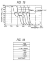
- the present invention is similarly applicable to a short-wavelength transmitting filter for transmitting the short wavelength side and reflecting the long wavelength side, as shown in Fig. 15.
- the phenomenon illustrated in the above-described embodiment becomes noticeable when the angle of incidence is large. Further, if the reduction of the size of the apparatus and the ease of designing the apparatus are taken into consideration, it is desirable to set the central angle of incidence in the vicinity of 45°.
- the dichroic mirror should be preferably be one which does not suffer losses such as the absorption of the light. Accordingly, the optical multilayered film of the dichroic mirror should preferably be formed of a dielectric multilayered film which is practically free from the absorption of the light.
- the projecting optical system shown in Fig. 8 referred to above it is possible to make compact an object detecting apparatus for detecting an object by receiving the light reflected by a reflecting plate and by detecting a change in the amount of the light received as the reflected light is shielded by the object being detected, as well as light-projecting sections of other photoelectric sensors.
- the separation or synthesis of two wavelengths is conducted at two or more locations, it becomes possible to separate or synthesize of three or more wavelengths.
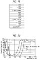
- the dichroic mirror of this arrangement has the wavelength-transmittance characteristic such as the one shown in Fig. 17.
- H,” “L,” and “M” represent material layers having a high refractive index, a low refractive index, and an intermediate refractive index, respectively, (e.g., 2.26, 1.46, and 1.67).
- these material layers it is possible to cite TiO2, SiO2, and Al2O3.
- the difference in the refractive index in the group (a first portion) of repeatedly laminated layers is made smaller, and the difference in the refractive index in other adjustment layers (second portions) is made larger.
- the range is 100 nm in Fig. 3A referred to above, whereas the range is 80 nm in Fig. 17, so that an improvement has been made. Accordingly, it is possible to separate or synthesize the light having two closer wavelengths than in accordance with the conventional design.
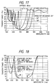
- Fig. 18 shows, in conjunction with this embodiment, the characteristic at the angle of incidence of 20° of the dichroic mirror optimally designed by using only TiO2 and Al2O3 in addition to the above case.
- the nontransmitting band (B' - A') expands in the case where the film is comprised of TiO2, Al2O3, and SiO2 (the adjustment layers are comprised of TiO2 and SiO2, while the group of repeated layers is comprised of TiO2 and Al2O3) as compared to the case where the film is comprised of only TiO2 and Al2O3 (the adjustment layers are also comprised of TiO2 and Al2O3).
- the steepness of its characteristic is generally determined mainly by the difference in the refractive index of the group of repeated layers and the number of repeated times, and the range of the nontransmitting band is determined by the difference in the refractive index of the so-called adjustment layers. Accordingly, by causing the group of repeated layers to be comprised of TiO2 and Al2O3 and the adjustment layers to be comprised of TiO2 and SiO2, it is possible to obtain a steeper characteristic than in the case where the film is comprised of only TiO2 and SiO2, and to obtain a wider nontransmitting band than in the case where the film is comprised of only TiO2 and Al2O3.
- the film is formed by repeating the layers of the same optical thickness, it is possible to nonuniformly design part or all of the thicknesses of the layers such that the optical thicknesses of the respective layers become optimal, instead of repeating the layers of the same optical thickness.
- materials TiO2 which can be easily formed into a film has been selected as a high-refractive-index material for obtaining a large difference in the refractive index in the adjustment layers, and SiO2 has been similarly selected as a low-refractive-index material.
- MgFe is conceivable as a material having a lower refractive index, but if this material is used in the multilayer, cracks and the like are liable to occur since the stress occurring at the time of film formation acts in the same direction as in the case of TiO2. Also, TiO2 and Al2O3 have been selected for the group of repeated layers so as to obtain an appropriate difference in the refractive index. By using the high-refractive-index material TiO2 for both the adjustment layers and the group of repeated layers, design and fabrication can be effected easily.
- n 1.28L
- 1.33H 0.63L, 1.25H, 0.87L, (1.15H, 1.06M)5
- 1.01H, 1.63L, 0.17H / air (n 1) ... film composition (2)
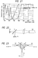
- it is possible to further expand the nontransmitting band as compared to the composition (1), as shown in Fig. 20.
- the configuration of this embodiment was obtained as follows.
- Fig. 21 shows the characteristic at the angle of incidence of 45° in the composition (1).
- the nontransmitting band with the wavelength ranging from 600 nm to 700 nm is not located in the vicinity of 0%. Accordingly, by combining the group of laminated layers having the characteristic (A) shown in Fig.
- the nontransmitting band with the wavelength ranging from 600 nm to 700 nm can be set in the vicinity of 0%, as shown in Fig. 20.
- the film composition for obtaining the characteristic (A) is basically the same as the composition (1), and the design wavelength is set to be short (i.e., the optical film thickness is made thin).
- the film composition for obtaining the characteristic (A) may include the group of repeated layers as in the composition (1), or may be obtained by optimally designing the optical thicknesses of the respective layers, as described before.
- the characteristic (A) is obtained by the "1.28L, 0.45H, ..., 1.33H, 0.63L” portion on the substrate side of the film composition, while the characteristic (1) is obtained by the "1.25H, 0.87L, ..., 1.63L, 0.17H” portion.
- the portion of the film for obtaining the characteristic (A) is comprised of only TiO2 and SiO2. This is because since the directions of the stress acting during film formation are opposite for TiO2 and SiO2, a multilayer can be realized easily.
- the portion of the film concerning the characteristic (A) is comprised of TiO2 and SiO2 which can be formed into a multilayer relatively easily.
- the setting and the like of the adjustment layers can be designed appropriately by adopting the technique of computer simulation or the like, and various film compositions are possible.
- the dichroic mirror with a nontransmitting band displaying a steep characteristic is very effective in the case where it is disposed in paths of nonparallel rays in a projecting optical system, as shown in Fig. 8 referred to above.
- the angle of incidence is small, there is no difference between the transmittance characteristics of the P polarized light and the S polarized light, and in this case a steep characteristic is obtained by forming the group of repeated layers by substance layers having large refractive indices.
- the present invention is effective when the angle of incidence is large to a certain extent or more.
- the central angle of incidence is set at 45° by taking the ease of use and the like into consideration.
- the present invention can be implemented in a similar manner as a short-wavelength transmitting filter as well.
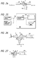
- Fig. 22 shows a configuration in a case where the present invention is carried out in a wavelength multiplex communication system.
- an arrangement is provided such that after the light from the light-emitting element 1a for emitting the light with the wavelength ⁇ 1 and the light from the light-emitting element 1b for emitting the light with the wavelength ⁇ 2 are synthesized by the dichroic mirror 3, the light is focused by a lens 4 and is supplied to an optical fiber cable 100. If such an arrangement is provided, it becomes possible to transmit the light having a plurality of wavelengths through the optical fiber cable 100. In this case, if the light of each wavelength is modulated by desired information, the multiplexing of information can be effected easily.
- Fig. 23 shows a configuration of a conventional optical apparatus of this type, in which three lenses 4 are disposed among an optical fiber 101 for transmitting light with wavelengths ⁇ 1 and ⁇ 2, an optical fiber 102 for transmitting light with the wavelength ⁇ 1, and an optical fiber 103 for transmitting light with the ⁇ 2, and the conventional dichroic mirror 3 (optical element) is disposed in the paths of parallel rays of light.
- Fig. 24 shows a configuration of an optical apparatus in accordance with this embodiment, and since the dichroic mirror 3 in this embodiment is disposed in the paths of nonparallel rays of light, only one lens 4 is provided.
- the light is emitted from an end face of the optical fiber 101 for transmitting the light with the wavelengths ⁇ 1 and ⁇ 2.
- the light is separated into the light with the wavelengths ⁇ 1 and ⁇ 2 by the dichroic mirror 3 in accordance with this embodiment, and is respectively guided by the optical fibers 102 and 103, and is transmitted.
- the light with the wavelengths ⁇ 1 and ⁇ 2 emitted from the end faces of the optical fibers 102 and 103 is synthesized substantially coaxially by the dichroic mirror 3, and is passed through the focusing lens 4 and is guided by the optical fiber 101.
- Fig. 25 shows a configuration of a further embodiment.
- visual information of such as CATV or the like is multiplexed on a telephone line conducting communication using the optical fiber 100 and is transmitted, and the optical fiber 100 is branched by a branching device 202 within a home 201 to allow the visual images to be transmitted to a TV set 203 and messages on the telephone line to be transmitted to a telephone 204.
- the optical apparatus using the dichroic mirror in accordance with this embodiment can be applied to the branching device 102.
- this embodiment in contrast to the fact that three lenses are conventionally used, only one lens can be used, as described before, so that the apparatus can be made compact and low in cost.
- Fig. 26 shows a configuration of a conventional optical apparatus of this type which transmits the light with the wavelength ⁇ 1 from the light-emitting element 1 through the optical fiber 100 and receives by a light-receiving element 6 the light with the ⁇ 2 transmitted thereto through the optical fiber 100.
- the dichroic mirror 3 is disposed in the paths of parallel rays of light by using three lenses.
- FIG. 27 shows an optical apparatus in accordance with this embodiment, which is arranged such that the dichroic mirror 3 in this embodiment is disposed in paths of nonparallel rays of light, and only one lens 4 is used.
- the apparatus can be made more compact and lower in cost as compared to the conventional configuration.
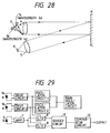
- Fig. 28 shows a configuration of the reflection-type photoelectric sensor.
- the light-projecting section of the sensor is comprised of the light sources 1a and 1b for respectively emitting light with mutually different wavelengths ⁇ 1 and ⁇ 2, and the dichroic mirror 3 in accordance with the present invention and the light-projecting lens 4 which are disposed in their divergent optical paths.
- the light-projecting section projects light through the light-projecting lens 4 toward an object M to be detected.
- the light-receiving section receives the light reflected from the object M to be detected by the light-receiving element 6 via the light-receiving lens 5.
- the signal processing circuit of this photoelectric sensor is shown in Fig. 29.
- the light sources 1a and 1b are made to emit light alternately in a time-sharing manner by the use of oscillator circuits and drive circuits.
- An output signal from the light-receiving element 6 is amplified by an amplifier 7, and the amount of reflected light of each wavelength is detected in synchronism with the emission of light from each light source by using a pair of sample-and-hold circuits 8.
- a ratio between the amount of the two reflected beams of light having different wavelengths is calculated by a divider circuit 9, and a comparator circuit 10 is used to make a comparison as to whether that value is greater than or smaller than a predetermined threshold value, so as to detect the presence or absence of an object to be detected having a particular color.
- the overall projecting optical system can be made compact, with the result that the apparatus can be made compact and low in cost.
- the dichroic mirror 3 generally has angle-of-incidence dependence. Accordingly, if the numerical apertures NA in the x- and y-axis directions are the same, the distribution of intensity of the projected beam becomes asymmetrical in the x-axis direction. If the intensity distribution is asymmetrical, when, for example, a moving object is detected, there are cases where the detecting timing differs. Accordingly, by providing an arrangement in which NA in the x-direction is small and NA in the y-direction is large, the distribution of intensity of the projected beam can be made close to vertical and horizontal symmetry. Hence, it is possible to prevent a difference in the detection timing.
- the light source having a shorter wavelength is set as the light source 1a on the side where the light is reflected by the dichroic mirror 3, and the light source having a longer wavelength is set as the light source 1b on the side where the light is transmitted by the dichroic mirror 3.
- one having a shorter wavelength generally has smaller maximum emission power, so that if the effective use of power of emission of light toward an object to be detected is considered, the light source having the shorter wavelength is desirably used on the reflecting side rather than on the transmitting side where a power loss occurs due to Fresnel reflection.
- the two projected light beams are difficult to be completely aligned with each other owing to factors in fabrication such as the positional offset of the two light sources 1a and 1b and the angular deviation and positional offset of the dichroic mirror 3.
- the positional offset of the dichroic mirror 3 constitutes an offset only in a direction parallel to a plane where the respective optical axes extending from the two light sources 1a and 1b to the dichroic mirror 3 are present, and the other factors constitute offsets in both perpendicular and parallel directions.
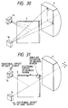
- the misalignment of the two projected beams becomes greater in the direction parallel to the plane where the optical axes of the light sources are present rather than in the direction perpendicular thereto. Accordingly, in a case where the object to be detected which is moving perpendicular to the direction of the projected beam is detected, if the sensor is arranged such that the plane where the axes of the light sources are present becomes perpendicular to the moving direction of the object M to be detected, as shown in Fig. 32, it becomes possible to detect the object M to be detected without erroneous operation even in a state in which the overall projected beam is not completely applied to the object M to be detected.
- the respective optical axes from two or more light sources to the optical element, the optical axis from the projecting section to the object to be detected, and the optical axis from the object to be detected to the light-receiving section are located in the same plane, so as to detect the object to be detected which moves perpendicular to the direction of the projected beam. That is, the sensor is arranged such that the plane where the three optical axes are present is perpendicular to the moving direction of the object to be detected.
- the fields of view of the projected beam and the light-receiving section in this case are shown in Fig. 33.
- the objects to be detected are moving in the plane where the three optical axes are present, as indicated by the arrows in the drawing unlike in the aforementioned moving direction, objects M1 and M2 to be detected are detected at different positions with respect to the moving direction as shown in the drawing owing to the distance between the objects M1 and M2 to be detected, which is inconvenient.
- the detecting position does not change due to the distance between the objects to be detected.
- the present invention is implemented as the reflection-type photoelectric sensor.
- the configuration of the optical system is the same as that of the above-described embodiment, and a light source emitting red light is used as the light source 1a and a light source emitting infrared light is used as the light source 1b.
- the signal processing circuit as shown in Fig 34, the two light sources 1a and 1b are made to emit light simultaneously, the output signal from the light-receiving element 6 is amplified, the signal is subjected to sample and hold (S/H) at the emission timing, and a comparison is made by the comparator circuit 10 to determine whether the value is greater or smaller than a threshold value, so as to detect the presence or absence of the object to be detected.
- the senor is designed such that the formula ( ⁇ 2/2) > ( ⁇ 1/2) + ⁇ d is satisfied where the angle of divergence of the red projected beam is ⁇ 1, the angle of divergence of the infrared projected beam is ⁇ 2, and the angular deviation between the optical axes of the red light and the infrared light is ⁇ d.
- the optical path length from the light source 1b to the light-projecting lens 4 is made shorter than the optical path length from the light source 1a to the light-projecting lens 4, so as to make the angle of divergence of the infrared projected beam larger than that of the red projected beam.
- the light-projecting section is so arranged that it has the light sources 1a and 1b for emitting light with the wavelengths ⁇ 1 and ⁇ 2, respectively, the light from the light source 1a is reflected by the dichroic mirror 3 in the divergent optical path, and the light from the light source 1b is transmitted therethrough to synthesize the light from the two light sources, allowing the light to be projected onto the object M to be detected by means of the light-projecting lens 4.
- the light-receiving section is so arranged that the light reflected from the object M to be detected is received by the light-receiving element 6 via the light-receiving lens 5.
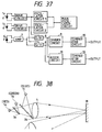
- the light sources 1a and 1b are made to emit light alternately in a time-sharing manner, the amounts of reflected light having the respective wavelengths are detected from the output signal from the light-receiving element 6 in synchronism with the emission of light from the light sources 1a and 1b by using a processing circuit such the one shown in Fig. 37, a ratio therebetween is calculated by the divider circuit 9, and the calculated result is compared with a threshold value by the comparator circuit 10, so as to detect a mark on the object M to be detected.
- the mark sensor apparatus using two wavelengths in accordance with this embodiment, as compared with a mark sensor using one wavelength, detection is possible if the color of the object to be detected has a reflectance different from that of a substrate concerning either one of the two beams of light having different wavelengths, so that the number of kinds of detectable marks increases.
- the colors of the substrate and the mark of the object to be detected are a combination of black and white
- the ratios of the reflected-light signals of the two wavelengths for the substrate and the mark become substantially the same, but by determining the sum of the amounts of the two reflected beams by using an adder circuit 11, it is possible to detect the mark.
- the light-projecting section is arranged such that it has light sources 1a, 1b, and 1c for emitting red, green, and blue light, respectively, the light from the light source 1a is transmitted through a dichroic mirror 3a in the divergent optical path, the light from the light source 1b is reflected thereby so as to synthesize the two beams, the synthesized light is transmitted through a dichroic mirror 3b, and the light from the light source 1c is reflected thereby to synthesize the light, so as to project the light onto the object M to be detected by means of the light-projecting lens 4.
- the light-receiving section is arranged such that the light reflected from the object M to be detected is received via the light-receiving lens 5 by a color sensor 60 having sensitivity to red light, green light, and blue light, respectively.
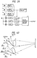
- the signal processing circuit of this color discriminating apparatus is shown in Fig. 39.
- the amounts of received light having respective wavelengths are detected from the output of the color sensor 60 in synchronism with the emission timing, and the color of the object M to be detected is discriminated by a color discriminating circuit 13.
- Fig. 40 shows another embodiment of the color discriminating apparatus.
- the reflected light having three wavelengths, red, green, and blue, is separated, and the light with the respective wavelengths is received by light-receiving elements 6a, 6b, and 6c.
- an arrangement may be provided such that, as shown in Figs.
- three light sources are made to emit light in a time-sharing manner, the light is received by a single light-receiving element in the light-receiving section, and the amounts of reflected light having the respective wavelengths are detected in synchronism with the emission timing of the respective light sources.
- Fig. 41 shows an example in which the present invention is applied to a color discriminating sensor.
- a red light source is used as the light-emitting element 1a
- a green light source is used as the light-emitting element 1b
- a blue light source is used as the light-emitting element 1c.
- the output light from the light-emitting element 1a and the light-emitting element 1b is synthesized by the dichroic mirror 3a, and the synthesized light and the light emitted from the light-emitting element 1c are synthesized by the dichroic mirror 3b.
- the synthesized light is focused by the lens 4 onto the object M, and the light reflected from the object M is focused by means of the lens 5, is diffracted by a diffraction grating 5a, and is detected by a light-receiving-element array 6a. If such an arrangement is adopted, the color of the object can be discriminated on the basis of the difference in intensity between the wavelengths of the reflected light or a ratio of intensity therebetween. Since the diffraction grating 5a exhibits a different angle of diffraction depending on the wavelength, so that the diffraction grating 5a is capable of receiving the light by separating the light for each wavelength. As for the dichroic mirrors 3a and 3b, apart from the plate-shaped ones shown in the drawing, it is possible to use cube-shaped or prism-shaped ones.
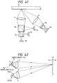
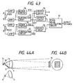
- Fig. 42 shows an example in which the present invention is carried out as a distance measuring sensor.
- the light-projecting section is so arranged that it has the light sources 1a and 1b for emitting light with the wavelengths ⁇ 1 and ⁇ 2, respectively, the light from the light source 1a is reflected in the divergent optical path by means of the dichroic mirror 3, the light from the light source 1b is transmitted therethrough so as to be synthesized, and the light is projected onto the object M to be detected by means of the light-projecting lens 4.
- the light-receiving section is so arranged that the light reflected from the object M to be detected is separated into two wavelengths by the dichroic mirror 3 similar to the light-projecting section via the light-receiving lens 5, and is received by position-detecting elements PSD1 and PSD2, respectively.
- the positions of spots on the position-detecting elements PSD1 and PSD2, which correspond to the distance to the object M to be detected, are detected by the trigonometrical distance measurement method, so as to detect the distance to the object M to be detected.
- the signal processing circuit of the distance measuring sensor is shown in Fig. 43.
- This circuit is comprised of adder circuits 14, subtracter circuits 15, divider circuits 16, a mean-value calculating circuit 17, and the like, and is capable of detecting a color in addition to distance measurement.
- the color detection is effected by a ratio VS1/VS2 between the sum VS1 of two outputs of the position-detecting element PSD1 and the sum VS2 of two outputs of the position-detecting element PSD2.
- the distance measurement is effected by an average of VS1/VD1 which is the sum/difference of the two outputs of the position-detecting element PSD1 and VS2/VD2 which is the sum/difference of the two outputs of the position-detecting element PSD2.
- the position-detecting elements are used as the light-receiving elements, the present invention can be realized by using light-receiving elements split into two or more.
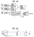
- the light-projecting section is so arranged that it has the light sources 1a and 1b for emitting light with the wavelengths ⁇ 1 and ⁇ 2, respectively, the light from the light source 1a is reflected in the divergent optical path by means of the dichroic mirror 3, the light from the light source 1b is transmitted therethrough so as to be synthesized, and the light is projected onto the object M to be detected by means of the light-projecting lens 4.
- the two projected beams are concentric with one angle of divergence being smaller than the other.
- the light source having the shorter wavelength of the two beams having different wavelengths is desirably provided with a smaller angle of divergence.
- the light-receiving section is so arranged that the light reflected from the object M to be detected is received by the light-receiving element 6 via the light-receiving lens 5.
- the signal processing circuit of this shape-recognizing sensor is shown in Fig. 45.
- the two light sources 1a and 1b are made to emit light alternately in a time-sharing manner, and after the output signal from the light-receiving element 6 is amplified by the amplifier 7, the amounts of reflected light with the respective wavelengths are detected in synchronism with the emission of the light from the light sources, and a ratio between the two amounts of reflected light is determined by the divider circuit 9.
- the object M to be detected has a size greater than the projected beam having a greater angle of divergence, P1/P2 becomes virtually 1, and if the object M to be detected has a size falling between the projected beam having the greater angle of divergence and the projected beam having the smaller angle of divergence, the smaller the object M to be detected, the smaller P1/P2 becomes. Accordingly, it is possible to detect the size of the object M to be detected through the ratio P1/P2.
- the present invention is not limited to the same, and can be similarly applied to a transmission-type sensor for receiving the light which was not shielded by the object M to be detected.
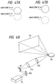
- the reflection-type or the transmission-type sensor if an arrangement is provided such that, as shown in Fig. 47, two projected beams having different wavelengths are projected by being offset from each other, in both cases where portions of the spots overlap with each other and cases where there are no overlapping portions, the position of the object to be detected, i.e., the size or shape in the deviating direction of the object to be detected, can be determined by detecting which of the projected spots has a large amount of received light.
- Fig. 48 shows an example in which the present invention is applied to a laser display.
- a light source device 24 is provided in which three laser beams of red, green, and blue are synthesized by being subjected to intensity modulation by unillustrated optical modulators by means of tricolor signals of color television.
- the light sent from the light source device 24 is reflected by a reflecting mirror 25a, and is led to a galvanometer 26.
- the synthesis of the light can be effected by using, for example, dichroic mirrors.
- the galvanometer 26 effects scanning in the vertical direction, while a rotating polygonal mirror 28 effects scanning in the horizontal direction.
- two relay lenses 27a and 27b are used for improving the frequency response by making optical deflectors small, the deflectors are located at the respective focal points, and the two lenses are arranged such that the distance therebetween becomes the sum of the two focal lengths. If the light scanned by the rotating polygonal mirror 28 is projected onto a screen 29, a display for color television having high resolution and saturation is obtained.
- Fig. 49 shows an example in which the present invention is applied to a color image scanner.
- an input scanning unit 30 and an output scanning unit 31 are rotated by being synchronized with each other by a synchronization unit 32.
- a color original 36 placed on the input scanning unit 30 is scanned by a color discrimination sensor 33 such as the one shown in Fig. 41, and that information is sent to a computer 34.
- the computer 34 controls a light source 35 on the basis of the scanned result supplied thereto, and records a color image on a recording material 37 in the output scanning unit 31.
- Fig. 50 shows an example in which the present invention is applied to a two-wavelength optical head.
- outputs from the light-emitting elements 1a and 1b for emitting light having different wavelengths are synthesized by the dichroic mirror 3, and the synthesized light is applied to an optical disk 42 via a polarized-beam splitter 40 and a lens 41, so as to effect the direct overwriting and parallel reading of data.
- processing in writing data to the optical disk 42 is delayed since writing needs to be effected by waiting for the disk 42 to rotate after the bits are erased once.
- direct overwriting can be effected, high-speed processing can be effected.
- In reading on the other hand, since information in two track grooves can be read simultaneously, high-speed reading becomes possible.
- the arrangement provided is such that a dichroic mirror which has a multilayered structure for synthesizing or separating light beams with different wavelengths and exhibiting low angle-of-incidence dependence is disposed in divergent or convergent optical paths, i.e., paths of nonparallel rays of light, and the light is reflected or transmitted in accordance with the wavelength, so as to synthesize or separate the light beams. Accordingly, as compared with the conventional case where the optical elements are disposed in the paths of parallel rays of light, it is possible to make the apparatus compact, reduce the number of component parts used, and lower the cost.
- the conventional dichroic mirror if the angle of incidence changes in the paths of nonparallel rays of light, cases can occur in which the light with the wavelength to be reflected is transmitted without being reflected, with the result that the conventional dichroic mirror could be used only in the paths of parallel rays of light.
- the dichroic mirror since the angle-of-incidence dependence is made low, the dichroic mirror can be used in the paths of nonparallel rays of light, so that the above-described advantage can be obtained.
- a material layer having a small difference in the refractive index is selected as a repeatedly laminated portion, while, in layers other than the repeated layer, a material layer having a large difference in the refractive index is selected as an adjustment layer for adjusting ripples occurring in the transmittance characteristic. Since these layers are combined, it is possible to obtain a steep spectral characteristic and a wide nontransmitting-band characteristic. Accordingly, it is possible to reliably synthesize or separate two light beams having close wavelengths.
- the arrangement provided is such that the light from two light sources having different wavelengths is synthesized by a dichroic mirror in the divergent optical paths, and is projected onto an object to be detected by means of a light-projecting lens, or the light is separated by a dichroic mirror in the convergent paths of two light beams having different wavelengths. Therefore, as compared with a conventional apparatus, one light-projecting lens can be shared instead of using two light-projecting lenses, and the optical members can be made compact, making the overall projecting optical system compact. Hence, it is possible to realize a low-cost and compact apparatus.
- the dichroic mirror having the optical multilayered film structure of the present invention the light from one light source is reflected, while the other light is transmitted. Since the reflected light is not transmitted through the substrate of the optical member, a beam which is free of aberrations can be projected onto the object to be detected, and it is possible to effect the detection of an object on a stable basis. Hence, an error does not occur in the detection of the position of the object to be detected, and the apparatus of the invention can be used as a reflection-type sensor and a transmission-type sensor. Moreover, it is possible to effect the discrimination of a color in addition to the detection of the shape and the presence or absence of the object to be detected and the distance to the object to be detected.
Landscapes
- Physics & Mathematics (AREA)
- General Physics & Mathematics (AREA)
- Optics & Photonics (AREA)
- Chemical & Material Sciences (AREA)
- Inorganic Chemistry (AREA)
- Optical Filters (AREA)
- Length Measuring Devices By Optical Means (AREA)
- Optical Elements Other Than Lenses (AREA)
Applications Claiming Priority (6)
| Application Number | Priority Date | Filing Date | Title |
|---|---|---|---|
| JP10212494 | 1994-04-14 | ||
| JP10212694 | 1994-04-14 | ||
| JP102124/94 | 1994-04-14 | ||
| JP10212694 | 1994-04-14 | ||
| JP102126/94 | 1994-04-14 | ||
| JP10212494 | 1994-04-14 |
Publications (3)
| Publication Number | Publication Date |
|---|---|
| EP0677755A2 true EP0677755A2 (fr) | 1995-10-18 |
| EP0677755A3 EP0677755A3 (fr) | 1996-02-14 |
| EP0677755B1 EP0677755B1 (fr) | 2001-07-18 |
Family
ID=26442857
Family Applications (1)
| Application Number | Title | Priority Date | Filing Date |
|---|---|---|---|
| EP95105664A Expired - Lifetime EP0677755B1 (fr) | 1994-04-14 | 1995-04-13 | Miroir dichroique pour séparer/synthétiser de la lumière composée de plusieurs longueurs d'ondes et dispositif optique et procédé de détection utilisant ce miroir |
Country Status (4)
| Country | Link |
|---|---|
| US (2) | US5600487A (fr) |
| EP (1) | EP0677755B1 (fr) |
| KR (1) | KR100219016B1 (fr) |
| DE (1) | DE69521736T2 (fr) |
Cited By (3)
| Publication number | Priority date | Publication date | Assignee | Title |
|---|---|---|---|---|
| GB2326489A (en) * | 1997-03-25 | 1998-12-23 | Glaverbel | Dichromatic mirror |
| EP0959325A3 (fr) * | 1998-05-20 | 2001-01-24 | Keyence Corporation | Commutateur photo-électrique, commutateur photo-électrique à fibre optique et détecteur distinguant les couleurs |
| EP1111333A4 (fr) * | 1999-06-29 | 2002-08-28 | Omron Tateisi Electronics Co | Dispositif a source lumineuse, spectroscope comportant le dispositif a source lumineuse et capteur d'epaisseur de couche |
Families Citing this family (56)
| Publication number | Priority date | Publication date | Assignee | Title |
|---|---|---|---|---|
| JPH0968663A (ja) * | 1995-09-04 | 1997-03-11 | Brother Ind Ltd | 走査光学装置 |
| US5914817A (en) * | 1998-05-15 | 1999-06-22 | Optical Coating Laboratory, Inc. | Thin film dichroic color separation filters for color splitters in liquid crystal display systems |
| BR9915829A (pt) | 1998-11-02 | 2001-11-13 | Code 3 Inc | Luz de alerta para veìculo dotada de um elementodicróico |
| US6595669B2 (en) | 1998-11-02 | 2003-07-22 | Code 3, Inc. | Vehicular warning light having less apparent color when not energized |
| JP3332879B2 (ja) * | 1998-12-02 | 2002-10-07 | キヤノン株式会社 | ダイクロイックミラー |
| US6295173B1 (en) | 1998-12-18 | 2001-09-25 | Unaxis Balzers Aktiengesellschaft | Configuration for color division and/our recombination |
| US6252719B1 (en) * | 1999-03-19 | 2001-06-26 | Lucent Technologies Inc. | Beam splitter/combiner module |
| US6398364B1 (en) | 1999-10-06 | 2002-06-04 | Optical Coating Laboratory, Inc. | Off-axis image projection display system |
| US6456414B1 (en) | 2000-08-15 | 2002-09-24 | The United States Of America As Represented By The Secretary Of The Navy | Sequential color scanner |
| CH694184A5 (fr) * | 2000-12-27 | 2004-08-31 | Bobst Sa | Dispositif de lecture de marques de rep'rage dans une machine d'impression polychrome. |
| EP1467263A4 (fr) * | 2002-01-16 | 2009-12-16 | Japan Science & Tech Agency | Dispositif de reproduction holographique d'images mobiles et dispositif de reproduction holographique d'images mobiles couleur |
| SE524655C2 (sv) * | 2002-06-19 | 2004-09-14 | Trimble Ab | Elektronisk avstånds- och vinkelmätningsanordning |
| JP4028551B2 (ja) * | 2002-10-10 | 2007-12-26 | 松下電器産業株式会社 | 照明装置、照明装置システム、照明方法、プログラム、および記録媒体 |
| US6896381B2 (en) * | 2002-10-11 | 2005-05-24 | Light Prescriptions Innovators, Llc | Compact folded-optics illumination lens |
| US7377671B2 (en) * | 2003-02-04 | 2008-05-27 | Light Prescriptions Innovators, Llc | Etendue-squeezing illumination optics |
| US7329029B2 (en) * | 2003-05-13 | 2008-02-12 | Light Prescriptions Innovators, Llc | Optical device for LED-based lamp |
| US8075147B2 (en) * | 2003-05-13 | 2011-12-13 | Light Prescriptions Innovators, Llc | Optical device for LED-based lamp |
| WO2005012951A2 (fr) * | 2003-07-28 | 2005-02-10 | Light Prescriptions Innovators, Llc | Procede de generation simultanee de surfaces tridimensionnelles multiples et optiques d'eclairage de forme libre conçues a partir dudit procede |
| JP4109174B2 (ja) * | 2003-09-17 | 2008-07-02 | 浜松ホトニクス株式会社 | 分光装置 |
| WO2005050262A2 (fr) * | 2003-11-14 | 2005-06-02 | Light Prescriptions Innovators, Llc | Combineur de faisceau dichroique utilisant une del bleue a phosphore vert |
| US7618162B1 (en) * | 2004-11-12 | 2009-11-17 | Inteled Corp. | Irradiance-redistribution lens and its applications to LED downlights |
| US8631787B2 (en) * | 2005-07-28 | 2014-01-21 | Light Prescriptions Innovators, Llc | Multi-junction solar cells with a homogenizer system and coupled non-imaging light concentrator |
| US8419232B2 (en) * | 2005-07-28 | 2013-04-16 | Light Prescriptions Innovators, Llc | Free-form lenticular optical elements and their application to condensers and headlamps |
| EP1910736A4 (fr) * | 2005-07-28 | 2010-05-26 | Light Prescriptions Innovators | Optique d'eclairage a conservation d'etendue pour systemes d'eclairage par l'arriere et d'eclairage par l'avant |
| EP2064487A4 (fr) * | 2006-07-14 | 2010-09-01 | Light Prescriptions Innovators | Film améliorant la luminosité |
| EP2057409A2 (fr) * | 2006-08-10 | 2009-05-13 | Light Prescriptions Innovators, LLC. | Recyclage de lumiere led pour amelioration de la luminance et retrecissement angulaire |
| WO2008022065A2 (fr) * | 2006-08-11 | 2008-02-21 | Light Prescriptions Innovators, Llc | Amélioration de luminance de led et mélange de couleurs par combinaison de faisceau multiplexée de manière rotative |
| US20080048956A1 (en) * | 2006-08-22 | 2008-02-28 | Texas Instruments Incorporated | Color management system and method for a visual display apparatus |
| US8736959B2 (en) * | 2007-08-12 | 2014-05-27 | Toyota Motor Engineering & Manufacturing North America, Inc. | Omnidirectional reflector |
| US10870740B2 (en) | 2007-08-12 | 2020-12-22 | Toyota Jidosha Kabushiki Kaisha | Non-color shifting multilayer structures and protective coatings thereon |
| US10788608B2 (en) | 2007-08-12 | 2020-09-29 | Toyota Jidosha Kabushiki Kaisha | Non-color shifting multilayer structures |
| US9739917B2 (en) | 2007-08-12 | 2017-08-22 | Toyota Motor Engineering & Manufacturing North America, Inc. | Red omnidirectional structural color made from metal and dielectric layers |
| US10048415B2 (en) | 2007-08-12 | 2018-08-14 | Toyota Motor Engineering & Manufacturing North America, Inc. | Non-dichroic omnidirectional structural color |
| US9612369B2 (en) | 2007-08-12 | 2017-04-04 | Toyota Motor Engineering & Manufacturing North America, Inc. | Red omnidirectional structural color made from metal and dielectric layers |
| US10690823B2 (en) | 2007-08-12 | 2020-06-23 | Toyota Motor Corporation | Omnidirectional structural color made from metal and dielectric layers |
| CN102016402A (zh) * | 2008-02-21 | 2011-04-13 | 光处方革新有限公司 | 球形发射远距离磷光体 |
| US8199324B2 (en) * | 2009-07-29 | 2012-06-12 | X-Rite, Inc. | Optical assemblies for a color measurement instrument |
| KR101385978B1 (ko) * | 2012-08-09 | 2014-04-16 | 한국전기연구원 | 광학 진단 및 광 치료를 위한 복합 광원 장치 |
| US9664832B2 (en) | 2012-08-10 | 2017-05-30 | Toyota Motor Engineering & Manufacturing North America, Inc. | Omnidirectional high chroma red structural color with combination semiconductor absorber and dielectric absorber layers |
| US9658375B2 (en) | 2012-08-10 | 2017-05-23 | Toyota Motor Engineering & Manufacturing North America, Inc. | Omnidirectional high chroma red structural color with combination metal absorber and dielectric absorber layers |
| US9678260B2 (en) | 2012-08-10 | 2017-06-13 | Toyota Motor Engineering & Manufacturing North America, Inc. | Omnidirectional high chroma red structural color with semiconductor absorber layer |
| FR2994727A1 (fr) * | 2012-08-24 | 2014-02-28 | Commissariat Energie Atomique | Dispositif d'eclairage double flux multifibres optiques et sonde peroperatoire associee |
| JPWO2014136421A1 (ja) * | 2013-03-04 | 2017-02-09 | 日本電気株式会社 | 送受信装置、光空間伝送システムおよび送受信方法 |
| JP6741586B2 (ja) | 2014-04-01 | 2020-08-19 | トヨタ モーター エンジニアリング アンド マニュファクチャリング ノース アメリカ,インコーポレイティド | 色シフトのない多層構造 |
| MY187212A (en) * | 2014-11-07 | 2021-09-10 | Uvlrx Therapeutics Inc | High efficiency optical combiner for multiple non-coherent light sources |
| US10908430B2 (en) * | 2014-12-25 | 2021-02-02 | Sony Corporation | Medical imaging system, illumination device, and method |
| US9810824B2 (en) | 2015-01-28 | 2017-11-07 | Toyota Motor Engineering & Manufacturing North America, Inc. | Omnidirectional high chroma red structural colors |
| KR102673811B1 (ko) | 2016-08-31 | 2024-06-10 | 삼성전자주식회사 | 광 스캐닝 장치 및 광 스캐닝 장치를 포함하는 라이다 시스템 |
| US10942257B2 (en) | 2016-12-31 | 2021-03-09 | Innovusion Ireland Limited | 2D scanning high precision LiDAR using combination of rotating concave mirror and beam steering devices |
| CN112292608B (zh) | 2018-02-23 | 2024-09-20 | 图达通智能美国有限公司 | 用于lidar系统的二维操纵系统 |
| WO2020013890A2 (fr) * | 2018-02-23 | 2020-01-16 | Innovusion Ireland Limited | Orientation d'impulsions à longueurs d'onde multiples dans des systèmes lidar |
| US12222197B2 (en) * | 2018-07-31 | 2025-02-11 | Trinamix Gmbh | Detector for determining a position of at least one object |
| FR3094501B1 (fr) * | 2019-03-29 | 2021-04-02 | Oledcomm | Système d’éclairage et de communication comportant un émetteur et un récepteur de signaux lumineux modulés |
| WO2021143204A1 (fr) * | 2020-01-14 | 2021-07-22 | 华为技术有限公司 | Panneau plat de séparation de lumière, dispositif de séparation de lumière, lentille de séparation de lumière, dispositif de prise de vues et dispositif électronique |
| US11933991B2 (en) * | 2020-09-29 | 2024-03-19 | Sony Group Corporation | Optical apparatus for improving camera sensitivity and matching of identical perspectives |
| DE102023206963B4 (de) * | 2023-07-21 | 2025-05-15 | Siemens Healthineers Ag | Verfahren und System zur Überwachung eines Raums mit einer medizintechnischen Vorrichtung |
Family Cites Families (17)
| Publication number | Priority date | Publication date | Assignee | Title |
|---|---|---|---|---|
| US3649359A (en) * | 1969-10-27 | 1972-03-14 | Optical Coating Laboratory Inc | Multilayer filter with metal dielectric period |
| US3981568A (en) * | 1972-11-13 | 1976-09-21 | Optical Coating Laboratory, Inc. | Striped dichroic filter with butted stripes and dual lift-off method for making the same |
| US4047805A (en) * | 1973-02-14 | 1977-09-13 | Canon Kabushiki Kaisha | Ripple-free dichroic mirrors |
| GB1529813A (en) * | 1974-10-16 | 1978-10-25 | Siemens Ag | Narrow-band interference filter |
| NL7606693A (nl) * | 1976-06-21 | 1977-12-23 | Philips Nv | Gasontladingslaser en weergmefinrichting voor het uitlezen van informatie voorzien van een dergelijke gasontladingslaser. |
| JPS6038681B2 (ja) * | 1978-09-27 | 1985-09-02 | キヤノン株式会社 | 紫外用多層膜 |
| US4309075A (en) * | 1979-10-05 | 1982-01-05 | Optical Coating Laboratory, Inc. | Multilayer mirror with maximum reflectance |
| USH1182H (en) * | 1986-04-08 | 1993-05-04 | The United States Of America As Represented By The Secretary Of The Air Force | Dielectric optical switch |
| JPH02170101A (ja) * | 1988-12-23 | 1990-06-29 | Minolta Camera Co Ltd | 干渉フィルター |
| JP2893599B2 (ja) * | 1989-10-05 | 1999-05-24 | セイコーエプソン株式会社 | 偏光光源及び投写型表示装置 |
| US5126880A (en) * | 1990-12-18 | 1992-06-30 | The Dow Chemical Company | Polymeric reflective bodies with multiple layer types |
| US5371617A (en) * | 1991-10-15 | 1994-12-06 | Canon Kabushiki Kaisha | Liquid crystal projector with one modulator including a member for preventing light from another modulator from entering the one |
| JPH05188202A (ja) * | 1992-01-10 | 1993-07-30 | Canon Inc | 多層光学薄膜 |
| US5371627A (en) * | 1992-10-23 | 1994-12-06 | N.E. Thing Enterprises, Inc. | Random dot stereogram and method for making the same |
| JPH06138317A (ja) * | 1992-10-27 | 1994-05-20 | Sharp Corp | 干渉フィルター及び干渉フィルター付受光素子 |
| US5532871A (en) * | 1992-11-25 | 1996-07-02 | Canon Kabushiki Kaisha | Two-wavelength antireflection film |
| US5337191A (en) * | 1993-04-13 | 1994-08-09 | Photran Corporation | Broad band pass filter including metal layers and dielectric layers of alternating refractive index |
-
1995
- 1995-04-12 US US08/420,594 patent/US5600487A/en not_active Expired - Lifetime
- 1995-04-13 DE DE69521736T patent/DE69521736T2/de not_active Expired - Fee Related
- 1995-04-13 KR KR1019950008967A patent/KR100219016B1/ko not_active Expired - Fee Related
- 1995-04-13 EP EP95105664A patent/EP0677755B1/fr not_active Expired - Lifetime
-
1997
- 1997-08-28 US US08/919,151 patent/US5768026A/en not_active Expired - Lifetime
Cited By (6)
| Publication number | Priority date | Publication date | Assignee | Title |
|---|---|---|---|---|
| GB2326489A (en) * | 1997-03-25 | 1998-12-23 | Glaverbel | Dichromatic mirror |
| US6064525A (en) * | 1997-03-25 | 2000-05-16 | Glaverbel | Optical device including a dichromatic mirror |
| GB2326489B (en) * | 1997-03-25 | 2000-12-13 | Glaverbel | Dichromatic mirror |
| EP0959325A3 (fr) * | 1998-05-20 | 2001-01-24 | Keyence Corporation | Commutateur photo-électrique, commutateur photo-électrique à fibre optique et détecteur distinguant les couleurs |
| US6323481B2 (en) | 1998-05-20 | 2001-11-27 | Keyence Corporation | Optical unit, photoelectric switch, fiber-type photoelectric switch, and color discrimination sensor |
| EP1111333A4 (fr) * | 1999-06-29 | 2002-08-28 | Omron Tateisi Electronics Co | Dispositif a source lumineuse, spectroscope comportant le dispositif a source lumineuse et capteur d'epaisseur de couche |
Also Published As
| Publication number | Publication date |
|---|---|
| DE69521736T2 (de) | 2002-05-23 |
| EP0677755A3 (fr) | 1996-02-14 |
| KR100219016B1 (ko) | 1999-09-01 |
| DE69521736D1 (de) | 2001-08-23 |
| KR950029792A (ko) | 1995-11-24 |
| US5600487A (en) | 1997-02-04 |
| US5768026A (en) | 1998-06-16 |
| EP0677755B1 (fr) | 2001-07-18 |
Similar Documents
| Publication | Publication Date | Title |
|---|---|---|
| EP0677755B1 (fr) | Miroir dichroique pour séparer/synthétiser de la lumière composée de plusieurs longueurs d'ondes et dispositif optique et procédé de détection utilisant ce miroir | |
| US6028706A (en) | Virtually imaged phased array (VIPA) having a varying reflectivity surface to improve beam profile | |
| JP2552856B2 (ja) | ビ−ムスプリツタ | |
| JP3026626B2 (ja) | 光路長補償器付きビームスプリッタ/コンバイナ | |
| EP0548699B1 (fr) | Microscope de balayage à laser avec dispositif photocoupleur et détecteur | |
| US4272684A (en) | Optical beam-splitting arrangements on object side of a lens | |
| US5642191A (en) | Multi-channel imaging spectrophotometer | |
| US5225893A (en) | Two-color focal plane array sensor arrangement | |
| US5187358A (en) | Image reading device having a telecentric optical system and a blazed diffraction grating | |
| JPS62121335A (ja) | フイルムまたはコ−テイングの厚さ、含水量、その他のパラメ−タの測定装置 | |
| JPH0815560A (ja) | 複数の波長の光を分離又は合成する光学装置 | |
| JPH02214370A (ja) | カラー画像読取り装置 | |
| JPS61187466A (ja) | カラ−画像読取装置 | |
| US4425577A (en) | Television camera equipped with a color-separating arrangement disposed behind the objective | |
| JPS6049314A (ja) | カラ−画像読取り光学系の光路分割及び色分解装置 | |
| JP2558477B2 (ja) | 光学系における光束の波長帯域調整機構 | |
| KR100278639B1 (ko) | 한장의 플랫 플레이트를 이용한 광통합 장치 및 방법 그리고상기 광통합장치의 제조 방법 | |
| JPS6319601A (ja) | 三色分解光学装置 | |
| JPH04370783A (ja) | 測距装置 | |
| JPH0996720A (ja) | 光学装置 | |
| JPH0493915A (ja) | 分光結像光学系 | |
| JPH0342686A (ja) | カラー画像読取装置 | |
| KR100254940B1 (ko) | 전반사를 이용한 광통합 장치 및 방법 그리고상기 광통합장치의 제조 방법 | |
| JPH06281880A (ja) | 光源装置 | |
| JPH0490253A (ja) | 色分解ユニット |
Legal Events
| Date | Code | Title | Description |
|---|---|---|---|
| PUAI | Public reference made under article 153(3) epc to a published international application that has entered the european phase |
Free format text: ORIGINAL CODE: 0009012 |
|
| 17P | Request for examination filed |
Effective date: 19950510 |
|
| AK | Designated contracting states |
Kind code of ref document: A2 Designated state(s): DE FR GB IT |
|
| PUAL | Search report despatched |
Free format text: ORIGINAL CODE: 0009013 |
|
| AK | Designated contracting states |
Kind code of ref document: A3 Designated state(s): DE FR GB IT |
|
| 17Q | First examination report despatched |
Effective date: 19981202 |
|
| GRAG | Despatch of communication of intention to grant |
Free format text: ORIGINAL CODE: EPIDOS AGRA |
|
| GRAG | Despatch of communication of intention to grant |
Free format text: ORIGINAL CODE: EPIDOS AGRA |
|
| GRAH | Despatch of communication of intention to grant a patent |
Free format text: ORIGINAL CODE: EPIDOS IGRA |
|
| GRAH | Despatch of communication of intention to grant a patent |
Free format text: ORIGINAL CODE: EPIDOS IGRA |
|
| GRAA | (expected) grant |
Free format text: ORIGINAL CODE: 0009210 |
|
| AK | Designated contracting states |
Kind code of ref document: B1 Designated state(s): DE FR GB IT |
|
| ITF | It: translation for a ep patent filed | ||
| REF | Corresponds to: |
Ref document number: 69521736 Country of ref document: DE Date of ref document: 20010823 |
|
| ET | Fr: translation filed | ||
| REG | Reference to a national code |
Ref country code: GB Ref legal event code: IF02 |
|
| PLBE | No opposition filed within time limit |
Free format text: ORIGINAL CODE: 0009261 |
|
| STAA | Information on the status of an ep patent application or granted ep patent |
Free format text: STATUS: NO OPPOSITION FILED WITHIN TIME LIMIT |
|
| 26N | No opposition filed | ||
| PG25 | Lapsed in a contracting state [announced via postgrant information from national office to epo] |
Ref country code: IT Free format text: LAPSE BECAUSE OF NON-PAYMENT OF DUE FEES;WARNING: LAPSES OF ITALIAN PATENTS WITH EFFECTIVE DATE BEFORE 2007 MAY HAVE OCCURRED AT ANY TIME BEFORE 2007. THE CORRECT EFFECTIVE DATE MAY BE DIFFERENT FROM THE ONE RECORDED. Effective date: 20050413 |
|
| PGFP | Annual fee paid to national office [announced via postgrant information from national office to epo] |
Ref country code: FR Payment date: 20090409 Year of fee payment: 15 Ref country code: DE Payment date: 20090430 Year of fee payment: 15 |
|
| PGFP | Annual fee paid to national office [announced via postgrant information from national office to epo] |
Ref country code: GB Payment date: 20090409 Year of fee payment: 15 |
|
| PGFP | Annual fee paid to national office [announced via postgrant information from national office to epo] |
Ref country code: IT Payment date: 20090423 Year of fee payment: 15 |
|
| PGRI | Patent reinstated in contracting state [announced from national office to epo] |
Ref country code: IT Effective date: 20091201 |
|
| GBPC | Gb: european patent ceased through non-payment of renewal fee |
Effective date: 20100413 |
|
| REG | Reference to a national code |
Ref country code: FR Ref legal event code: ST Effective date: 20101230 |
|
| PG25 | Lapsed in a contracting state [announced via postgrant information from national office to epo] |
Ref country code: FR Free format text: LAPSE BECAUSE OF NON-PAYMENT OF DUE FEES Effective date: 20100430 |
|
| PG25 | Lapsed in a contracting state [announced via postgrant information from national office to epo] |
Ref country code: DE Free format text: LAPSE BECAUSE OF NON-PAYMENT OF DUE FEES Effective date: 20101103 |
|
| PG25 | Lapsed in a contracting state [announced via postgrant information from national office to epo] |
Ref country code: IT Free format text: LAPSE BECAUSE OF NON-PAYMENT OF DUE FEES Effective date: 20100413 Ref country code: GB Free format text: LAPSE BECAUSE OF NON-PAYMENT OF DUE FEES Effective date: 20100413 |
|
| REG | Reference to a national code |
Ref country code: DE Ref legal event code: R082 Ref document number: 69521736 Country of ref document: DE Representative=s name: KILIAN KILIAN & PARTNER, DE |