EP0677406A1 - Dismountable trailer coupling - Google Patents
Dismountable trailer coupling Download PDFInfo
- Publication number
- EP0677406A1 EP0677406A1 EP95105225A EP95105225A EP0677406A1 EP 0677406 A1 EP0677406 A1 EP 0677406A1 EP 95105225 A EP95105225 A EP 95105225A EP 95105225 A EP95105225 A EP 95105225A EP 0677406 A1 EP0677406 A1 EP 0677406A1
- Authority
- EP
- European Patent Office
- Prior art keywords
- shaft
- locking bolt
- trailer coupling
- leg
- groove
- Prior art date
- Legal status (The legal status is an assumption and is not a legal conclusion. Google has not performed a legal analysis and makes no representation as to the accuracy of the status listed.)
- Granted
Links
Images


Classifications
-
- B—PERFORMING OPERATIONS; TRANSPORTING
- B60—VEHICLES IN GENERAL
- B60D—VEHICLE CONNECTIONS
- B60D1/00—Traction couplings; Hitches; Draw-gear; Towing devices
- B60D1/48—Traction couplings; Hitches; Draw-gear; Towing devices characterised by the mounting
- B60D1/52—Traction couplings; Hitches; Draw-gear; Towing devices characterised by the mounting removably mounted
Definitions
- the invention relates to a detachable trailer coupling, in particular for passenger cars, with a holding part, which is preferably concealed to be mounted on the vehicle, for the detachable fastening of the shaft of a ball rod provided with a coupling ball, the shaft having a groove for receiving a part in the opening of the holding or receiving part located retaining pin and a locking bolt which can be moved parallel to the shaft axis and which engages automatically in an eccentric recess of the holding part when the inserted shaft is rotated about its longitudinal axis under spring loading.
- a circumferential annular groove 6 ' has become known from FIG. 10 of the Canadian patent application 2 046 311, into which an off-center locking element 31 'engages tangentially after passing a segment 18' which is also removed laterally on the shaft.
- This geometry is also unsatisfactory from a manufacturing and mechanical point of view.
- the invention is therefore based on the object of solving the above problems and avoiding the disadvantages of the prior art, i.e. to find a cost-effective concept with optimal mechanical strength and safety in the operating state.
- Essential to the invention is primarily the combination of the angular groove of the shaft, which can be produced economically in terms of production technology, with the fixed holding pin located in the holding or receiving part.
- Another combinatorial advantage is the relocation of the locking bolt to the outside of the shaft, which eliminates the weakening of the shaft cross-section.
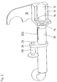
- FIG. 1 shows in the right image section the holding part 10 below a connecting pipe 30 belonging to the rear of the vehicle, to which it is firmly connected, in particular welded, by means of two connecting plates 32.
- the ball rod with shaft 20 It has an angular groove 22, one leg 22a of which begins at the end of the shaft, generally extends 3 to 4 cm coaxially, and then forms a right angle in the radially extending second leg 22b to pass over.
- the depth and width of the angular groove 22 are matched to the shape of the holding pin 14, the length of the groove to the depth of the holding part 10 and the position of the holding pin 14 located therein.
- This retaining pin 14 can be designed as a round bolt and inserted or welded into a bore leading to the opening 12. In terms of handling, it is advisable to insert the holding pin 14 into the opening from above and to fix the locking direction of the shaft 20 in a clockwise direction, so that the position of the angular groove 22 shown in the same direction in all 3 figures - also in relation to the ball head - is set.
- the shaft 20 is inserted or removed in the position shown in FIG. 2, the groove leg 22a pointing upwards. In order to produce the locking and operating position, it is then pivoted or rotated by approximately 90 ° to reach the position shown in FIG.
- the holding pin 14 which is only indicated in FIG. 1, then reaches the area of the bracing position 22c, and the connecting piece 24 lies against the front side 18 of the holding part 10.
- the locking bolt 26 should preferably be secured in its locking position (not shown).
- FIG. 2 clearly shows the position of the holding pin 14. If the ball rod is to be inserted and locked, it is now inserted from the left to the right, the retaining pin 14 sliding along the groove 22a located in the picture until the locking bolt 26 against a backdrop (not shown in the figures) welded to the front of the holding part 10 bumps, and with further movement to the right in the picture is pressed into the sleeve 28. As soon as the connecting piece 24 serving as a stop reaches the front side 18 of the holding part 10, the ball rod is rotated clockwise out of the plane of the image, with the holding pin now passing through the second groove leg 22b to the end point or to the area of the actual bracing position 22c, where the groove 22 preferably tapers conically. At this time, the locking bolt 26 guided in the bushing 28 engages in the eccentric recess 16. This is also self-adjusting, so it tends to adjust the shaft clockwise.
- the holding part 10 is shown in a cut-open form for a better overview.
Abstract
Description
Die Erfindung betrifft eine abnehmbare Anhängerkupplung, insbes. für Personenkraftwagen, mit am Fahrzeug bevorzugt verdeckt zu montierendem Halteteil für die lösbare Befestigung des Schaftes einer mit Kupplungskugel versehenen Kugelstange, wobei der Schaft eine Nut aufweist zur Aufnahme eines in der Öffnung des Halte- bzw. Aufnahmeteils befindlichen Haltestiftes und einen parallel zur Schaftachse verschiebbaren Verriegelungsbolzen, der beim Verdrehen des eingeführten Schaftes um seine Längsachse unter Federbelastung selbständig in eine außermittige Ausnehmung des Halteteils eingreift.The invention relates to a detachable trailer coupling, in particular for passenger cars, with a holding part, which is preferably concealed to be mounted on the vehicle, for the detachable fastening of the shaft of a ball rod provided with a coupling ball, the shaft having a groove for receiving a part in the opening of the holding or receiving part located retaining pin and a locking bolt which can be moved parallel to the shaft axis and which engages automatically in an eccentric recess of the holding part when the inserted shaft is rotated about its longitudinal axis under spring loading.
Eine derartige Anordnung ist aus der DE-PS 40 09 530 bekannt geworden. Auch dort erfolgt die Arretierung des Schaftes im Aufnahme- bzw. Halteteil durch ein Verdrehen. Doch haften der bekannten Anordnung mehrere Nachteile an: Zum ersten ist der Schaft bezüglich seiner mechanischen Festigkeit, insbes. seiner Biegefestigkeit, durch Längs- und Querbohrungen einschließlich Schlitz ganz erheblich geschwächt.Such an arrangement has become known from DE-PS 40 09 530. There, too, the shaft is locked in the receiving or holding part by twisting. However, there are several disadvantages to the known arrangement: firstly, the shaft is considerably weakened in terms of its mechanical strength, in particular its flexural strength, by longitudinal and transverse bores including a slot.
Zum zweiten bedeuten diese Bohrungen fertigungstechnisch einen relativ hohen Aufwand. Schließlich scheint der Verdrehwinkel von nur 30 % zu gering, um beim Auftreten größerer Kräfte im Anhängerbetrieb eine sichere Arretierung zu gewährleisten, da die Geometrie bezüglich eines ausreichenden Hintergreifens des das Halteteil quer durchsetzenden Bolzens nicht günstig gewählt ist.Secondly, these bores mean a relatively high outlay in terms of production technology. Finally, the angle of rotation of only 30% appears to be too small to ensure a secure locking when larger forces occur when towing a trailer, since the geometry is not favorably chosen with regard to sufficient engagement of the bolt which penetrates the holding part transversely.
Aus der Fig. 10 der canadischen Patentanmeldung 2 046 311 ist eine umlaufende Ringnut 6' bekanntgeworden, in die ein außermittig angeordnetes Rastglied 31' tangential nach Passieren eines ebenfalls seitlich am Schaft abgetragenen Segments 18' eingreift. Auch diese Geometrie ist unter fertigungstechnischen und mechanischen Gesichtspunkten nicht zufriedenstellend.A circumferential annular groove 6 'has become known from FIG. 10 of the Canadian patent application 2 046 311, into which an off-center locking element 31 'engages tangentially after passing a segment 18' which is also removed laterally on the shaft. This geometry is also unsatisfactory from a manufacturing and mechanical point of view.
Der Erfindung liegt daher die Aufgabe zugrunde, vorstehende Problematik zu lösen und die genannten Nachteile des Standes der Technik zu vermeiden, d.h. eine kostengünstig herstellbare Konzeption zu finden bei optimaler mechanischer Festigkeit und Sicherheit im Betriebszustand.The invention is therefore based on the object of solving the above problems and avoiding the disadvantages of the prior art, i.e. to find a cost-effective concept with optimal mechanical strength and safety in the operating state.
Die vorstehende Aufgabe wird bei einer Anhängerkupplung der eingangs genannten Art mittels der Merkmale des kennzeichnenden Teils von Patentanspruch 1 gelöst.The above object is achieved in a trailer coupling of the type mentioned by means of the features of the characterizing part of claim 1.
Erfindungswesentlich ist dabei in erster Linie die Kombination der fertigungstechnisch günstig zu realisierenden Winkelnut des Schaftes mit dem im Halte- bzw. Aufnahmeteil befindlichen feststehenden Haltestift.Essential to the invention is primarily the combination of the angular groove of the shaft, which can be produced economically in terms of production technology, with the fixed holding pin located in the holding or receiving part.
Einen weiteren kombinatorischen Vorteil liefert die Verlegung des Verriegelungsbolzen nach außerhalb des Schaftes, womit die Schwächung des Schaft-Querschnitts entfällt.Another combinatorial advantage is the relocation of the locking bolt to the outside of the shaft, which eliminates the weakening of the shaft cross-section.
Weitere vorteilhafte Ausgestaltungen sind Gegenstand der Unteransprüche. Dort sind insbes. bevorzugte geometrische Einzelmaßnahmen beschrieben, um eine sich im Betriebszustand stets selbst-nachstellende Arretierung des Schaftes zu gewährleisten Weiterhin werden optimale Abmessungen der Winkelnut angegeben.Further advantageous embodiments are the subject of the dependent claims. Preferred geometric individual measures are described there, in particular, in order to ensure that the shaft is always self-adjusting in the operating state. Furthermore, optimal dimensions of the angular groove are specified.
Im folgenden soll die Erfindung anhand einer Zeichnung näher beschrieben werden, aus der sich weitere Vorteile und Merkmale der Erfindung entnehmen lassen.The invention will be described in more detail below with reference to a drawing, from which further advantages and features of the invention can be found.
Es zeigen
- Fig. 1
- die Kugelstange und das fahrzeugseitig angebrachte Halte- bzw. Aufnahmeteil in perspektivischer Darstellung;
- Fig. 2
- die Kugelstange in Entnahme- oder Einführungsposition;
- Fig. 3
- die Kugelstange in Betriebsposition.
- Fig. 1
- the ball rod and the vehicle-side holding or receiving part in a perspective view;
- Fig. 2
- the ball rod in the removal or insertion position;
- Fig. 3
- the ball rod in the operating position.
Im einzelnen betrachtet zeigt Fig. 1 im rechten Bildausschnitt das Halteteil 10 unterhalb eines zum Fahrzeugheck gehörenden Anschlußrohres 30, mit dem es über zwei Verbindungsbleche 32 fest verbunden, insbes. verschweißt ist. Links davon sieht man die Kugelstange mit Schaft 20. Er weist eine Winkelnut 22 auf, deren einer Schenkel 22a am Schaftende beginnt, sich in der Regel 3 bis 4 cm coaxial erstreckt, um dann unter Bildung eines rechten Winkels in den radial verlaufenden zweiten Schenkel 22b überzugehen. Tiefe und Breite der Winkelnut 22 sind auf die Form des Haltestiftes 14 abgestimmt, die Länge der Nut auf die Tiefe des Halteteils 10 und die Position des darin befindlichen Haltestiftes 14.Considered in detail, FIG. 1 shows in the right image section the
Dieser Haltestift 14 kann als Rundbolzen ausgebildet und in eine zur Öffnung 12 führenden Bohrung eingesetzt bzw. eingeschweißt sein. Von der Handhabung her empfiehlt es sich, den Haltestift 14 von oben in die Öffnung zu setzen und die Verriegelungsrichtung des Schaftes 20 im Uhrzeigersinn festzulegen, womit dann auch die in allen 3 Figuren gleichsinnig gezeigte Lage der Winkelnut 22 - auch in Bezug auf den Kugelkopf - festgelegt ist.This retaining
Eingeschoben bzw. entnommen wird der Schaft 20 in der in Fig.2 gezeigten Position, wobei der Nutschenkel 22a nach oben weist. Zur Herstellung der Arretier- und Betriebsposition wird dann um ca. 90o verschwenkt bzw. verdreht, um die in Fig. 3 gezeigte Position zu erreichen.The
Dort erreicht dann der in Fig. 1 nur andeutbare Haltestift 14 den Bereich der Verspannposition 22c, und das Verbindungsstück 24 liegt an der Vorderseite 18 des Halteteils 10 an.There, the
Der Verriegelungsbolzen 26 soll bevorzugt in seiner Verriegelungsposition gesichert sein (nicht gezeichnet).The
Figur 2 zeigt die Position des Haltestiftes 14 deutlich. Soll die Kugelstange eingeschoben und arretiert werden, so wird sie nun von links nach rechts eingeschoben, wobei der Haltestift 14 entlang der im Bild oben liegenden Nut 22a gleitet bis der Verriegelungsbolzen 26 gegen eine in den Figuren nicht gezeigte an die Vorderseite des Halteteils 10 angeschweißte Kulisse stößt, und bei weiterer Bewegung nach rechts im Bild in die Büchse 28 gedrückt wird. Sobald das als Anschlag dienende Verbindungsstück 24 die Vorderseite 18 des Halteteils 10 erreicht, dreht man die Kugelstange im Uhrzeigersinn aus der Bildebene nach vorne heraus, womit nun der Haltestift den zweiten Nutschenkel 22b durchläuft bis zum Endpunkt bzw. zum Bereich der eigentlichen Verspannposition 22c, wo die Nut 22 sich bevorzugt konisch verjüngt. Zu diesem Zeitpunkt rastet der in der Büchse 28 geführte Verriegelungsbolzen 26 in die außermittige Ausnehmung 16 ein. Diese ist ebenfalls selbstnachstellend ausgebildet, tendiert also dazu, den Schaft im Uhrzeigersinn nachzustellen.Figure 2 clearly shows the position of the
In Fig. 3 ist diese Endstellung in Verriegelungsposition gezeigt. Der Kugelstangenkopf (links) ist nun ebenfalls in Betriebsposition.In Fig. 3 this end position is shown in the locked position. The ball rod head (left) is now also in the operating position.
Dabei ist, wie auch in Fig. 2, das Halteteil 10 in aufgeschnittener Form dargestellt zur besseren Übersicht.Here, as in FIG. 2, the
- 1010th
- HalteteilHolding part
- 1212th
- Öffnungopening
- 1414
- HaltestiftRetaining pin
- 1616
- Außermittige AusnehmungOff-center recess
- 1818th
- Vorderseitefront
- 2020th
- Schaft (der Kugelstange)Shaft (of the ball rod)
- 2222
- NutGroove
- 22a22a
- Erster SchenkelFirst leg
- 22b22b
- Zweiter SchenkelSecond leg
- 22c22c
- Bereich der VerspannpositionRange of the clamping position
- 2424th
- VerbindungsstückConnector
- 2626
- VerriegelungsbolzenLocking bolt
- 2828
- Büchserifle
- 3030th
- Fahrzeugheck-seitiges AnschlußrohrVehicle rear-side connection pipe
- 3232
- VerbindungsblechConnecting plate
Claims (7)
Applications Claiming Priority (2)
| Application Number | Priority Date | Filing Date | Title |
|---|---|---|---|
| DE4412513A DE4412513A1 (en) | 1994-04-12 | 1994-04-12 | Removable trailer attachment |
| DE4412513 | 1994-04-12 |
Publications (2)
| Publication Number | Publication Date |
|---|---|
| EP0677406A1 true EP0677406A1 (en) | 1995-10-18 |
| EP0677406B1 EP0677406B1 (en) | 1997-07-23 |
Family
ID=6515165
Family Applications (1)
| Application Number | Title | Priority Date | Filing Date |
|---|---|---|---|
| EP95105225A Expired - Lifetime EP0677406B1 (en) | 1994-04-12 | 1995-04-07 | Dismountable trailer coupling |
Country Status (2)
| Country | Link |
|---|---|
| EP (1) | EP0677406B1 (en) |
| DE (2) | DE4412513A1 (en) |
Cited By (1)
| Publication number | Priority date | Publication date | Assignee | Title |
|---|---|---|---|---|
| EP2042353A1 (en) | 2007-09-01 | 2009-04-01 | WESTFALIA - Automotive GmbH | Trailer coupling |
Citations (5)
| Publication number | Priority date | Publication date | Assignee | Title |
|---|---|---|---|---|
| DE863001C (en) * | 1951-05-08 | 1953-01-15 | Wilhelm Peppmeier | Drawbar for trailer couplings on vehicles |
| EP0151099A2 (en) * | 1984-01-25 | 1985-08-07 | Släpvagnskopplingar Ab | A coupling device for a vehicle |
| EP0219412A1 (en) * | 1985-10-01 | 1987-04-22 | Framatome | Device for locking a guide ring onto a plate comprising a hole and its use in a guide tube of a nuclear reactor |
| EP0332759A2 (en) * | 1987-12-24 | 1989-09-20 | NUOVA OMEC S.r.l. | Axial fixing device for connecting tubular elements |
| BE1001829A3 (en) * | 1988-06-24 | 1990-03-13 | Germain Deconinck Nv | Removable towbar combination for vehicles |
-
1994
- 1994-04-12 DE DE4412513A patent/DE4412513A1/en not_active Withdrawn
-
1995
- 1995-04-07 DE DE59500406T patent/DE59500406D1/en not_active Expired - Fee Related
- 1995-04-07 EP EP95105225A patent/EP0677406B1/en not_active Expired - Lifetime
Patent Citations (5)
| Publication number | Priority date | Publication date | Assignee | Title |
|---|---|---|---|---|
| DE863001C (en) * | 1951-05-08 | 1953-01-15 | Wilhelm Peppmeier | Drawbar for trailer couplings on vehicles |
| EP0151099A2 (en) * | 1984-01-25 | 1985-08-07 | Släpvagnskopplingar Ab | A coupling device for a vehicle |
| EP0219412A1 (en) * | 1985-10-01 | 1987-04-22 | Framatome | Device for locking a guide ring onto a plate comprising a hole and its use in a guide tube of a nuclear reactor |
| EP0332759A2 (en) * | 1987-12-24 | 1989-09-20 | NUOVA OMEC S.r.l. | Axial fixing device for connecting tubular elements |
| BE1001829A3 (en) * | 1988-06-24 | 1990-03-13 | Germain Deconinck Nv | Removable towbar combination for vehicles |
Cited By (1)
| Publication number | Priority date | Publication date | Assignee | Title |
|---|---|---|---|---|
| EP2042353A1 (en) | 2007-09-01 | 2009-04-01 | WESTFALIA - Automotive GmbH | Trailer coupling |
Also Published As
| Publication number | Publication date |
|---|---|
| DE4412513A1 (en) | 1995-10-19 |
| EP0677406B1 (en) | 1997-07-23 |
| DE59500406D1 (en) | 1997-08-28 |
Similar Documents
| Publication | Publication Date | Title |
|---|---|---|
| EP0445591A1 (en) | Device for connecting a steering column of a motor vehicle to the stub shaft of a steering gear | |
| EP3096963A1 (en) | Component attachment with a transverse force-supporting surface | |
| DE19930945C1 (en) | Fastening device for the fitting part of a fitting fixed to the seat part or seat frame | |
| DE102008061854A1 (en) | Frame joint i.e. motor vehicle frame joint, has integrated pivoting brake device, and adjusting device attached to pivoting brake half for adjusting pivoting brake half with respect to another pivoting brake half | |
| EP0677406B1 (en) | Dismountable trailer coupling | |
| DE102007060481A1 (en) | Mounting device for trailer coupling on motor vehicle, has end sided carrier strut displaceably arranged on cross bar element by bore hole and fixed in end region of cross bar element by frictional connection | |
| EP1721708A2 (en) | Assembly device for pressing in a wheel hub bearing with a pull rod | |
| EP1321317A1 (en) | Trailer hitch for motor vehicles | |
| DE202021002983U1 (en) | Self-tightening connection device for connecting at least two parts to be joined | |
| EP1803344B1 (en) | Rotary swather for a hay-making machine | |
| DE3817435C2 (en) | ||
| EP1321316B1 (en) | Trailer hitch for motor vehicles | |
| DE102017214320B4 (en) | Rear axle steering actuator for a motor vehicle | |
| EP1069020B1 (en) | Traction device for railway vehicles | |
| DE19845937C1 (en) | Fastening for bearing cap to trunnion | |
| EP1427625B1 (en) | Rotary slide valve for servo-assisted steering systems | |
| DE19515396C2 (en) | Device for quick fastening of protective tubes | |
| DE3517410A1 (en) | Apparatus for fixing detachably connectable parts | |
| DE4022764A1 (en) | REMOVABLE TRAILER ATTACHMENT | |
| DE19957640C2 (en) | connecting device | |
| AT391662B (en) | INTERMEDIATE COUPLING FOR CONNECTING VEHICLES, ESPECIALLY ROAD VEHICLES | |
| DE102018202660A1 (en) | Spoked wheel for tubeless tires | |
| DE10008297A1 (en) | Fastener for joining car components comprises bridging sleeve which fits over bolt and has tapering section which is compressed when bolt is tightened and fits against inner sleeve with indented outer surface | |
| DE102010054947A1 (en) | Device for mounting and dismounting of locking pin in test bolt of rolling bearing, has pincer-like structure, which comprises stationary lever rod and lever mechanism connected with lever rod over two flanges | |
| DE202010001710U1 (en) | Hitch for motor vehicles |
Legal Events
| Date | Code | Title | Description |
|---|---|---|---|
| PUAI | Public reference made under article 153(3) epc to a published international application that has entered the european phase |
Free format text: ORIGINAL CODE: 0009012 |
|
| AK | Designated contracting states |
Kind code of ref document: A1 Designated state(s): BE DE FR GB IT NL SE |
|
| 17P | Request for examination filed |
Effective date: 19951021 |
|
| GRAG | Despatch of communication of intention to grant |
Free format text: ORIGINAL CODE: EPIDOS AGRA |
|
| 17Q | First examination report despatched |
Effective date: 19961106 |
|
| GRAH | Despatch of communication of intention to grant a patent |
Free format text: ORIGINAL CODE: EPIDOS IGRA |
|
| GRAH | Despatch of communication of intention to grant a patent |
Free format text: ORIGINAL CODE: EPIDOS IGRA |
|
| GRAA | (expected) grant |
Free format text: ORIGINAL CODE: 0009210 |
|
| AK | Designated contracting states |
Kind code of ref document: B1 Designated state(s): BE DE FR GB IT NL SE |
|
| PG25 | Lapsed in a contracting state [announced via postgrant information from national office to epo] |
Ref country code: NL Free format text: LAPSE BECAUSE OF FAILURE TO SUBMIT A TRANSLATION OF THE DESCRIPTION OR TO PAY THE FEE WITHIN THE PRESCRIBED TIME-LIMIT Effective date: 19970723 Ref country code: IT Free format text: LAPSE BECAUSE OF FAILURE TO SUBMIT A TRANSLATION OF THE DESCRIPTION OR TO PAY THE FEE WITHIN THE PRE;WARNING: LAPSES OF ITALIAN PATENTS WITH EFFECTIVE DATE BEFORE 2007 MAY HAVE OCCURRED AT ANY TIME BEFORE 2007. THE CORRECT EFFECTIVE DATE MAY BE DIFFERENT FROM THE ONE RECORDED.SCRIBED TIME-LIMIT Effective date: 19970723 |
|
| REF | Corresponds to: |
Ref document number: 59500406 Country of ref document: DE Date of ref document: 19970828 |
|
| GBT | Gb: translation of ep patent filed (gb section 77(6)(a)/1977) |
Effective date: 19970912 |
|
| PG25 | Lapsed in a contracting state [announced via postgrant information from national office to epo] |
Ref country code: SE Effective date: 19971023 |
|
| ET | Fr: translation filed | ||
| NLV1 | Nl: lapsed or annulled due to failure to fulfill the requirements of art. 29p and 29m of the patents act | ||
| PGFP | Annual fee paid to national office [announced via postgrant information from national office to epo] |
Ref country code: BE Payment date: 19980422 Year of fee payment: 4 |
|
| PLBE | No opposition filed within time limit |
Free format text: ORIGINAL CODE: 0009261 |
|
| STAA | Information on the status of an ep patent application or granted ep patent |
Free format text: STATUS: NO OPPOSITION FILED WITHIN TIME LIMIT |
|
| 26N | No opposition filed | ||
| PG25 | Lapsed in a contracting state [announced via postgrant information from national office to epo] |
Ref country code: BE Free format text: LAPSE BECAUSE OF NON-PAYMENT OF DUE FEES Effective date: 19990430 |
|
| BERE | Be: lapsed |
Owner name: PEKA-FAHRZEUGBAU G.M.B.H. & CO. K.G. Effective date: 19990430 |
|
| PGFP | Annual fee paid to national office [announced via postgrant information from national office to epo] |
Ref country code: FR Payment date: 20010417 Year of fee payment: 7 |
|
| PGFP | Annual fee paid to national office [announced via postgrant information from national office to epo] |
Ref country code: GB Payment date: 20010423 Year of fee payment: 7 |
|
| PGFP | Annual fee paid to national office [announced via postgrant information from national office to epo] |
Ref country code: DE Payment date: 20010627 Year of fee payment: 7 |
|
| REG | Reference to a national code |
Ref country code: GB Ref legal event code: IF02 |
|
| PG25 | Lapsed in a contracting state [announced via postgrant information from national office to epo] |
Ref country code: GB Free format text: LAPSE BECAUSE OF NON-PAYMENT OF DUE FEES Effective date: 20020407 |
|
| PG25 | Lapsed in a contracting state [announced via postgrant information from national office to epo] |
Ref country code: DE Free format text: LAPSE BECAUSE OF NON-PAYMENT OF DUE FEES Effective date: 20021101 |
|
| GBPC | Gb: european patent ceased through non-payment of renewal fee |
Effective date: 20020407 |
|
| PG25 | Lapsed in a contracting state [announced via postgrant information from national office to epo] |
Ref country code: FR Free format text: LAPSE BECAUSE OF NON-PAYMENT OF DUE FEES Effective date: 20021231 |
|
| REG | Reference to a national code |
Ref country code: FR Ref legal event code: ST |