EP0677406A1 - Attelage de remorque détachable - Google Patents
Attelage de remorque détachable Download PDFInfo
- Publication number
- EP0677406A1 EP0677406A1 EP95105225A EP95105225A EP0677406A1 EP 0677406 A1 EP0677406 A1 EP 0677406A1 EP 95105225 A EP95105225 A EP 95105225A EP 95105225 A EP95105225 A EP 95105225A EP 0677406 A1 EP0677406 A1 EP 0677406A1
- Authority
- EP
- European Patent Office
- Prior art keywords
- shaft
- locking bolt
- trailer coupling
- leg
- groove
- Prior art date
- Legal status (The legal status is an assumption and is not a legal conclusion. Google has not performed a legal analysis and makes no representation as to the accuracy of the status listed.)
- Granted
Links
Images


Classifications
-
- B—PERFORMING OPERATIONS; TRANSPORTING
- B60—VEHICLES IN GENERAL
- B60D—VEHICLE CONNECTIONS
- B60D1/00—Traction couplings; Hitches; Draw-gear; Towing devices
- B60D1/48—Traction couplings; Hitches; Draw-gear; Towing devices characterised by the mounting
- B60D1/52—Traction couplings; Hitches; Draw-gear; Towing devices characterised by the mounting removably mounted
Definitions
- the invention relates to a detachable trailer coupling, in particular for passenger cars, with a holding part, which is preferably concealed to be mounted on the vehicle, for the detachable fastening of the shaft of a ball rod provided with a coupling ball, the shaft having a groove for receiving a part in the opening of the holding or receiving part located retaining pin and a locking bolt which can be moved parallel to the shaft axis and which engages automatically in an eccentric recess of the holding part when the inserted shaft is rotated about its longitudinal axis under spring loading.
- a circumferential annular groove 6 ' has become known from FIG. 10 of the Canadian patent application 2 046 311, into which an off-center locking element 31 'engages tangentially after passing a segment 18' which is also removed laterally on the shaft.
- This geometry is also unsatisfactory from a manufacturing and mechanical point of view.
- the invention is therefore based on the object of solving the above problems and avoiding the disadvantages of the prior art, i.e. to find a cost-effective concept with optimal mechanical strength and safety in the operating state.
- Essential to the invention is primarily the combination of the angular groove of the shaft, which can be produced economically in terms of production technology, with the fixed holding pin located in the holding or receiving part.
- Another combinatorial advantage is the relocation of the locking bolt to the outside of the shaft, which eliminates the weakening of the shaft cross-section.
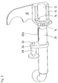
- FIG. 1 shows in the right image section the holding part 10 below a connecting pipe 30 belonging to the rear of the vehicle, to which it is firmly connected, in particular welded, by means of two connecting plates 32.
- the ball rod with shaft 20 It has an angular groove 22, one leg 22a of which begins at the end of the shaft, generally extends 3 to 4 cm coaxially, and then forms a right angle in the radially extending second leg 22b to pass over.
- the depth and width of the angular groove 22 are matched to the shape of the holding pin 14, the length of the groove to the depth of the holding part 10 and the position of the holding pin 14 located therein.
- This retaining pin 14 can be designed as a round bolt and inserted or welded into a bore leading to the opening 12. In terms of handling, it is advisable to insert the holding pin 14 into the opening from above and to fix the locking direction of the shaft 20 in a clockwise direction, so that the position of the angular groove 22 shown in the same direction in all 3 figures - also in relation to the ball head - is set.
- the shaft 20 is inserted or removed in the position shown in FIG. 2, the groove leg 22a pointing upwards. In order to produce the locking and operating position, it is then pivoted or rotated by approximately 90 ° to reach the position shown in FIG.
- the holding pin 14 which is only indicated in FIG. 1, then reaches the area of the bracing position 22c, and the connecting piece 24 lies against the front side 18 of the holding part 10.
- the locking bolt 26 should preferably be secured in its locking position (not shown).
- FIG. 2 clearly shows the position of the holding pin 14. If the ball rod is to be inserted and locked, it is now inserted from the left to the right, the retaining pin 14 sliding along the groove 22a located in the picture until the locking bolt 26 against a backdrop (not shown in the figures) welded to the front of the holding part 10 bumps, and with further movement to the right in the picture is pressed into the sleeve 28. As soon as the connecting piece 24 serving as a stop reaches the front side 18 of the holding part 10, the ball rod is rotated clockwise out of the plane of the image, with the holding pin now passing through the second groove leg 22b to the end point or to the area of the actual bracing position 22c, where the groove 22 preferably tapers conically. At this time, the locking bolt 26 guided in the bushing 28 engages in the eccentric recess 16. This is also self-adjusting, so it tends to adjust the shaft clockwise.
- the holding part 10 is shown in a cut-open form for a better overview.
Landscapes
- Engineering & Computer Science (AREA)
- Transportation (AREA)
- Mechanical Engineering (AREA)
- Pivots And Pivotal Connections (AREA)
- Snaps, Bayonet Connections, Set Pins, And Snap Rings (AREA)
Applications Claiming Priority (2)
| Application Number | Priority Date | Filing Date | Title |
|---|---|---|---|
| DE4412513A DE4412513A1 (de) | 1994-04-12 | 1994-04-12 | Abnehmbare Anhängerkupplung |
| DE4412513 | 1994-04-12 |
Publications (2)
| Publication Number | Publication Date |
|---|---|
| EP0677406A1 true EP0677406A1 (fr) | 1995-10-18 |
| EP0677406B1 EP0677406B1 (fr) | 1997-07-23 |
Family
ID=6515165
Family Applications (1)
| Application Number | Title | Priority Date | Filing Date |
|---|---|---|---|
| EP95105225A Expired - Lifetime EP0677406B1 (fr) | 1994-04-12 | 1995-04-07 | Attelage de remorque détachable |
Country Status (2)
| Country | Link |
|---|---|
| EP (1) | EP0677406B1 (fr) |
| DE (2) | DE4412513A1 (fr) |
Cited By (1)
| Publication number | Priority date | Publication date | Assignee | Title |
|---|---|---|---|---|
| EP2042353A1 (fr) | 2007-09-01 | 2009-04-01 | WESTFALIA - Automotive GmbH | Attelage de remorque |
Citations (5)
| Publication number | Priority date | Publication date | Assignee | Title |
|---|---|---|---|---|
| DE863001C (de) * | 1951-05-08 | 1953-01-15 | Wilhelm Peppmeier | Zugstange fuer Anhaengerkupplungen an Fahrzeugen |
| EP0151099A2 (fr) * | 1984-01-25 | 1985-08-07 | Släpvagnskopplingar Ab | Dispositif d'accouplement pour un véhicule |
| EP0219412A1 (fr) * | 1985-10-01 | 1987-04-22 | Framatome | Dispositif de verrouillage d'une bague de guidage sur une plaque comportant une ouverture et son application à un tube guide de réacteur nucléaire |
| EP0332759A2 (fr) * | 1987-12-24 | 1989-09-20 | NUOVA OMEC S.r.l. | Dispositif de fixation axiale pour la connexion d'éléments tubulaires |
| BE1001829A3 (nl) * | 1988-06-24 | 1990-03-13 | Germain Deconinck Nv | Uitneembare trekstuk combinatie voor voertuigen. |
-
1994
- 1994-04-12 DE DE4412513A patent/DE4412513A1/de not_active Withdrawn
-
1995
- 1995-04-07 EP EP95105225A patent/EP0677406B1/fr not_active Expired - Lifetime
- 1995-04-07 DE DE59500406T patent/DE59500406D1/de not_active Expired - Fee Related
Patent Citations (5)
| Publication number | Priority date | Publication date | Assignee | Title |
|---|---|---|---|---|
| DE863001C (de) * | 1951-05-08 | 1953-01-15 | Wilhelm Peppmeier | Zugstange fuer Anhaengerkupplungen an Fahrzeugen |
| EP0151099A2 (fr) * | 1984-01-25 | 1985-08-07 | Släpvagnskopplingar Ab | Dispositif d'accouplement pour un véhicule |
| EP0219412A1 (fr) * | 1985-10-01 | 1987-04-22 | Framatome | Dispositif de verrouillage d'une bague de guidage sur une plaque comportant une ouverture et son application à un tube guide de réacteur nucléaire |
| EP0332759A2 (fr) * | 1987-12-24 | 1989-09-20 | NUOVA OMEC S.r.l. | Dispositif de fixation axiale pour la connexion d'éléments tubulaires |
| BE1001829A3 (nl) * | 1988-06-24 | 1990-03-13 | Germain Deconinck Nv | Uitneembare trekstuk combinatie voor voertuigen. |
Cited By (1)
| Publication number | Priority date | Publication date | Assignee | Title |
|---|---|---|---|---|
| EP2042353A1 (fr) | 2007-09-01 | 2009-04-01 | WESTFALIA - Automotive GmbH | Attelage de remorque |
Also Published As
| Publication number | Publication date |
|---|---|
| DE59500406D1 (de) | 1997-08-28 |
| DE4412513A1 (de) | 1995-10-19 |
| EP0677406B1 (fr) | 1997-07-23 |
Similar Documents
| Publication | Publication Date | Title |
|---|---|---|
| EP3096963B1 (fr) | Attache de composant avec surface de support supportant les forces transversales | |
| DE102008061854A1 (de) | Scharnier | |
| EP0677406B1 (fr) | Attelage de remorque détachable | |
| DE102007060481A1 (de) | Befestigungsvorrichtung für eine Anhängerkupplung an Kraftfahrzeugen | |
| EP1721708A2 (fr) | Dispositif pour l'assemblage d'un palier de roue avec une tige de traction | |
| EP1321317A1 (fr) | Dispositif d'attelage pour véhicules automobiles | |
| DE202021002983U1 (de) | Selbstspannende Verbindungsvorrichtung zum Verbinden von mindestens zwei Fügeteilen | |
| EP1803344B1 (fr) | Andaineur pour une faneuse | |
| DE3817435C2 (fr) | ||
| EP1321316B1 (fr) | Dispositif d'attelage pour véhicules automobiles | |
| DE102017214320B4 (de) | Aktuator einer Hinterachslenkung für ein Kraftfahrzeug | |
| EP1069020B1 (fr) | Dispositif de traction pour véhicules ferroviaires | |
| DE19845937C1 (de) | Vorrichtung zum Verbinden von mindestens zwei Bauteilen mit einem dritten Bauteil, insbesondere von einem geteilten Halter mit einem Lagerbock | |
| EP1427625B1 (fr) | Soupape a tiroir rotatif pour systemes de direction assistee | |
| DE19515396C2 (de) | Vorrichtung zum Schnellbefestigen von Schutzschläuchen | |
| DE3517410A1 (de) | Vorrichtung zum festlegen loesbar verbindbarer teile | |
| DE4022764A1 (de) | Abnehmbare anhaengerkupplung | |
| DE19957640C2 (de) | Verbindungsvorrichtung | |
| AT391662B (de) | Zwischenkupplung zum verbinden von fahrzeugen, insbesondere von strassenfahrzeugen | |
| DE102018202660A1 (de) | Speichenrad für schlauchlose Reifen | |
| DE10008297A1 (de) | Spannvorrichtung für in Spannrichtung zueinander beabstandete Teile | |
| DE102010054947A1 (de) | Vorrichtung zum Montieren und Demontieren eines Sicherungsstifts in Prüfbolzen von Wälzlagern | |
| DE202010001710U1 (de) | Anhängevorrichtung für Kraftfahrzeuge | |
| CH680721A5 (en) | Vehicle towing hitch - comprises bar with hinging hook locked in working position by pulling on bar | |
| DE3334250A1 (de) | Anordnung zur herstellung eines loesbaren festsitzes einer lagerbuchse an steifen wandteilen |
Legal Events
| Date | Code | Title | Description |
|---|---|---|---|
| PUAI | Public reference made under article 153(3) epc to a published international application that has entered the european phase |
Free format text: ORIGINAL CODE: 0009012 |
|
| AK | Designated contracting states |
Kind code of ref document: A1 Designated state(s): BE DE FR GB IT NL SE |
|
| 17P | Request for examination filed |
Effective date: 19951021 |
|
| GRAG | Despatch of communication of intention to grant |
Free format text: ORIGINAL CODE: EPIDOS AGRA |
|
| 17Q | First examination report despatched |
Effective date: 19961106 |
|
| GRAH | Despatch of communication of intention to grant a patent |
Free format text: ORIGINAL CODE: EPIDOS IGRA |
|
| GRAH | Despatch of communication of intention to grant a patent |
Free format text: ORIGINAL CODE: EPIDOS IGRA |
|
| GRAA | (expected) grant |
Free format text: ORIGINAL CODE: 0009210 |
|
| AK | Designated contracting states |
Kind code of ref document: B1 Designated state(s): BE DE FR GB IT NL SE |
|
| PG25 | Lapsed in a contracting state [announced via postgrant information from national office to epo] |
Ref country code: NL Free format text: LAPSE BECAUSE OF FAILURE TO SUBMIT A TRANSLATION OF THE DESCRIPTION OR TO PAY THE FEE WITHIN THE PRESCRIBED TIME-LIMIT Effective date: 19970723 Ref country code: IT Free format text: LAPSE BECAUSE OF FAILURE TO SUBMIT A TRANSLATION OF THE DESCRIPTION OR TO PAY THE FEE WITHIN THE PRE;WARNING: LAPSES OF ITALIAN PATENTS WITH EFFECTIVE DATE BEFORE 2007 MAY HAVE OCCURRED AT ANY TIME BEFORE 2007. THE CORRECT EFFECTIVE DATE MAY BE DIFFERENT FROM THE ONE RECORDED.SCRIBED TIME-LIMIT Effective date: 19970723 |
|
| REF | Corresponds to: |
Ref document number: 59500406 Country of ref document: DE Date of ref document: 19970828 |
|
| GBT | Gb: translation of ep patent filed (gb section 77(6)(a)/1977) |
Effective date: 19970912 |
|
| PG25 | Lapsed in a contracting state [announced via postgrant information from national office to epo] |
Ref country code: SE Effective date: 19971023 |
|
| ET | Fr: translation filed | ||
| NLV1 | Nl: lapsed or annulled due to failure to fulfill the requirements of art. 29p and 29m of the patents act | ||
| PGFP | Annual fee paid to national office [announced via postgrant information from national office to epo] |
Ref country code: BE Payment date: 19980422 Year of fee payment: 4 |
|
| PLBE | No opposition filed within time limit |
Free format text: ORIGINAL CODE: 0009261 |
|
| STAA | Information on the status of an ep patent application or granted ep patent |
Free format text: STATUS: NO OPPOSITION FILED WITHIN TIME LIMIT |
|
| 26N | No opposition filed | ||
| PG25 | Lapsed in a contracting state [announced via postgrant information from national office to epo] |
Ref country code: BE Free format text: LAPSE BECAUSE OF NON-PAYMENT OF DUE FEES Effective date: 19990430 |
|
| BERE | Be: lapsed |
Owner name: PEKA-FAHRZEUGBAU G.M.B.H. & CO. K.G. Effective date: 19990430 |
|
| PGFP | Annual fee paid to national office [announced via postgrant information from national office to epo] |
Ref country code: FR Payment date: 20010417 Year of fee payment: 7 |
|
| PGFP | Annual fee paid to national office [announced via postgrant information from national office to epo] |
Ref country code: GB Payment date: 20010423 Year of fee payment: 7 |
|
| PGFP | Annual fee paid to national office [announced via postgrant information from national office to epo] |
Ref country code: DE Payment date: 20010627 Year of fee payment: 7 |
|
| REG | Reference to a national code |
Ref country code: GB Ref legal event code: IF02 |
|
| PG25 | Lapsed in a contracting state [announced via postgrant information from national office to epo] |
Ref country code: GB Free format text: LAPSE BECAUSE OF NON-PAYMENT OF DUE FEES Effective date: 20020407 |
|
| PG25 | Lapsed in a contracting state [announced via postgrant information from national office to epo] |
Ref country code: DE Free format text: LAPSE BECAUSE OF NON-PAYMENT OF DUE FEES Effective date: 20021101 |
|
| GBPC | Gb: european patent ceased through non-payment of renewal fee |
Effective date: 20020407 |
|
| PG25 | Lapsed in a contracting state [announced via postgrant information from national office to epo] |
Ref country code: FR Free format text: LAPSE BECAUSE OF NON-PAYMENT OF DUE FEES Effective date: 20021231 |
|
| REG | Reference to a national code |
Ref country code: FR Ref legal event code: ST |