EP0332759A2 - Dispositif de fixation axiale pour la connexion d'éléments tubulaires - Google Patents
Dispositif de fixation axiale pour la connexion d'éléments tubulaires Download PDFInfo
- Publication number
- EP0332759A2 EP0332759A2 EP88121481A EP88121481A EP0332759A2 EP 0332759 A2 EP0332759 A2 EP 0332759A2 EP 88121481 A EP88121481 A EP 88121481A EP 88121481 A EP88121481 A EP 88121481A EP 0332759 A2 EP0332759 A2 EP 0332759A2
- Authority
- EP
- European Patent Office
- Prior art keywords
- projection
- section
- groove
- pipe
- receiving end
- Prior art date
- Legal status (The legal status is an assumption and is not a legal conclusion. Google has not performed a legal analysis and makes no representation as to the accuracy of the status listed.)
- Withdrawn
Links
- 230000008878 coupling Effects 0.000 claims description 23
- 238000010168 coupling process Methods 0.000 claims description 23
- 238000005859 coupling reaction Methods 0.000 claims description 23
- 230000007423 decrease Effects 0.000 claims description 6
- 244000007853 Sarothamnus scoparius Species 0.000 claims description 5
- 238000004140 cleaning Methods 0.000 claims description 4
- 239000000463 material Substances 0.000 description 5
- 239000002184 metal Substances 0.000 description 3
- 238000010276 construction Methods 0.000 description 2
- 238000007373 indentation Methods 0.000 description 2
- 238000004519 manufacturing process Methods 0.000 description 2
- 230000002411 adverse Effects 0.000 description 1
- 238000005452 bending Methods 0.000 description 1
- 239000002131 composite material Substances 0.000 description 1
- 238000005520 cutting process Methods 0.000 description 1
- 230000000694 effects Effects 0.000 description 1
- 238000005516 engineering process Methods 0.000 description 1
- 238000003780 insertion Methods 0.000 description 1
- 230000037431 insertion Effects 0.000 description 1
- 230000014759 maintenance of location Effects 0.000 description 1
- 238000000034 method Methods 0.000 description 1
- 238000004806 packaging method and process Methods 0.000 description 1
- 238000003672 processing method Methods 0.000 description 1
- 230000002035 prolonged effect Effects 0.000 description 1
- 238000005096 rolling process Methods 0.000 description 1
- 238000003860 storage Methods 0.000 description 1
Images
Classifications
-
- F—MECHANICAL ENGINEERING; LIGHTING; HEATING; WEAPONS; BLASTING
- F16—ENGINEERING ELEMENTS AND UNITS; GENERAL MEASURES FOR PRODUCING AND MAINTAINING EFFECTIVE FUNCTIONING OF MACHINES OR INSTALLATIONS; THERMAL INSULATION IN GENERAL
- F16B—DEVICES FOR FASTENING OR SECURING CONSTRUCTIONAL ELEMENTS OR MACHINE PARTS TOGETHER, e.g. NAILS, BOLTS, CIRCLIPS, CLAMPS, CLIPS OR WEDGES; JOINTS OR JOINTING
- F16B7/00—Connections of rods or tubes, e.g. of non-circular section, mutually, including resilient connections
- F16B7/20—Connections of rods or tubes, e.g. of non-circular section, mutually, including resilient connections using bayonet connections
-
- B—PERFORMING OPERATIONS; TRANSPORTING
- B25—HAND TOOLS; PORTABLE POWER-DRIVEN TOOLS; MANIPULATORS
- B25G—HANDLES FOR HAND IMPLEMENTS
- B25G3/00—Attaching handles to the implements
- B25G3/02—Socket, tang, or like fixings
- B25G3/12—Locking and securing devices
- B25G3/16—Locking and securing devices comprising bayonet joints
-
- Y—GENERAL TAGGING OF NEW TECHNOLOGICAL DEVELOPMENTS; GENERAL TAGGING OF CROSS-SECTIONAL TECHNOLOGIES SPANNING OVER SEVERAL SECTIONS OF THE IPC; TECHNICAL SUBJECTS COVERED BY FORMER USPC CROSS-REFERENCE ART COLLECTIONS [XRACs] AND DIGESTS
- Y10—TECHNICAL SUBJECTS COVERED BY FORMER USPC
- Y10T—TECHNICAL SUBJECTS COVERED BY FORMER US CLASSIFICATION
- Y10T403/00—Joints and connections
- Y10T403/70—Interfitted members
- Y10T403/7005—Lugged member, rotary engagement
- Y10T403/7007—Bayonet joint
Definitions
- the invention relates to a device for axial, transversely rigid fastening in bayonet couplings, in particular for the connection of pipe pieces of broom handles or handles of similar cleaning devices
- tube made of light metal is used as the material, which is generally coated with plastic.
- Metal handles of this type are increasingly composed of a plurality of pieces of pipe in order to be able to change the length and adapt to the respective purpose of use and / or to facilitate packaging, storage and transport.
- bayonet couplings are generally provided, in which a tapered end (pin end) engages in a receiving end of the other pipe section.
- Each pipe section has a tapered spigot end and a receptacle end that is not set back in diameter, so that the pipe sections interlock can be used to produce the desired length.
- the tapered spigot end has a thread which is pressed directly into the material of the pipe section made of sheet metal by rolling and which can be screwed into a corresponding internal thread which is machined in the same way into the receiving end of the other pipe section.
- the pin end of the one piece of pipe has a bore in which a pin is radially adjustable, which pin can be pressed into the pin end against the force of a spring.
- the invention is therefore based on the object of providing a device for axially securing bayonet couplings in the field of application explained above, which at the same time allows a good determination in the circumferential direction without play, without the production costs being adversely affected thereby.
- Another object is to design this device in such a way that it cannot be released unintentionally.
- this object is achieved according to the invention in that the receiving end of a pipe piece has at least one inwardly projecting projection, which has a groove in the
- the end of the other pipe piece is assigned, which consists of a first, axial section and an adjoining second, inclined section is composed, which has the same inclination as the projection and the groove depth decreases towards the groove end.
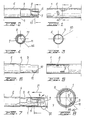
- Figures 1 and 2 show a receiving end 1 of a pipe section with a bayonet coupling and a coaxially opposite end section 2 of another pipe section with a tapered pin end 3 for the bayonet coupling, which can be inserted into the receiving end 1 and then abuts against the end with a circumferential shoulder 4 .
- an indentation 5 is stamped in deep-drawing technology, which has a rectangular shape, the two larger sides being inclined transversely to the coupling axis. This indentation 5 corresponds in the interior of the receiving end 1 (see FIGS. 3 and 5) to a projection 5 which of course has the same arrangement.
- a groove 6 is pressed into the pin end 3 of the other pipe section 2, preferably also in the manner of the deep-drawing technique.
- the groove 6 has a first section 7 which extends in the axial direction with respect to the coupling and the depth and width of which are dimensioned such that it can accommodate the front face of the projection 5 in the manner explained below.
- a second section 8 follows in the groove 6, which has the same oblique course in the transverse direction as the projection 5 and whose width is so large that it can accommodate the projection 5 on its smaller side.
- the depth of the inclined section 8 is initially as great as that of the axial section 7, but gradually decreases, which will also be discussed further below.
- an elongated hole 9 is machined into the receiving end 1, which extends in the longitudinal direction and is cut into the material of the pipe section.
- the slot 9 is shown in dashed lines, since it is covered here and lies on the back, as shown in Figures 3 and 5, from which it follows that the slot 9 is approximately opposite the projection 5 radially.
- an incision segment 10 running in the longitudinal direction is worked into the pin end 3, the front edge of which is notched clockwise in the direction of rotation of the receiving end 1 (arrow f2 in FIG. 7) and is curved outwards with respect to the tube piece, whereby a projection 11 is formed.
- the other edge of the incision segment 10, however, is notched inwards, which is shown in FIG. 4 and will be explained later.
- the device according to the invention works in the following way:
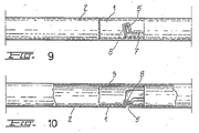
- the receiving end 1 and the pin end 3 of the bayonet coupling according to the invention are arranged coaxially opposite one another in such a way that, according to FIGS. 1 and 2, the inwardly projecting projection 5 of the receiving end 1 is opposite the insertion end of the groove 6 which is worked into the pin end 3. Then the two pipe sections 1 and 3 are assembled in the direction of arrow f1 in FIG. 7, for which purpose the pin end 3 is inserted into the receiving end 1 such that the projection 5 engages in the axial section 7 of the groove 6.
- the receiving end 1 When the projection 5 has reached the end of the axial section 7 of the groove, the receiving end 1 is rotated in the direction of arrow f2 in FIG. 7 clockwise by about a quarter turn. In this way, the projection 5 engages in the inclined section 8 of the groove 6, which has the same inclination as the projection 5 (see FIG. 9). With this screwing movement, the coupling is fixed axially.
- the projection 5 Since the depth of the inclined section 8 of the groove 6 decreases towards the end, the projection 5 is gradually clamped until it is blocked in the section 8 (see FIG. 10), as a result of which the coupling becomes very stiff and no radial play or no play allows in the circumferential direction.
- This property of the particularly good Rigidity does not decrease even after a more or less long period of use, which is the case in the prior art, because the projection 5 always remains clamped in the groove section 8, since its depth decreases towards the groove end without the edge of the receiving end 1 being forceful - Or is pressed positively against the annular shoulder 4 of the pin end 3 or must run onto this.
- the receiving end 1 of the bayonet coupling can have several devices according to the invention, for example two or even more projections 5, which cooperate with two or correspondingly more grooves 6 on the pin end 3.
- the projection 11 on the pin end 3 also enters the receiving end 1, whereby it is first elastically compressed by this due to the elasticity of the incision segment 10 (cf. FIG. 7).
- the device according to the invention is thus a robust coupling for the cases mentioned, so that the pipe pieces, for example for broomsticks, are axially firmly connected to one another, an excellent connection without play being secured in the circumferential direction after prolonged use, which prevents unintentional loosening . Since no additional equipment or materials are required, production can be carried out at low cost because it is based on the simple processing methods such as stamping, deep drawing, cutting and bending.
Applications Claiming Priority (4)
| Application Number | Priority Date | Filing Date | Title |
|---|---|---|---|
| IT502287U IT212265Z2 (it) | 1987-12-24 | 1987-12-24 | Dispositivo economico di ritegno assiale trasversalmente rigido negli innesti a baionetta per unire spezzoni di tubo a costituire manici per scope o simili attrezzi da pulizia |
| IT5022U | 1987-12-24 | ||
| IT4714U | 1988-01-26 | ||
| IT471488U IT217873Z2 (it) | 1988-01-27 | 1988-01-27 | Fermo di sicurezza autobloccante, particolarmente per dispositivi di ritegno assiale negli innesti a baionetta destinati ad unire spezzoni di tubo a costituire manici per scope o simili attrezzi da pulizia |
Publications (2)
| Publication Number | Publication Date |
|---|---|
| EP0332759A2 true EP0332759A2 (fr) | 1989-09-20 |
| EP0332759A3 EP0332759A3 (fr) | 1992-02-26 |
Family
ID=26325572
Family Applications (1)
| Application Number | Title | Priority Date | Filing Date |
|---|---|---|---|
| EP19880121481 Withdrawn EP0332759A3 (fr) | 1987-12-24 | 1988-12-22 | Dispositif de fixation axiale pour la connexion d'éléments tubulaires |
Country Status (2)
| Country | Link |
|---|---|
| US (1) | US4911573A (fr) |
| EP (1) | EP0332759A3 (fr) |
Cited By (5)
| Publication number | Priority date | Publication date | Assignee | Title |
|---|---|---|---|---|
| EP0677406A1 (fr) * | 1994-04-12 | 1995-10-18 | PEKA-Fahrzeugbau GmbH & Co. KG | Attelage de remorque détachable |
| EP0730841A1 (fr) * | 1995-03-07 | 1996-09-11 | Siemens Aktiengesellschaft | Corps d'aspirateur |
| DE19527953A1 (de) * | 1995-08-01 | 1997-02-06 | Ralf Niemeier | Vorrichtung zur Befestigung von Beschlägen auf Hohlkammerprofilen |
| DE10246773B3 (de) * | 2002-10-07 | 2004-04-15 | Philipp Waldinger | Decken und Wandbefestigung mit Befestigungsstange für Handel und Dienstleistungseinrichtungen sowie Fahrzeug- und Innenausbau |
| DE10344796B3 (de) * | 2002-10-07 | 2005-06-23 | Philipp Waldinger | Decken- und Wandbefestigung mit Befestigungsstange (Befestigungsrohr) für Handel und Dienstleistungseinrichtungen, sowie Fahrzeugbau und Innenausbau |
Families Citing this family (26)
| Publication number | Priority date | Publication date | Assignee | Title |
|---|---|---|---|---|
| US5272894A (en) * | 1989-03-22 | 1993-12-28 | Star Lock Systems, Inc. | Fractional-rotation latching system with retrofit capability |
| US5197314A (en) * | 1989-03-22 | 1993-03-30 | Star Lock Systems, Inc. | Door latch with lock and release for vending machines and the like |
| US5467619A (en) * | 1989-03-22 | 1995-11-21 | Star Lock Systems, Inc. | Post latching systems |
| US5141355A (en) * | 1989-03-22 | 1992-08-25 | Star Lock Systems, Inc. | Lock and release apparatus |
| US5269161A (en) * | 1989-09-06 | 1993-12-14 | Star Lock Systems, Inc. | Latching system |
| US5651732A (en) * | 1996-04-02 | 1997-07-29 | Security Chimneys International Inc. | Leak-proof venting system |
| US7766022B2 (en) * | 2005-06-16 | 2010-08-03 | Eurio, Inc. | Modular system for concealment and shelter |
| US6811190B1 (en) * | 2001-08-09 | 2004-11-02 | Metal-Fab, Inc. | Tab-lock fastener for interlocking vent pipe |
| CN1299041C (zh) * | 2001-11-28 | 2007-02-07 | 弗利亚特克公司 | 插式接合器 |
| DE10159669A1 (de) * | 2001-12-05 | 2003-07-03 | Rolls Royce Deutschland | Bajonettverbindung für ein Ringgehäuse eines Hochdruckkompressors einer Gasturbine |
| US6854919B2 (en) | 2002-06-20 | 2005-02-15 | S.C. Johnson & Son, Inc. | Push-lock handle assembly |
| US6925686B2 (en) * | 2002-06-20 | 2005-08-09 | S.C. Johnson & Son, Inc. | Twist-lock handle assembly |
| US8210577B2 (en) * | 2003-08-22 | 2012-07-03 | Echo, Incorporated | Connecting system for telescopingly engaged elements and method of maintaining the elements together using the system |
| CA2552496A1 (fr) * | 2005-07-19 | 2007-01-19 | Cfm U.S. Corporation | Dispositif de verrouillage d'event |
| GB2432183A (en) * | 2005-11-10 | 2007-05-16 | Camlock Systems Ltd | Quick-release/secure lock converter and lock for a vending or gaming machine or the like |
| US7624603B2 (en) * | 2005-11-10 | 2009-12-01 | Trevor Perks | Quick release lock |
| JP4673755B2 (ja) * | 2006-01-17 | 2011-04-20 | 本田技研工業株式会社 | 自動二、三輪車 |
| US20090090513A1 (en) * | 2006-08-22 | 2009-04-09 | Harold Steven Bissonnette | System and Method for Conveying a Wired Coiled Assembly |
| US7861776B2 (en) * | 2006-08-22 | 2011-01-04 | Schlumberger Technology Corporation | System and method for forming a coiled tubing connection |
| GB2503057B (en) * | 2012-12-11 | 2014-05-07 | William Edward Horsley | Multi section pole |
| DE102013106496B3 (de) * | 2013-06-21 | 2014-11-06 | Leifheit Ag | Segmentierter Gerätestiel mit Stielrohrverbindung |
| CN203873003U (zh) * | 2014-04-16 | 2014-10-15 | 林光榕 | 电子烟 |
| US20150376912A1 (en) * | 2014-06-28 | 2015-12-31 | Evrio, Inc. | Modular System Including Shaft Segments Having Configuration and Breakdown Attachments |
| US10091948B2 (en) * | 2014-07-02 | 2018-10-09 | Wicked Tuff Gear, Llc | Light pole saw |
| US10945381B1 (en) * | 2014-07-02 | 2021-03-16 | Outdoor Product Innovations, Inc. | Modular tools with detachable coupling |
| JP6652803B2 (ja) * | 2015-09-25 | 2020-02-26 | 日本製鉄株式会社 | 管材の接続構造及び管材の接続方法 |
Citations (3)
| Publication number | Priority date | Publication date | Assignee | Title |
|---|---|---|---|---|
| GB569693A (en) * | 1943-09-01 | 1945-06-05 | Dorothy Emma Underwood | Improvements in and relating to brooms and brushes |
| US2527256A (en) * | 1947-11-07 | 1950-10-24 | Earle R Jackson | Connector for brushes, brooms, and the like |
| DE1934184A1 (de) * | 1969-07-05 | 1971-01-28 | Bremshey & Co | Teleskopierbare Foerderleitung,insbesondere fuer Staubsauger |
Family Cites Families (5)
| Publication number | Priority date | Publication date | Assignee | Title |
|---|---|---|---|---|
| US363122A (en) * | 1887-05-17 | officec | ||
| US221442A (en) * | 1879-11-11 | Improvement in pipe-joints | ||
| US305140A (en) * | 1884-09-16 | Lightning-rod coupling | ||
| US1932099A (en) * | 1931-10-30 | 1933-10-24 | Liquid Veneer Corp | Handle connection |
| GB838157A (en) * | 1957-12-05 | 1960-06-22 | F W Tomkinson Ltd | Improvements relating to bayonet catch couplings |
-
1988
- 1988-12-16 US US07/285,766 patent/US4911573A/en not_active Expired - Fee Related
- 1988-12-22 EP EP19880121481 patent/EP0332759A3/fr not_active Withdrawn
Patent Citations (3)
| Publication number | Priority date | Publication date | Assignee | Title |
|---|---|---|---|---|
| GB569693A (en) * | 1943-09-01 | 1945-06-05 | Dorothy Emma Underwood | Improvements in and relating to brooms and brushes |
| US2527256A (en) * | 1947-11-07 | 1950-10-24 | Earle R Jackson | Connector for brushes, brooms, and the like |
| DE1934184A1 (de) * | 1969-07-05 | 1971-01-28 | Bremshey & Co | Teleskopierbare Foerderleitung,insbesondere fuer Staubsauger |
Cited By (5)
| Publication number | Priority date | Publication date | Assignee | Title |
|---|---|---|---|---|
| EP0677406A1 (fr) * | 1994-04-12 | 1995-10-18 | PEKA-Fahrzeugbau GmbH & Co. KG | Attelage de remorque détachable |
| EP0730841A1 (fr) * | 1995-03-07 | 1996-09-11 | Siemens Aktiengesellschaft | Corps d'aspirateur |
| DE19527953A1 (de) * | 1995-08-01 | 1997-02-06 | Ralf Niemeier | Vorrichtung zur Befestigung von Beschlägen auf Hohlkammerprofilen |
| DE10246773B3 (de) * | 2002-10-07 | 2004-04-15 | Philipp Waldinger | Decken und Wandbefestigung mit Befestigungsstange für Handel und Dienstleistungseinrichtungen sowie Fahrzeug- und Innenausbau |
| DE10344796B3 (de) * | 2002-10-07 | 2005-06-23 | Philipp Waldinger | Decken- und Wandbefestigung mit Befestigungsstange (Befestigungsrohr) für Handel und Dienstleistungseinrichtungen, sowie Fahrzeugbau und Innenausbau |
Also Published As
| Publication number | Publication date |
|---|---|
| US4911573A (en) | 1990-03-27 |
| EP0332759A3 (fr) | 1992-02-26 |
Similar Documents
| Publication | Publication Date | Title |
|---|---|---|
| EP0332759A2 (fr) | Dispositif de fixation axiale pour la connexion d'éléments tubulaires | |
| DE2724862C2 (de) | Koaxialsteckverbinder | |
| DE2524845C3 (de) | Lichtleiterkupplung zur Kupplung zweier Lichtleiter | |
| DE69919724T2 (de) | Kupplungsvorrichtung | |
| DE1907474C3 (de) | Vorrichtung zum Kuppeln zweier Kunststoffrohre | |
| DE4310628C2 (de) | Kupplung zur Verbindung einer Leitung mit einem Behälter für den Einsatz in Fahrzeugen | |
| DE2733517C2 (de) | Elektrische Steckvorrichtung | |
| DE2737537C2 (fr) | ||
| EP0381980A1 (fr) | Dispositif de fixation et de traversée de câbles, conduites ou tuyaux | |
| EP2940364B1 (fr) | Raccord de flexible | |
| EP0164792A1 (fr) | Dispositif pour l'accouplement positif de deux arbres | |
| EP0232917B1 (fr) | Procédé et accouplement et fixation pour le montage des affichages d'image | |
| DE1085721B (de) | Klemmverbindung | |
| DE1913233A1 (de) | Vakuumpassstueck | |
| DE2211496A1 (de) | Dichtverbindung zwischen zwei zylindrischen Werkstücken | |
| DE3204977A1 (de) | Teleskoprohr und verfahren zu dessen herstellung | |
| EP3679286A1 (fr) | Système de raccord pour tuyaux | |
| DD294761A5 (de) | Verbindungselement und verfahren zur herstellung | |
| DE2950521C2 (de) | Rohrschellenkupplung | |
| EP2733403A1 (fr) | Dispositif d'accouplement pour conduites de fluide | |
| DE2749862C3 (de) | Möbel- oder Baubeschlag zum lösbaren Verbinden zweier Möbel- oder Bauteile | |
| DE102019111237A1 (de) | Zweiteilige Schraubenmutter mit hoher Andrückkraft | |
| DE2635970C3 (de) | Lockerungssicherung für eine auf einen Gewindebolzen aufgeschraubte Mutter | |
| DE2930833A1 (de) | Klemmuffe | |
| DE2337801C3 (de) | Vorrichtung zum Verbinden zweier faserverstärkter Kunststoffrohre durch Zusammenschrauben |
Legal Events
| Date | Code | Title | Description |
|---|---|---|---|
| PUAI | Public reference made under article 153(3) epc to a published international application that has entered the european phase |
Free format text: ORIGINAL CODE: 0009012 |
|
| AK | Designated contracting states |
Kind code of ref document: A2 Designated state(s): BE DE ES FR GB GR NL SE |
|
| PUAL | Search report despatched |
Free format text: ORIGINAL CODE: 0009013 |
|
| AK | Designated contracting states |
Kind code of ref document: A3 Designated state(s): BE DE ES FR GB GR NL SE |
|
| 17P | Request for examination filed |
Effective date: 19920630 |
|
| 17Q | First examination report despatched |
Effective date: 19930702 |
|
| STAA | Information on the status of an ep patent application or granted ep patent |
Free format text: STATUS: THE APPLICATION IS DEEMED TO BE WITHDRAWN |
|
| 18D | Application deemed to be withdrawn |
Effective date: 19950718 |