US8210577B2 - Connecting system for telescopingly engaged elements and method of maintaining the elements together using the system - Google Patents
Connecting system for telescopingly engaged elements and method of maintaining the elements together using the system Download PDFInfo
- Publication number
- US8210577B2 US8210577B2 US10/646,323 US64632303A US8210577B2 US 8210577 B2 US8210577 B2 US 8210577B2 US 64632303 A US64632303 A US 64632303A US 8210577 B2 US8210577 B2 US 8210577B2
- Authority
- US
- United States
- Prior art keywords
- tubular elements
- rotational position
- relative rotational
- relative
- facing surface
- Prior art date
- Legal status (The legal status is an assumption and is not a legal conclusion. Google has not performed a legal analysis and makes no representation as to the accuracy of the status listed.)
- Expired - Fee Related
Links
- 238000000034 method Methods 0.000 title claims description 18
- 230000000712 assembly Effects 0.000 claims abstract description 61
- 238000000429 assembly Methods 0.000 claims abstract description 61
- 239000012530 fluid Substances 0.000 claims description 33
- 239000000463 material Substances 0.000 claims description 4
- 229920002457 flexible plastic Polymers 0.000 claims description 2
- 239000007769 metal material Substances 0.000 claims 1
- 230000003993 interaction Effects 0.000 description 5
- 238000010276 construction Methods 0.000 description 4
- 238000004519 manufacturing process Methods 0.000 description 4
- 230000007246 mechanism Effects 0.000 description 4
- 238000001746 injection moulding Methods 0.000 description 3
- 230000035515 penetration Effects 0.000 description 3
- 229920003023 plastic Polymers 0.000 description 3
- 238000000926 separation method Methods 0.000 description 3
- 230000009471 action Effects 0.000 description 2
- 238000000071 blow moulding Methods 0.000 description 2
- 230000008859 change Effects 0.000 description 2
- 230000000694 effects Effects 0.000 description 2
- 230000007704 transition Effects 0.000 description 2
- 238000012938 design process Methods 0.000 description 1
- 238000007599 discharging Methods 0.000 description 1
- 238000010102 injection blow moulding Methods 0.000 description 1
- 238000012423 maintenance Methods 0.000 description 1
- 230000008569 process Effects 0.000 description 1
- 230000003252 repetitive effect Effects 0.000 description 1
Images


Classifications
-
- F—MECHANICAL ENGINEERING; LIGHTING; HEATING; WEAPONS; BLASTING
- F16—ENGINEERING ELEMENTS AND UNITS; GENERAL MEASURES FOR PRODUCING AND MAINTAINING EFFECTIVE FUNCTIONING OF MACHINES OR INSTALLATIONS; THERMAL INSULATION IN GENERAL
- F16L—PIPES; JOINTS OR FITTINGS FOR PIPES; SUPPORTS FOR PIPES, CABLES OR PROTECTIVE TUBING; MEANS FOR THERMAL INSULATION IN GENERAL
- F16L37/00—Couplings of the quick-acting type
- F16L37/50—Couplings of the quick-acting type adjustable; allowing movement of the parts joined
- F16L37/505—Couplings of the quick-acting type adjustable; allowing movement of the parts joined allowing substantial longitudinal adjustment or movement
-
- A—HUMAN NECESSITIES
- A47—FURNITURE; DOMESTIC ARTICLES OR APPLIANCES; COFFEE MILLS; SPICE MILLS; SUCTION CLEANERS IN GENERAL
- A47L—DOMESTIC WASHING OR CLEANING; SUCTION CLEANERS IN GENERAL
- A47L9/00—Details or accessories of suction cleaners, e.g. mechanical means for controlling the suction or for effecting pulsating action; Storing devices specially adapted to suction cleaners or parts thereof; Carrying-vehicles specially adapted for suction cleaners
- A47L9/24—Hoses or pipes; Hose or pipe couplings
- A47L9/242—Hose or pipe couplings
- A47L9/244—Hose or pipe couplings for telescopic or extensible hoses or pipes
-
- F—MECHANICAL ENGINEERING; LIGHTING; HEATING; WEAPONS; BLASTING
- F16—ENGINEERING ELEMENTS AND UNITS; GENERAL MEASURES FOR PRODUCING AND MAINTAINING EFFECTIVE FUNCTIONING OF MACHINES OR INSTALLATIONS; THERMAL INSULATION IN GENERAL
- F16L—PIPES; JOINTS OR FITTINGS FOR PIPES; SUPPORTS FOR PIPES, CABLES OR PROTECTIVE TUBING; MEANS FOR THERMAL INSULATION IN GENERAL
- F16L37/00—Couplings of the quick-acting type
- F16L37/08—Couplings of the quick-acting type in which the connection between abutting or axially overlapping ends is maintained by locking members
- F16L37/12—Couplings of the quick-acting type in which the connection between abutting or axially overlapping ends is maintained by locking members using hooks, pawls or other movable or insertable locking members
- F16L37/18—Joints tightened by eccentrics or rotatable cams
-
- F—MECHANICAL ENGINEERING; LIGHTING; HEATING; WEAPONS; BLASTING
- F16—ENGINEERING ELEMENTS AND UNITS; GENERAL MEASURES FOR PRODUCING AND MAINTAINING EFFECTIVE FUNCTIONING OF MACHINES OR INSTALLATIONS; THERMAL INSULATION IN GENERAL
- F16L—PIPES; JOINTS OR FITTINGS FOR PIPES; SUPPORTS FOR PIPES, CABLES OR PROTECTIVE TUBING; MEANS FOR THERMAL INSULATION IN GENERAL
- F16L37/00—Couplings of the quick-acting type
- F16L37/50—Couplings of the quick-acting type adjustable; allowing movement of the parts joined
Definitions
- This invention relates to telescopingly engaged elements, such as tubular elements that define a fluid discharge path and, more particularly, to a connecting system which allows the elements to be maintained operatively connected in a plurality of different relative positions.
- the invention is further directed to a method of maintaining the elements together using such a system.
- Tubular elements are commonly telescopingly engaged in a plurality of different environments. As one example, tubular elements are engaged in this manner to define a discharge path for forced air developed by blowers used in the landscaping industry. These blowers are made with a number of different configurations, ranging from back mounted to hand held.
- telescoping connections are established between: a) tubular sections and fittings on the housing for the mechanism generating the forced air; b) two or more tubular sections joined to produce a combined desired length; and c) tubular sections and end fittings used to control the ultimate discharge pattern at the point of use of the fluid. It is common to construct the telescoped portions of the above components from relatively thin-walled plastic material. The external surfaces of the male portions are dimensioned to be closely received within the surrounding female surfaces at each connection.
- connection Maintenance of each such connection has heretofore been accomplished in a number of different manners.
- the male and female surfaces are maintained together solely through frictional forces generated therebetween.
- a bayonet-type connection is established between the male and female portions. It is also known to use threaded connections.
- tubular elements may be made using injection molding or blow molding techniques. Generally, closer dimensional tolerances can be maintained using an injection molding process. While tolerances can be maintained fairly closely with blow molding on the external surfaces of these parts, the same accuracy is generally not achievable on the inside surfaces. Variations from optimal dimensions can be significant, particularly with components having closely matched, cooperating male and female surfaces that are maintained together, solely or primarily, by frictional holding forces. If the surface is made so that the connection is too tightly held, separation of the parts may be difficult. If the connection is too loose, the elements are prone to rattling or being inadvertently separated during use.
- the invention is directed to the combination of a first tubular element and a second tubular element.
- the first tubular element has a first axis, a first portion with a radially outwardly facing surface and a first connecting assembly with a first circumferentially facing surface.
- the second tubular element has a second portion with a second axis, a radially inwardly facing surface, and a second connecting assembly with a second circumferentially facing surface.
- the first portion is extendable within the second portion so that the radially inwardly facing surface on the second tubular element surrounds the radially outwardly facing surface on the first tubular element.
- the first and second tubular elements are positionable in a first relative axial position wherein relative movement of the first and second tubular elements around the first and second axes between a) a first relative rotational position and b) a second relative rotational position causes the first and second connecting assemblies to cooperate to draw the first and second portions axially towards each other.
- the first and second connecting assemblies cooperate so that the first and second circumferentially facing surfaces confront each other with the first and second tubular elements in the second relative rotational position to thereby block relative movement of the first and second tubular elements from the second relative rotational position back into the first relative rotational position.
- one of the first and second connecting assemblies has a first radially extending projection and the other of the first and second connecting assemblies has a first groove in which the first projection guidingly moves as the first and second tubular elements are changed between the first and second relative rotational positions.
- the first portion has a first radially outwardly extending projection and the second portion has a first groove in which the first projection guidingly moves as the first and second tubular elements are changed between the first and second relative rotational positions.
- the second portion has a first radially inwardly extending projection which extends into the first groove.
- the first radially outwardly extending projection and first inwardly extending projection cooperatively interact so that at least one of a) the first radially outwardly extending projection deforms radially inwardly and b) the first radially inwardly extending projection deforms radially outwardly to allow the first radially outwardly extending projection and first radially inwardly extending projection to move past each other in a circumferential direction to thereby allow the first and second circumferentially facing surfaces to confront each other.
- the second portion has a second radially inwardly extending projection which extends into the first groove and defines a third circumferentially facing surface facing in the same circumferential direction as the second circumferentially facing surface.
- the first and second tubular elements are repositionable from the first relative rotational position past the second relative rotational position to a third relative rotational position wherein the first and third circumferentially facing surfaces confront each other to thereby block relative movement of the first and second tubular elements from the third relative rotational position back into the second relative rotational position.
- the first and second connecting assemblies cooperate to draw the first and second portions axially towards each other further with the first and second tubular elements in the third relative rotational position than with the first and second tubular elements in the second relative rotational position.
- the first and second radially inwardly extending projections define a first receptacle therebetween into which the first radially outwardly extending projection extends with the first and second tubular elements in the second relative rotational position.
- the first receptacle is dimensioned so that the first radially outwardly extending projection is substantially blocked against movement in opposite circumferential directions within the first groove.
- the second tubular element has an axially extending entry groove which is contiguous with the first groove.
- first and second tubular elements are positionable in a second relative axial position wherein relative movement of the first and second tubular elements from the first relative rotational position into the second relative rotational position causes the first and second connecting assemblies to draw the first and second portions axially towards each other further than with the first and second tubular elements in the first relative axial position and the first and second tubular elements moved from the first relative rotational position into the second relative rotational position.
- the second portion has a second groove in which the first projection guidingly moves as the first and second tubular elements are moved from the first relative rotational position into the second relative rotational position, with the first and second tubular elements in the second relative axial position.
- the first groove has a first axial rise and the second groove has a second axial rise and the first and second axial rises are approximately equal.
- the axially extending entry groove in the second tubular element is contiguous with the first and second grooves.
- the first portion has a second radially outwardly extending projection and the second portion has a second groove in which the second radially outwardly extending projection guidingly moves as the first and second tubular elements are changed between the first and second relative rotational positions.
- first and second radially outwardly extending projections are at substantially diametrically opposite locations on the first portion.
- first and second radially outwardly extending projections are at substantially the same circumferential location on the first portion.
- the first radially outwardly extending projection may have an elongate shape with a length.
- the length of the first radially outwardly extending projection is directed in a circumferential direction at an angle to a plane orthogonal to the second axis.
- the radially outwardly facing surface on the first tubular element and radially inwardly facing surface on the second tubular element are relatively dimensioned so that the radially outwardly facing surface and radially inwardly facing surface are urged against each other with a frictional force that is greater with the first and second tubular elements in the second relative rotational position than with the first and second tubular elements in the first relative rotational position.
- the first and second portions are each made from a flexible plastic material.
- one of the first and second tubular elements has a fitting for connection to a fluid blower.
- the first and second tubular elements may be provided in combination with a fluid blower to which the fitting is connected so that fluid propelled by the fluid blower is directed through the first and second tubular elements.
- the invention is further directed to a method of joining first and second tubular elements.
- the method includes the steps of: providing a first tubular element having a first axis, a first portion with a radially outwardly facing surface, and a first connecting assembly; providing a second tubular element having a second axis, a second portion with a radially inwardly facing surface, and a second connecting assembly; aligning the first and second tubular elements in a preassembly state with the first and second axes substantially coincident and the first portion adjacent to the second portion; relatively axially moving the first and second tubular elements from the preassembly state towards each other into a first relative axial position; and with the first and second tubular elements in the first relative axial position, relatively moving the first and second tubular elements around the first and second axes from a first relative rotational position into a second relative rotational position and thereby causing the first and second connecting assemblies to cooperate so as to draw the first and second portions axially towards each other with
- the step of causing the first and second connecting assemblies to cooperatively releasably block the first and second tubular elements in the second relative position involves causing circumferentially facing surfaces on the first and second connecting assemblies to confront each other.
- the step of causing the first and second connecting assemblies to cooperate may involve causing a projection on one of the first and second connecting assemblies to move in a groove with an axial rise on the other of the first and second connecting assemblies.
- the step of causing the first and second connecting assemblies to cooperate may involve causing a plurality of projections to interact, one each with a plurality of grooves, each with an axial rise.
- the method may further include the step of operatively connecting the tubular elements to a fluid blower so that fluid propelled by the fluid blower is directed through the joined first and second tubular elements.
- FIG. 1 is a schematic representation of a blower system wherein first and second tubular elements are connected to each other, according to the present invention, utilizing cooperating first and second connecting assemblies, respectively on the first and second tubular elements;
- FIG. 2 is a schematic representation of a blower system wherein the first tubular element is connected to the blower using cooperating first and second connecting assemblies, according to the present invention
- FIG. 3 is a schematic representation of the first tubular element joined to an end fitting using first and second cooperating connecting assemblies, according to the present invention
- FIG. 4 is a perspective view of one form of back mounted blower system being operated by a user and having a tubular adaptor element joined to a blower, a second tubular element joined to the tubular adaptor element, and a tubular end fitting element joined to the second tubular element, corresponding to these same structures shown in FIGS. 1-3 ;
- FIG. 5 is an enlarged, exploded, perspective view of the tubular adaptor element and second tubular element of FIG. 4 and showing connecting assemblies, according to the invention, cooperating therebetween;
- FIG. 6 is an enlarged, exploded, perspective view of the second tubular element and tubular end fitting element of FIG. 4 and showing connecting assemblies, according to the invention, cooperating therebetween;
- FIG. 7 is an exploded elevation view corresponding to that in FIG. 6 ;
- FIG. 8 is an enlarged, fragmentary, exploded, elevation view of male and female portions on the tubular elements in FIGS. 6 and 7 , with the connecting assembly on the male portion including first and second radially outwardly extending projections and the connecting assembly on the female portion including a plurality of grooves to receive the projections;
- FIG. 9 is a fragmentary, flattened view showing the connecting assemblies on the tubular elements in FIG. 8 operatively engaged in a first relative axial position and with the tubular elements moved between five different relative rotational positions, as represented by the dotted line depictions of the projections;
- FIG. 10 is a view corresponding to that in FIG. 9 with the tubular elements in a second relative axial position
- FIG. 11 is a view as in FIGS. 9 and 10 with the tubular elements in a third relative axial position
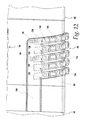
- FIG. 12 is an enlarged, fragmentary, elevation view of the tubular elements in FIGS. 6 and 7 , with the tubular elements relatively axially positioned as in FIG. 11 and in a first relative rotational position preparatory to relatively rotationally moving the tubular elements to direct the radially extending projections into the grooves;
- FIG. 13 is a view as in FIG. 12 and corresponding to the view in FIG. 10 ;
- FIG. 14 is a view as in FIGS. 12 and 13 and corresponding to the view in FIG. 9 ;
- FIG. 15 is an enlarged cross-sectional view of the tubular elements in FIGS. 6-12 operatively engaged and showing one of the projections in a representative groove with the tubular elements in any of the three relative axial positions depicted in FIGS. 9-11 and in the first relative rotational position;
- FIG. 16 corresponds to FIG. 15 with the tubular elements moved to a second relative rotational position
- FIG. 17 corresponds to FIG. 15 with the tubular elements moved to a third relative rotational position
- FIG. 18 corresponds to FIG. 15 with the tubular elements moved to a fourth relative rotational position
- FIG. 19 corresponds to FIG. 15 with the tubular elements moved to a fifth relative rotational position.
- FIG. 1 a schematic representation of one blower system, with the present invention incorporated, is shown at 10 .
- the blower system 10 consists of a blower 12 which generates forced air that is delivered to an outlet 14 .
- a first tubular element 16 is connected to the outlet 14 so that discharging fluid is communicated through the first tubular element 16 .
- the first tubular element 16 is in turn connected to a second tubular element 18 .
- the connection between the first and second tubular elements 16 , 18 is releasably established, according to the invention, through cooperating first and second connecting assemblies 20 , 22 , provided one each on the first tubular element 16 and second tubular element 18 , respectively.
- blower 12 could have virtually any of an infinite number of different styles and configurations i.e., back mounted, hand holdable, etc., so long as the same is capable of propelling a fluid through the first and second tubular elements 16 , 18 .
- FIG. 2 the inventive structure is shown schematically in a modified form of blower system 10 ′, incorporating the blower 12 and the first tubular element 16 .
- a second connecting assembly 24 cooperating with the first connecting assembly 20 on the first tubular element 16 , is provided on the blower 12 .
- first tubular element 16 is shown connected to a tubular end fitting element 26 through cooperation between the first connecting assembly 20 and a second connecting assembly 28 on the tubular end fitting element 26 .
- FIGS. 1-3 the elements are shown schematically so as to represent the inventive concept in a generic sense to encompass variations not shown or specifically described herein.
- the tubular elements 16 , 18 could have myriad different shapes, lengths, thickness, etc., other than those shown for exemplary purposes, herein.
- FIG. 4 An exemplary blower system, incorporating components of the type shown schematically in FIGS. 1-3 , is shown at 10 ′′ in FIG. 4 .
- the blower system 10 ′′ consists of a blower 12 mounted on the back of an operator 30 through a harness assembly 32 .
- the blower 12 generates a forced supply of air which is delivered to an outlet fitting 34 .
- a discharge tube assembly at 36 communicates the propelled air from the outlet fitting 34 through a discharge opening 38 at the outlet end of the discharge tube assembly 36 .
- the operator 30 manipulates a control arm 42 , and hand operated switches (not shown) thereon, to control the state of the blower 12 .
- the operator 30 can grasp the discharge tube assembly 36 and direct the outcoming air to an appropriate location.
- the particular configuration of the blower 12 is not critical to the present invention.
- the discharge tube assembly 36 consists of a first tubular element 46 , as show also in FIG. 5 .
- the first tubular element 46 has a cylindrical body 48 with a central axis 50 .
- the first tubular element 46 has an inlet end 52 , that is conventionally attached to the outlet fitting 34 , and an outlet end 54 , axially spaced from the inlet end 52 .
- the outlet end 54 of the first tubular element 46 is releasably connected to a second tubular element 56 , as shown also in FIGS. 5-7 .
- the second tubular element 56 has a cylindrical body 58 with a central axis 60 .
- the outlet end 54 of the first tubular element 46 is connected to the inlet end 62 of the second tubular element 56 .
- the second tubular element 56 has an outlet end 64 axially spaced from the inlet end 62 .
- the second tubular element 56 is in turn connected to a third tubular element/end fitting 66 , as seen additionally in FIGS. 6 and 7 .
- the third tubular element/end fitting 66 has a generally cylindrical body 68 with a central axis 70 .
- the third tubular element/end fitting 66 has an inlet end 72 and an outlet end 74 , spaced axially from the inlet end 72 and at which the discharge opening 38 is defined.
- the diameter of the body 68 tapers in diameter from a mid portion between the inlet and outlet ends 72 , 74 towards the outlet end 74 .
- the invention can be utilized to releasably connect: a) the outlet end 54 of the first tubular element 46 to the inlet end 62 of the second tubular element 56 ; and b) the outlet end 64 of the second tubular element 56 to the inlet end 72 of the third tubular element/end fitting 66 . While not shown as such, the inlet end 52 of the first tubular element 46 could be connected to the outlet fitting 34 utilizing the same inventive concept. Additional tubular elements (not shown) could be used to select the desired configuration of the discharge tube assembly 36 and connected using the inventive structure, as hereinbelow described.
- the tubular element 56 has a male portion 76 that fits within a female portion 78 on the tubular element/end fitting 66 .
- the male portion 76 has a radially outwardly facing surface 80 , with the female portion 78 having a radially inwardly facing surface 82 which fully surrounds the radially outwardly facing surface 80 with the male and female portions 76 , 78 operatively engaged, i.e. with the male portion 76 within the female portion 78 , as shown in FIGS. 9-19 .
- the tubular element 56 has a connecting assembly at 86 , with the tubular element/end fitting 66 having a connecting assembly 88 that cooperates with the connecting assembly 86 to releasably maintain the tubular element 56 and tubular element/end fitting 66 in their operative relationship through a range of different relative positions, as hereinafter described.
- the connecting assembly 86 consists of a pair of projections 90 , 92 extending radially outwardly from the surface 80 at the same circumferential location. As seen in FIG. 8 , the projections 90 , 92 are spaced from each other an axial distance L. Each of the projections 90 , 92 has an elongate shape, that is generally oval, with the lengths thereof, i.e. the lengths of the major axes, extending circumferentially along lines L 1 and L 2 , respectively. The lines L 1 and L 2 are substantially parallel to each other and make an angle ⁇ with respect to a reference plane P which is orthogonal to the axis 60 .
- the connecting assembly 86 includes additionally projections 90 ′, 92 ′, which have an identical construction to the projections 90 , 92 .
- the pairs of projections 90 , 92 , and 90 ′, 92 ′ are located diametrically opposite to each other.
- the projections 90 , 92 and 90 ′, 92 ′ coincide by visually rotating either pair of projections 90 , 92 or 90 ′, 92 ′ through 180° around the axis 60 .
- the connecting assembly 88 consists of two sets of diametrically oppositely situated grooves at 94 , 96 .
- the set of grooves 96 is identical to the set of grooves 94 , rotated through 180° around the axis 70 . The description herein will be limited to the exemplary set of grooves at 96 .
- the set of grooves 96 includes axially spaced, first, second, third, fourth, and fifth grooves 98 , 100 , 102 , 104 , 106 , respectively, each formed radially outside of the radially inwardly facing surface 82 .
- An axially extending entry groove 108 extends from the inlet end 72 so as to be contiguous with each of the grooves 98 - 106 .
- the entry groove 108 has a circumferential extent/width W that is slightly greater than the effective circumferential width W 1 for the projections 90 , 92 .
- the grooves 98 - 106 extend circumferentially on the order of 90-100° around the axis 70 , with successive grooves spaced equidistantly from each other axially along the female portion 78 .
- the spacing between the first and third grooves 98 , 102 , the second and fourth grooves 100 , 104 , and the third and fifth grooves 102 , 106 is equal to the distance L, which represents the axial spacing between the projections 90 , 92 and 90 ′, 92 ′.
- the grooves 98 - 106 are inclined to have an axial rise angle/pitch ⁇ ′, equal to the angle ⁇ , which represents the inclination angle for the lengths of the projections 90 , 92 relative to the reference plane P.
- the connecting assemblies 86 , 88 cooperate to controllably draw the tubular element 56 and tubular element/end fitting 66 axially towards each other to progressively increase the frictional holding force between the radially inwardly facing surface 82 on the female portion 78 and the radially outwardly facing surface 80 on the male portion 76 .
- the radially outwardly facing surface 80 on the male portion 76 has a tapering diameter. More specifically, at the free end 110 at the outlet end 64 of the tubular element 56 , the radially outwardly facing surface 80 has a diameter D which increases progressively axially to a location at 112 .
- the tapering portion between the free edge 110 and the location 112 has an axial dimension L 4 .
- the radially outwardly facing surface on the tubular element 56 has a substantially uniform diameter D 1 between the axial location 112 and a location at 114 , at which there are axially extending user gripping protrusions 116 , 117 , 118 , which each project radially outwardly sufficiently to be comfortably graspable by a user to facilitate imparting of a torque upon the body 58 .
- the tubular element/end fitting 66 has a uniform diameter D 2 , at least equal to, and preferably slightly greater than, D 1 , over an axial extent L 5 , extending from a free inlet end 119 of the tubular element/end fitting 66 to an axial location at 120 .
- the diameter of the surface 82 of the tubular element/end fitting 66 tapers correspondingly to the surface 80 between the location 112 and the free edge 110 on the tubular element 56 , so that the surfaces 80 , 82 closely engage over the lengths L 4 where the surfaces 80 , 82 taper.
- the surface 82 can taper progressively from a diameter larger than D 1 at the inlet end 72 to the axial location 121 .
- the diameters D, D 2 are chosen so that the outlet end 64 of the tubular element 56 can be guidingly directed, without significant impedance, through the inlet end 72 of the tubular element/end fitting 66 to allow axial overlapping of the tapered surfaces 80 , 82 .
- the frictional holding force between the tubular element 56 and the tubular element/end fitting 66 is increased by forcing the tapering portions of the surfaces 80 , 82 against each other.
- the axial penetration of the radially outwardly facing surface 80 is facilitated by making the thickness of the wall 126 on the body 68 non-uniform.
- the wall thickness may decrease progressively from the free end 121 towards the axial region at 128 adjacent to the fifth groove 106 , to permit the desired degree of penetration of the female portion 78 by the male portion 76 without excessive resistance.
- An exemplary range of wall thicknesses may be from 1.3-1.7 mm.
- the tubular element 56 and tubular element/end fitting 66 are concentrically aligned in a preassembly state, as shown in FIG. 8 .
- the relative rotational position of the tubular element 56 and tubular element 66 /end fitting 66 can be controlled so that the leading projection 92 is circumferentially registered with the entry groove 108 .
- the outlet end 64 of the second tubular element 56 can be directed loosely into the female portion 78 until the projection 92 resides against the free end 121 .
- the user can then slightly relatively rotate the tubular element 56 and tubular element/end fitting 66 to sense when the projection 92 registers with the entry groove 108 .
- tubular element 56 and tubular element/end fitting 66 can be moved axially towards each other to the point that the male portion 76 is snugly fit in the female portion 78 . This may occur with the projections 90 , 92 axially aligned with either the first and third grooves 98 , 102 , the second and fourth grooves 100 , 104 , or the third and fifth grooves 102 , 106 .
- the tubular element 56 and tubular element/end fitting 66 are in a first relative rotational position, as shown in FIGS. 12-15 , with the projections 90 , 92 aligned axially with a like number of grooves 98 - 106 . It should be noted that in FIGS.
- the radially inwardly and outwardly facing surfaces 80 , 82 are shown in radially spaced relationship for purposes of clarity. These surfaces 80 , 82 may actually be in closer proximity or against each other with the tubular element 56 and tubular element/end fitting 66 operatively engaged.
- the grooves 98 - 106 have enlarged entryways 130 , 132 , 134 , 136 , 138 , respectively, which guide movement of the projections 90 , 92 into the appropriate grooves 98 - 106 .
- the tapered configuration of the entryways 130 , 132 , 134 , 136 , 138 produces an adjusting camming action between the projections 90 , 92 and the converging surfaces defining the entryways 130 , 132 , 134 , 136 , 138 that effects a modicum of relative axial movement between the tubular element 56 and tubular element/end fitting 66 to cause consistent centered alignment to be achieved between the projections 90 , 92 and grooves 98 , 100 , 102 , 104 .
- each projection 90 , 92 , 90 ′, 92 ′ cooperates in the same manner with each groove 98 , 100 , 102 , 104 , 106 in the set 96 and each groove 98 ′, 100 ′, 102 ′, 104 ′, 106 ′ in the set 94 .
- the female portion 78 has a plurality, and in this case four, radially inwardly extending projections 140 , 142 , 144 , 146 which extend into the groove 98 .
- a first receptacle 148 is defined between circumferentially oppositely facing surfaces 150 , 152 on the adjacent projections 140 , 142 .
- a second receptacle 154 is bounded by circumferentially oppositely facing surfaces 156 , 158 on the projections adjacent 142 , 144 , respectively.
- a third receptacle 160 is bounded by circumferentially oppositely facing surfaces 162 , 164 on the adjacent projections 144 , 146 .
- a fourth receptacle 166 is bounded by circumferentially oppositely facing surfaces 168 , 170 , with the former on the projection 146 and the latter on a groove end wall 172 .
- the projection 90 is driven against the projection 140 . More specifically, a camming corner 174 on the projection 90 advances against an angled surface 176 on the projection 140 to wedge the projection 140 radially outwardly and/or the projection 90 radially inwardly. Deformation of one or both of the projections 90 , 140 is sufficient to allow the projection 90 to move circumferentially past the projection 140 and into the receptacle 148 with the tubular element 56 and tubular element/end fitting 66 in a second relative rotational position, as shown in FIG. 16 .
- the surfaces 150 , 152 on the projections 140 , 142 respectively confront circumferentially oppositely facing surfaces 178 , 180 on the projection 90 to confine the projection 90 within the receptacle 148 , preferably thereby permitting only a modicum of circumferential movement in either direction.
- a greater degree of circumferential movement of the projection 90 within the first receptacle 148 may be permitted, however, this might allow unwanted play in the connection between the tubular element 56 and the tubular element/end fitting 66 .
- the projection 90 can be moved serially into the receptacles 154 , 160 , 166 to achieve third, fourth and fifth relative rotational positions, between the tubular element 56 and tubular element/end fitting 66 , as shown in FIGS. 17-19 , respectively.
- This construction produces a detent-type mechanism wherein the user can sense the transition of the projection 90 from the entry groove 108 into each of the receptacles 148 , 154 , 160 , 166 .
- the groove 98 is configured with an axial rise angle ⁇ ′ equal to the angle ⁇ at which the length of the projection 90 extends relative to the reference plane P, as the projection 90 moves in the groove 98 , the tubular element 56 and tubular element/end fitting 66 cooperate to become progressively cammed axially towards each other to increase the frictional holding force between the tubular element 56 and tubular element/end fitting 66 .
- the user can relatively rotate the tubular element 56 and tubular element/end fitting 66 to an extent to situate the projection 90 in the particular receptacle 148 , 154 , 160 , 166 that produces the desired frictional holding force.
- the user can back the projection 90 out of the groove 98 and into the groove 108 to place the tubular element 56 and tubular element/end fitting 66 in a different relative axial position, as hereinafter explained.
- a separate camming corner 184 on the projection 90 consecutively engages the projections 146 , 144 , 142 , 140 .
- the projection 90 is deformed radially inwardly and/or the projections 146 , 144 , 142 , 140 are deformed radially outwardly to allow passage of the projection 90 from a position within the recess 166 back into the entry groove 108 .
- the user can then place the tubular element 56 and tubular element/end fitting 66 in a second relative axial position, show in FIGS. 10 and 13 , wherein the projection 90 axially aligns with the entryway 132 to the second groove 100 and the projection 92 axially aligns with the entryway 136 to the fourth groove 104 .
- the tubular element 56 and tubular element/end fitting 66 can then be relatively rotated, as shown sequentially in FIGS. 15-19 , to progressively increase the frictional holding force between the tubular element 56 and tubular element/end fitting 66 .
- the projection 90 can be resituated back into the entry groove 108 after which the tubular element 56 and tubular element/end fitting 66 can be placed in a third relative axial position, as shown in FIGS. 11 and 12 , wherein the projection 90 aligns with the third groove 102 and the projection 92 aligns with the fifth 106 , after which the aforementioned steps can be reperformed to change the relative rotational positions between the tubular element 56 and tubular element/end fitting 66 .
- the axial positions of the grooves 98 - 106 are set so that the maximum frictional holding force that can be generated with the tubular element 56 and tubular element/end fitting 66 in the first relative axial position and moved to the fifth relative rotational position is slightly less than that which results with the tubular element 56 and tubular element/end fitting 66 in the second relative axial position of FIG. 10 with the tubular element 56 and tubular element/end fitting 66 in the first relative rotational position. Accordingly, a smooth transition of frictional holding force can be set through the entire permissible range. However, this particular feature is not required.
- the inventive concept can be used with virtually any connection between telescopingly engaged parts.
- the inlet end 52 of the first tubular element 46 is connected to a fitting on the blower 12 having a conventional construction, the inventive concept can be used at this location as well.
- the inventive structure lends itself to manufacture using a number of different moldable plastic or non-plastic materials well known to those skilled in this art.
- a single projection 90 , 92 , 90 ′, 92 ′ would function consistently with the invention. Still further, while cooperating projections 90 , 92 , 90 ′, 92 ′ and sets of grooves 94 , 96 are shown at diametrically opposite locations, a single projection 90 , 92 , 90 ′, 92 ′ capable of cooperating with a single set of grooves 94 , 96 is contemplated by the invention.
- the multiple projections 90 , 92 , 90 ′, 92 ′ at each diametrically opposite location and the provision of cooperating projections 90 , 92 , 90 ′, 92 ′ and sets of grooves 94 , 96 at separate circumferential locations is preferred in that this arrangement generally provides more positive interaction of the tubular element 56 and tubular element/end fitting 66 and potentially affords greater overall stability and strength to the joined tubular element 56 and tubular element/end fitting 66 .
- the elongate, oval configuration of the projections 90 , 92 , 90 ′, 92 ′ is only exemplary and preferred because of the substantial guide surface area that this configuration affords.
- the projections could take virtually any projecting form, such as circular, triangular, square, etc.
- grooves 98 , 100 , 102 , 104 , 106 are design consideration and could range from as few as one to any number greater than the five shown.
- indicia as shown at 186 in FIG. 8 , or stop structure might be provided to allow the user to consistently visually or tactilely sense positioning of the tubular element 56 and tubular element/end fitting 66 in the different relative axial positions.
- indicia 190 , 192 may be provided on the tubular element/end fitting 66 at circumferentially spaced locations coinciding, one each, with the circumferential locations of the receptacles 148 , 154 , 160 , 166 .
- a mark 194 on the tubular element 56 coincides circumferentially with the projections 190 , 192 and is aligned with the receptacle 148 , 154 , 160 , 166 in which the projections 190 , 192 are currently releasably held. This allows the user to visually identify the current relative rotational position of the tubular element 56 and the tubular element/end fitting 66 and facilitates selective repositioning of the same by relative rotation.
- the limitation of penetration of the tubular element/end fitting 66 by the tubular element 56 is determined by the projections 92 , 92 ′ which abut shoulders 196 (one shown in FIG. 13 ) at the ends of the entry grooves 108 , 108 ′.
- any of the tubular elements can be made in multiple pieces.
- a tubular element may have one part relative to which a portion having the connecting assembly thereon is relatively movable, as by rotation.
- the single and multi-part constructions are treated equivalently as if one part.
Landscapes
- Engineering & Computer Science (AREA)
- General Engineering & Computer Science (AREA)
- Mechanical Engineering (AREA)
- Quick-Acting Or Multi-Walled Pipe Joints (AREA)
Abstract
Description
Claims (23)
Priority Applications (1)
| Application Number | Priority Date | Filing Date | Title |
|---|---|---|---|
| US10/646,323 US8210577B2 (en) | 2003-08-22 | 2003-08-22 | Connecting system for telescopingly engaged elements and method of maintaining the elements together using the system |
Applications Claiming Priority (1)
| Application Number | Priority Date | Filing Date | Title |
|---|---|---|---|
| US10/646,323 US8210577B2 (en) | 2003-08-22 | 2003-08-22 | Connecting system for telescopingly engaged elements and method of maintaining the elements together using the system |
Publications (2)
| Publication Number | Publication Date |
|---|---|
| US20050040648A1 US20050040648A1 (en) | 2005-02-24 |
| US8210577B2 true US8210577B2 (en) | 2012-07-03 |
Family
ID=34194503
Family Applications (1)
| Application Number | Title | Priority Date | Filing Date |
|---|---|---|---|
| US10/646,323 Expired - Fee Related US8210577B2 (en) | 2003-08-22 | 2003-08-22 | Connecting system for telescopingly engaged elements and method of maintaining the elements together using the system |
Country Status (1)
| Country | Link |
|---|---|
| US (1) | US8210577B2 (en) |
Cited By (3)
| Publication number | Priority date | Publication date | Assignee | Title |
|---|---|---|---|---|
| WO2015027277A1 (en) * | 2013-08-27 | 2015-03-05 | Twist4Lock Pty Ltd As Trustee Of The T4L Trust | System and method of releasably connecting pipe sections |
| US20150376912A1 (en) * | 2014-06-28 | 2015-12-31 | Evrio, Inc. | Modular System Including Shaft Segments Having Configuration and Breakdown Attachments |
| US20200305360A1 (en) * | 2017-09-29 | 2020-10-01 | Husqvarna Ab | An Adjustable Nozzle For a Blower |
Families Citing this family (9)
| Publication number | Priority date | Publication date | Assignee | Title |
|---|---|---|---|---|
| US20110179590A1 (en) * | 2010-01-28 | 2011-07-28 | David Andrew Klimas | Swimming Pool Cleaners, and Associated Hoses and Connectors for Use with the Same |
| US10820763B2 (en) * | 2014-01-06 | 2020-11-03 | H-P Products, Inc. | Central vacuum system and inlet valves therefor |
| DE102014119249A1 (en) * | 2014-12-19 | 2016-06-23 | Festool Gmbh | Suction hose fitting |
| DE102014119243A1 (en) * | 2014-12-19 | 2016-06-23 | Festool Gmbh | Suction hose fitting |
| DE102014119239A1 (en) * | 2014-12-19 | 2016-06-23 | Festool Gmbh | Suction hose fitting |
| GB201608603D0 (en) * | 2016-05-16 | 2016-06-29 | Medical Device Creations Ltd | Improved fluid line connector device |
| CN107348928B (en) * | 2017-06-23 | 2019-09-20 | 珠海格力电器股份有限公司 | Exhaust system reaches dish washer including it |
| US11684006B2 (en) * | 2018-06-01 | 2023-06-27 | Deere & Company | Tool-free coupling structure in agricultural machines |
| DE102019109902B4 (en) * | 2019-04-15 | 2020-12-31 | Linhardt Gmbh & Co. Kg | Container packaging with safety lock |
Citations (14)
| Publication number | Priority date | Publication date | Assignee | Title |
|---|---|---|---|---|
| US1099670A (en) * | 1914-06-09 | Gurdon W Merrell | Pneumatic-tool retainer. | |
| US1476119A (en) * | 1921-12-20 | 1923-12-04 | Cora M Van Nagell | Hose coupling |
| US1951754A (en) * | 1931-01-21 | 1934-03-20 | Early L Gilbert | Adjustable standard |
| US3803532A (en) * | 1973-03-19 | 1974-04-09 | Cyprus Mines Corp | Electrical conduit |
| US4046279A (en) * | 1974-04-19 | 1977-09-06 | Hilti Aktiengesellschaft | Packing container for objects of variable lengths |
| US4157153A (en) * | 1978-03-08 | 1979-06-05 | General Electric Company | Aluminum tube joint design |
| US4911573A (en) * | 1987-12-24 | 1990-03-27 | Nuova Omec S.R.L. | Rigid axial retainer |
| US5054159A (en) * | 1989-09-25 | 1991-10-08 | Richardson Paul D | Debris removal apparatus for power blowers |
| US5926910A (en) * | 1996-06-21 | 1999-07-27 | Kioritz Corporation | Blower pipe |
| US6108865A (en) * | 1998-07-28 | 2000-08-29 | Andreas Stihl Ag & Co. | Portable handheld blower/vacuum apparatus |
| US6447021B1 (en) * | 1999-11-24 | 2002-09-10 | Michael Jonathon Haynes | Locking telescoping joint for use in a conduit connected to a wellhead |
| US20030151251A1 (en) * | 2002-02-13 | 2003-08-14 | Trans Continental Equipment Ltd. | Furnace pipe connection |
| US6811190B1 (en) * | 2001-08-09 | 2004-11-02 | Metal-Fab, Inc. | Tab-lock fastener for interlocking vent pipe |
| US6908250B2 (en) * | 2002-10-25 | 2005-06-21 | Greenlee Textron Inc. | Retainer for retaining collapsed poles within another pole |
Family Cites Families (3)
| Publication number | Priority date | Publication date | Assignee | Title |
|---|---|---|---|---|
| US2673751A (en) * | 1950-12-05 | 1954-03-30 | Jones & Laughlin Steel Corp | Metal pipe and coupling therefor |
| US4321911A (en) * | 1979-08-15 | 1982-03-30 | Offutt Worthington W | Modular solar collector system |
| US6283511B1 (en) * | 1998-08-24 | 2001-09-04 | Well Engineering Partners, B.V. | Pipe coupling |
-
2003
- 2003-08-22 US US10/646,323 patent/US8210577B2/en not_active Expired - Fee Related
Patent Citations (14)
| Publication number | Priority date | Publication date | Assignee | Title |
|---|---|---|---|---|
| US1099670A (en) * | 1914-06-09 | Gurdon W Merrell | Pneumatic-tool retainer. | |
| US1476119A (en) * | 1921-12-20 | 1923-12-04 | Cora M Van Nagell | Hose coupling |
| US1951754A (en) * | 1931-01-21 | 1934-03-20 | Early L Gilbert | Adjustable standard |
| US3803532A (en) * | 1973-03-19 | 1974-04-09 | Cyprus Mines Corp | Electrical conduit |
| US4046279A (en) * | 1974-04-19 | 1977-09-06 | Hilti Aktiengesellschaft | Packing container for objects of variable lengths |
| US4157153A (en) * | 1978-03-08 | 1979-06-05 | General Electric Company | Aluminum tube joint design |
| US4911573A (en) * | 1987-12-24 | 1990-03-27 | Nuova Omec S.R.L. | Rigid axial retainer |
| US5054159A (en) * | 1989-09-25 | 1991-10-08 | Richardson Paul D | Debris removal apparatus for power blowers |
| US5926910A (en) * | 1996-06-21 | 1999-07-27 | Kioritz Corporation | Blower pipe |
| US6108865A (en) * | 1998-07-28 | 2000-08-29 | Andreas Stihl Ag & Co. | Portable handheld blower/vacuum apparatus |
| US6447021B1 (en) * | 1999-11-24 | 2002-09-10 | Michael Jonathon Haynes | Locking telescoping joint for use in a conduit connected to a wellhead |
| US6811190B1 (en) * | 2001-08-09 | 2004-11-02 | Metal-Fab, Inc. | Tab-lock fastener for interlocking vent pipe |
| US20030151251A1 (en) * | 2002-02-13 | 2003-08-14 | Trans Continental Equipment Ltd. | Furnace pipe connection |
| US6908250B2 (en) * | 2002-10-25 | 2005-06-21 | Greenlee Textron Inc. | Retainer for retaining collapsed poles within another pole |
Cited By (3)
| Publication number | Priority date | Publication date | Assignee | Title |
|---|---|---|---|---|
| WO2015027277A1 (en) * | 2013-08-27 | 2015-03-05 | Twist4Lock Pty Ltd As Trustee Of The T4L Trust | System and method of releasably connecting pipe sections |
| US20150376912A1 (en) * | 2014-06-28 | 2015-12-31 | Evrio, Inc. | Modular System Including Shaft Segments Having Configuration and Breakdown Attachments |
| US20200305360A1 (en) * | 2017-09-29 | 2020-10-01 | Husqvarna Ab | An Adjustable Nozzle For a Blower |
Also Published As
| Publication number | Publication date |
|---|---|
| US20050040648A1 (en) | 2005-02-24 |
Similar Documents
| Publication | Publication Date | Title |
|---|---|---|
| US8210577B2 (en) | Connecting system for telescopingly engaged elements and method of maintaining the elements together using the system | |
| US6391414B1 (en) | Structure and method for joining parts | |
| US9163667B2 (en) | Slide bearing, slide bearing system and assembly of a slide bearing system | |
| US6231552B1 (en) | Threaded latching mechanism | |
| US4375342A (en) | Two-piece plastic fastener | |
| AU722577B2 (en) | Serviceable rivet | |
| US7073997B2 (en) | Apparatus and method for holding a piece in a bore | |
| JPH01167499A (en) | Integral connecting structure of water pump-impeller made of synthetic plastic | |
| US8784029B2 (en) | Insertion type furniture connector | |
| EP2436262A2 (en) | Blower apparatus and air conveying apparatus | |
| EP3012006B1 (en) | Building block structure | |
| EP0965002B1 (en) | Structure and method for joining parts | |
| US9434065B2 (en) | Set of display board and socket | |
| CN110816758A (en) | Locking means and aquatic sports device take off | |
| EP1592891B1 (en) | Device for holding a piece in a bore | |
| CN105317802A (en) | Blind rivet for connecting composite materials capable of adjusting interlayer thickness range | |
| CN219062500U (en) | Ball valve | |
| US6443037B1 (en) | Screwdriver grip structure | |
| US9909606B2 (en) | Two-piece pallet fastener | |
| CN217633276U (en) | Reinforcing member, connecting assembly and connecting system | |
| CN201696421U (en) | Locking and connecting structure | |
| EP0993343A1 (en) | Deposition of beads of material | |
| CN210423304U (en) | Barrel connecting device | |
| CA1051699A (en) | Connector member for tip of fastener | |
| EP3728922B1 (en) | Tube connection |
Legal Events
| Date | Code | Title | Description |
|---|---|---|---|
| AS | Assignment |
Owner name: ECHO, INCORPORATED, ILLINOIS Free format text: ASSIGNMENT OF ASSIGNORS INTEREST;ASSIGNORS:SMOLENSKI, MARK;COMERFORD, MICHAEL G.;WILL, LARRY N.;AND OTHERS;REEL/FRAME:020416/0269;SIGNING DATES FROM 20030818 TO 20030820 Owner name: ECHO, INCORPORATED, ILLINOIS Free format text: ASSIGNMENT OF ASSIGNORS INTEREST;ASSIGNORS:SMOLENSKI, MARK;COMERFORD, MICHAEL G.;WILL, LARRY N.;AND OTHERS;SIGNING DATES FROM 20030818 TO 20030820;REEL/FRAME:020416/0269 |
|
| ZAAA | Notice of allowance and fees due |
Free format text: ORIGINAL CODE: NOA |
|
| ZAAB | Notice of allowance mailed |
Free format text: ORIGINAL CODE: MN/=. |
|
| STCF | Information on status: patent grant |
Free format text: PATENTED CASE |
|
| FPAY | Fee payment |
Year of fee payment: 4 |
|
| MAFP | Maintenance fee payment |
Free format text: PAYMENT OF MAINTENANCE FEE, 8TH YEAR, LARGE ENTITY (ORIGINAL EVENT CODE: M1552); ENTITY STATUS OF PATENT OWNER: LARGE ENTITY Year of fee payment: 8 |
|
| FEPP | Fee payment procedure |
Free format text: MAINTENANCE FEE REMINDER MAILED (ORIGINAL EVENT CODE: REM.); ENTITY STATUS OF PATENT OWNER: LARGE ENTITY |
|
| LAPS | Lapse for failure to pay maintenance fees |
Free format text: PATENT EXPIRED FOR FAILURE TO PAY MAINTENANCE FEES (ORIGINAL EVENT CODE: EXP.); ENTITY STATUS OF PATENT OWNER: LARGE ENTITY |
|
| STCH | Information on status: patent discontinuation |
Free format text: PATENT EXPIRED DUE TO NONPAYMENT OF MAINTENANCE FEES UNDER 37 CFR 1.362 |
|
| FP | Lapsed due to failure to pay maintenance fee |
Effective date: 20240703 |