EP0676619B1 - Tastelement für die Steuerung von Elektromotoren - Google Patents
Tastelement für die Steuerung von Elektromotoren Download PDFInfo
- Publication number
- EP0676619B1 EP0676619B1 EP95250035A EP95250035A EP0676619B1 EP 0676619 B1 EP0676619 B1 EP 0676619B1 EP 95250035 A EP95250035 A EP 95250035A EP 95250035 A EP95250035 A EP 95250035A EP 0676619 B1 EP0676619 B1 EP 0676619B1
- Authority
- EP
- European Patent Office
- Prior art keywords
- hall sensor
- pushbutton control
- permanent magnet
- pushrod
- hall
- Prior art date
- Legal status (The legal status is an assumption and is not a legal conclusion. Google has not performed a legal analysis and makes no representation as to the accuracy of the status listed.)
- Expired - Lifetime
Links
- GYHNNYVSQQEPJS-UHFFFAOYSA-N Gallium Chemical compound [Ga] GYHNNYVSQQEPJS-UHFFFAOYSA-N 0.000 claims description 2
- AQLMHYSWFMLWBS-UHFFFAOYSA-N arsenite(1-) Chemical compound O[As](O)[O-] AQLMHYSWFMLWBS-UHFFFAOYSA-N 0.000 claims description 2
- KPLQYGBQNPPQGA-UHFFFAOYSA-N cobalt samarium Chemical compound [Co].[Sm] KPLQYGBQNPPQGA-UHFFFAOYSA-N 0.000 claims description 2
- 229910052733 gallium Inorganic materials 0.000 claims description 2
- 229910000938 samarium–cobalt magnet Inorganic materials 0.000 claims description 2
- 229910052796 boron Inorganic materials 0.000 claims 1
- 238000005259 measurement Methods 0.000 description 11
- 230000000694 effects Effects 0.000 description 5
- 230000006698 induction Effects 0.000 description 5
- 239000000523 sample Substances 0.000 description 5
- BGPVFRJUHWVFKM-UHFFFAOYSA-N N1=C2C=CC=CC2=[N+]([O-])C1(CC1)CCC21N=C1C=CC=CC1=[N+]2[O-] Chemical compound N1=C2C=CC=CC2=[N+]([O-])C1(CC1)CCC21N=C1C=CC=CC1=[N+]2[O-] BGPVFRJUHWVFKM-UHFFFAOYSA-N 0.000 description 4
- 239000004065 semiconductor Substances 0.000 description 3
- 230000005355 Hall effect Effects 0.000 description 2
- 238000013459 approach Methods 0.000 description 2
- 230000008859 change Effects 0.000 description 2
- 239000004020 conductor Substances 0.000 description 2
- 230000001276 controlling effect Effects 0.000 description 2
- 238000010586 diagram Methods 0.000 description 2
- 230000005284 excitation Effects 0.000 description 2
- 230000002349 favourable effect Effects 0.000 description 2
- 239000000463 material Substances 0.000 description 2
- QJVKUMXDEUEQLH-UHFFFAOYSA-N [B].[Fe].[Nd] Chemical compound [B].[Fe].[Nd] QJVKUMXDEUEQLH-UHFFFAOYSA-N 0.000 description 1
- 230000004888 barrier function Effects 0.000 description 1
- 230000008901 benefit Effects 0.000 description 1
- 230000033228 biological regulation Effects 0.000 description 1
- 230000005540 biological transmission Effects 0.000 description 1
- 239000002800 charge carrier Substances 0.000 description 1
- 230000001419 dependent effect Effects 0.000 description 1
- 238000001514 detection method Methods 0.000 description 1
- 230000006872 improvement Effects 0.000 description 1
- 230000001939 inductive effect Effects 0.000 description 1
- 229910052751 metal Inorganic materials 0.000 description 1
- 239000002184 metal Substances 0.000 description 1
- 150000002739 metals Chemical class 0.000 description 1
- 229910001172 neodymium magnet Inorganic materials 0.000 description 1
- 230000035699 permeability Effects 0.000 description 1
- 230000001105 regulatory effect Effects 0.000 description 1
Images


Classifications
-
- H—ELECTRICITY
- H03—ELECTRONIC CIRCUITRY
- H03K—PULSE TECHNIQUE
- H03K17/00—Electronic switching or gating, i.e. not by contact-making and –breaking
- H03K17/94—Electronic switching or gating, i.e. not by contact-making and –breaking characterised by the way in which the control signals are generated
- H03K17/965—Switches controlled by moving an element forming part of the switch
- H03K17/97—Switches controlled by moving an element forming part of the switch using a magnetic movable element
-
- G—PHYSICS
- G01—MEASURING; TESTING
- G01D—MEASURING NOT SPECIALLY ADAPTED FOR A SPECIFIC VARIABLE; ARRANGEMENTS FOR MEASURING TWO OR MORE VARIABLES NOT COVERED IN A SINGLE OTHER SUBCLASS; TARIFF METERING APPARATUS; MEASURING OR TESTING NOT OTHERWISE PROVIDED FOR
- G01D5/00—Mechanical means for transferring the output of a sensing member; Means for converting the output of a sensing member to another variable where the form or nature of the sensing member does not constrain the means for converting; Transducers not specially adapted for a specific variable
- G01D5/12—Mechanical means for transferring the output of a sensing member; Means for converting the output of a sensing member to another variable where the form or nature of the sensing member does not constrain the means for converting; Transducers not specially adapted for a specific variable using electric or magnetic means
- G01D5/14—Mechanical means for transferring the output of a sensing member; Means for converting the output of a sensing member to another variable where the form or nature of the sensing member does not constrain the means for converting; Transducers not specially adapted for a specific variable using electric or magnetic means influencing the magnitude of a current or voltage
- G01D5/142—Mechanical means for transferring the output of a sensing member; Means for converting the output of a sensing member to another variable where the form or nature of the sensing member does not constrain the means for converting; Transducers not specially adapted for a specific variable using electric or magnetic means influencing the magnitude of a current or voltage using Hall-effect devices
- G01D5/145—Mechanical means for transferring the output of a sensing member; Means for converting the output of a sensing member to another variable where the form or nature of the sensing member does not constrain the means for converting; Transducers not specially adapted for a specific variable using electric or magnetic means influencing the magnitude of a current or voltage using Hall-effect devices influenced by the relative movement between the Hall device and magnetic fields
-
- H—ELECTRICITY
- H02—GENERATION; CONVERSION OR DISTRIBUTION OF ELECTRIC POWER
- H02K—DYNAMO-ELECTRIC MACHINES
- H02K11/00—Structural association of dynamo-electric machines with electric components or with devices for shielding, monitoring or protection
- H02K11/20—Structural association of dynamo-electric machines with electric components or with devices for shielding, monitoring or protection for measuring, monitoring, testing, protecting or switching
- H02K11/21—Devices for sensing speed or position, or actuated thereby
- H02K11/215—Magnetic effect devices, e.g. Hall-effect or magneto-resistive elements
-
- H—ELECTRICITY
- H02—GENERATION; CONVERSION OR DISTRIBUTION OF ELECTRIC POWER
- H02K—DYNAMO-ELECTRIC MACHINES
- H02K11/00—Structural association of dynamo-electric machines with electric components or with devices for shielding, monitoring or protection
- H02K11/30—Structural association with control circuits or drive circuits
- H02K11/33—Drive circuits, e.g. power electronics
Definitions
- the invention relates to a probe element for the control of electric motors, in particular for cranes and other funding, according to the preamble of claim 1.
- US-A-4 950 922 describes a probe element for controlling electric motors with one the control signal triggering push rod, which is slidably mounted in a housing.
- a permanent magnet attached to the button plunger is essentially perpendicular to the active area of a Hall sensor adjustable and single-pole axially on the active area of the Hall sensor approachable or movable away again.
- a pushbutton element for the control of electric motors is known with a push button tappet that triggers the control signal and can be moved in a housing is stored, and wherein an electronic circuit is provided, one against one Hall sensor adjustable permanent magnet includes and in the probe housing is integrated.
- the magnetoresistive effect forms the physical basis for Hall and field plate sensors: Moving charge carriers are affected by a vertical magnetic field B. Lorentz force deflected laterally. Due to the resulting cross field in the middle of the Semiconductor wafer is in an equilibrium state.
- the Hall voltage UH is proportional to the magnetic field B and the control current i and inversely proportional to the layer thickness d and the charge concentration n.
- RH is referred to as the Hall constant. If you look at the current paths, they are also rotated by the Hall angle in the vicinity of the current electrodes. For small Hall angles (equal to or less than 0.45) one obtains a quadratic dependence of the resistance on the magnetic field B.
- R 0 is the resistance without a magnetic field.
- Hall sensors are therefore active four poles with a current and Hall voltage path, while field plates represent passive magnetic field-dependent resistors.
- All magnetic field sensors that are not used for direct measurement of magnetic fields use the magnetic field as a transmission medium between one to be detected physical quantity (position, speed, current, power, etc.) and the sensor.
- the Correct design of the magnetic circuit is therefore a prerequisite for the full use of the Sensor properties.
- the simplest magnetic circuit consists of a permanent magnet and a sensor. Passing soft magnetic parts lead to an induction change by the sensor is detected.
- a closed magnetic circuit excited with a permanent magnet becomes Position detection is often implemented as a magnetic fork barrier. Closed magnetic circuits with electrical excitation form the basis for potential-free current and power measurement.
- the generated by the current to be measured Excitation provides an induction, which is measured by a Hall sensor in the air gap. It there is a linear relationship between measurement current and induction.
- position sensors are used for non-contact and thus wear-free recording of control parameters such as distance, angle and speed.
- Hall sensors are particularly suitable for this task.
- Hall sensors are semiconductor components whose electrical behavior is caused by magnetic fields can be influenced.
- the basis is the Hall effect mentioned.
- the magnetic field causes those flowing through the leaflet in the longitudinal direction Electrons are deflected to the side.
- the Hall voltage can then be found on the side contacts tap.
- This Hall voltage is not just the size of the current and the magnetic induction, but mainly on the speed at which the Electrons flow through the band-shaped conductor. Many cause slow effects in metals Electrons flow and the Hall voltage is barely measurable. Very big against it is the Hall effect in certain semiconductor materials where the current is few Electrons are carried at high speed.
- Components based on this effect deliver an electrical signal when one Magnetic field affects them. If they are connected to a permanent magnet, it changes their Hall voltage when a soft magnetic body approaches the existing one Magnetic field affected. In comparison with inductive sensors, they have the advantage that their Signal voltage is independent of the speed at which to be registered Body approaches the sensor. According to the different requirements for the Different embodiments are offered to sensors.
- Touch elements for the control of electric motors with multiple speeds are said to specify a higher or lower speed depending on the actuation path.
- To the Steplessly controlling speed moves e.g. the button a grinder on one Resistance track.
- the variable electrical attacked along the ram path Resistance then specifies a speed depending on the path.
- the size of a pushbutton for the control of electric motors should only continue of such an external dimension that it can be found in other devices, e.g. one Hand switch and the like Finds space.
- the present invention is therefore based on the object, a probe element for Control of electric motors in the manner of non-contact position measurement with Hall sensors to create that can be arranged in a variety of other switching devices can.
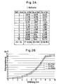
- Resistor R 4 is required to adjust to the initial or final value. It can be shown to what extent the curve changes when the resistor R 4 is adjusted. In the case described, this is done with a decade of resistance. It can be seen from the attached table and the drawing that the curve has a flat slope in the beginning and only barely reaches the end value when the resistance becomes less than 22 k ohms. It is different if you set the resistance to 22.6 k ohms. Here the slope is initially steep and the curve is almost optimal from the entire course.
- the permanent magnet made of samarium cobalt and neodymium iron boron. These materials are characterized by a high Energy density with small volumes.
- Another improvement of the invention is given in that the Hall sensor Gallium arsenite (GaAs) exists.
- GaAs Gallium arsenite
- Fig. 1 shows a circuit that is used for position measurement with a Hall sensor.
- Push button plunger 1 is movable in a housing 2.
- the push button plunger 1 carries a permanent magnet 4.
- a Hall sensor 5 has an active surface 5a, and the push button plunger 1 is perpendicular to active surface 5a back and forth in the direction of movement 6. The Return movement takes place by a not shown Return spring.
- 2A shows the extent to which the curve changes when a resistance R 4 is adjusted. This is done with a decade of resistance. 2A and 2B then show that the curve has a flat slope in the initial region and only barely reaches the final value when the resistance becomes less than 22 kOhm. It is different if you set the resistance to 22.6 kOhm. Here the slope is initially steep and the curve is optimal from the whole course.
- the resistor R 4 with the value 22 kOhm was firmly soldered in, and then the switch could be clamped back into the measuring device.
- the push-button tappet 1 was then pressed five times at the same distance, from which the mean value was calculated and shown in the characteristic curve (FIG. 3B).
- the desired success is achieved in the measurements based on the electronic circuit 3 with the Hall sensor 5.
- a first requirement based on an exponential curve ie a good possibility of regulating the lower speeds of an electric motor, was met.
- it means no problem to compare with the resistor R 4 and at the same time to change the course of the curve. It can be determined beforehand which characteristic curve is suitable for the practical case. If, for example, the slope in the initial area is important or if the final value of 10 volts is reached exactly, the course of the curve can be changed accordingly.
- the effects of the different resistance dimensions of R 4 on the characteristic curve are shown in the first series of measurements (FIG. 2A).
- the circuit complexity for the push button plunger 1 with the Hall sensor 5 is relatively low and inexpensive, with the slightly higher costs for the Hall sensor 5 and the permanent magnet 4 are not significant.
Landscapes
- Engineering & Computer Science (AREA)
- Microelectronics & Electronic Packaging (AREA)
- Power Engineering (AREA)
- Physics & Mathematics (AREA)
- General Physics & Mathematics (AREA)
- Measuring Magnetic Variables (AREA)
- Transmission And Conversion Of Sensor Element Output (AREA)
- Measurement Of Length, Angles, Or The Like Using Electric Or Magnetic Means (AREA)
- Hall/Mr Elements (AREA)
- Catching Or Destruction (AREA)
- Push-Button Switches (AREA)
- Control Of Ac Motors In General (AREA)
Description
- Fig. 1
- eine in einem Gehäuse integrierte elektronische Schaltung,
- Fig. 2A
- die Ergebnisse einer ersten Meßreihe als Tabelle,
- Fig. 2B
- das zu Fig. 2a gehörige Diagramm,
- Fig. 3A
- die Ergebnisse einer zweiten Meßreihe, ebenfalls in Tabellenform und
- Fig. 3B
- das zu Fig. 3A gehörige Diagramm.
- 1
- Tasterstößel
- 2
- Tastelement-Gehäuse
- 3
- elektronische Schaltung
- 4
- Permanent-Magnet
- 5
- Hall-Sensor
- 5a
- aktive Fläche
- 6
- Bewegungsrichtung
Claims (4)
- Tastelement für die Steuerung von Elektromotoren, insbesondere für Krane und andere Fördermittel,dadurch gekennzeichnet,mit einem das Steuersignal auslösenden Tasterstößel (1), der in einem Gehäuse (2) verschiebbar gelagert ist,mit einem an dem Tasterstößel (1) befestigten Permanent-Magneten (4), der im wesentlichen senkrecht gegen die aktive Fläche eines Hall-Sensors (5) anstellbar und einpolig axial auf die aktive Fläche des Hall-Sensors (5) annäherbar bzw. wieder wegbewegbar ist, und mit einer in das Gehäuse (2) integrierten, den Hall-Sensor (5), umfassenden elektronischen Schaltung (3),
daß die elektronische Schaltung (3) als Ausgangsspannung Ua eine Differenzspannung abgibt, die aus der hyperbolisch verlaufenden Ausgangsspannung des Hall-Sensors (5) und einer Konstantspannung gebildet ist und deren Kurvenverlauf durch Einstellung der Konstantspannung über die Wegstrecke des Tasterstößels (1) an eine exponentielle Kurve angenähert ist. - Tastelement nach Anspruch 1,
dadruch gekennzeichnet,
daß der Permanent-Magnet (4) an dem Tasterstößel (1) justierbar befestigt ist. - Tastelement nach einem der Ansprüche 1 und 2,
dadurch gekennzeichnet,
daß der Permanent-Magnet (4) aus Samarium-Cobalt oder aus Neodym-Eisen-Bor besteht. - Tastelement nach einem der Ansprüche 1 bis 3,
dadurch gekennzeichnet,
daß der Hall-Sensor (5) aus Galliumarsenit besteht.
Applications Claiming Priority (2)
| Application Number | Priority Date | Filing Date | Title |
|---|---|---|---|
| DE4412555 | 1994-04-11 | ||
| DE4412555A DE4412555C2 (de) | 1994-04-11 | 1994-04-11 | Ein analoges Steuersignal abgebendes Tastelement für die Steuerung von Elektromotoren |
Publications (2)
| Publication Number | Publication Date |
|---|---|
| EP0676619A1 EP0676619A1 (de) | 1995-10-11 |
| EP0676619B1 true EP0676619B1 (de) | 2000-03-22 |
Family
ID=6515182
Family Applications (1)
| Application Number | Title | Priority Date | Filing Date |
|---|---|---|---|
| EP95250035A Expired - Lifetime EP0676619B1 (de) | 1994-04-11 | 1995-02-13 | Tastelement für die Steuerung von Elektromotoren |
Country Status (4)
| Country | Link |
|---|---|
| US (1) | US5631530A (de) |
| EP (1) | EP0676619B1 (de) |
| JP (1) | JPH07296671A (de) |
| DE (1) | DE4412555C2 (de) |
Families Citing this family (8)
| Publication number | Priority date | Publication date | Assignee | Title |
|---|---|---|---|---|
| DE10043739A1 (de) * | 2000-09-05 | 2002-03-21 | Fico Cables Sa | Handbremse |
| KR101379994B1 (ko) * | 2012-11-21 | 2014-04-02 | 대성전기공업 주식회사 | 비접촉식 스위치 |
| JP5862645B2 (ja) * | 2013-11-29 | 2016-02-16 | 株式会社デンソー | 駆動装置 |
| CN204013472U (zh) * | 2014-06-24 | 2014-12-10 | 中兴通讯股份有限公司 | 一种按键 |
| US9776692B2 (en) | 2014-07-02 | 2017-10-03 | S.P. Cramer & Associates, Inc. | Single-platform integrated aquatic species and habitat sampling system |
| KR101992975B1 (ko) | 2019-02-12 | 2019-06-27 | 주식회사 대산이노텍 | 다단 속도 제어 가능한 호이스트의 콘트롤러 및 이러한 콘트롤러를 포함하는 호이스트 |
| CN113452307B (zh) * | 2020-03-27 | 2023-04-07 | 宏碁股份有限公司 | 用于脚位连接的自动修正方法以及马达驱动装置 |
| JP7847100B2 (ja) * | 2023-05-31 | 2026-04-16 | 株式会社日立産機システム | 操作入力装置、操作入力装置を備える電動巻上機、及び操作入力装置を備えるクレーン装置 |
Family Cites Families (9)
| Publication number | Priority date | Publication date | Assignee | Title |
|---|---|---|---|---|
| GB1191391A (en) * | 1968-01-09 | 1970-05-13 | Lansing Bagnall Ltd | Improvements in or relating to Control Systems for Electric Motors. |
| DE2135777A1 (de) * | 1971-07-16 | 1973-02-01 | Quick Rotan Becker & Notz Kg | Sollwertgeber fuer elektrische antriebe |
| US3818292A (en) * | 1972-11-17 | 1974-06-18 | Energy Dev Ass | Electronic accelerator control for electric vehicle |
| JPS5797118A (en) * | 1980-12-09 | 1982-06-16 | Matsushita Electric Ind Co Ltd | Speed setter of sewing machine |
| JPS57203479A (en) * | 1981-06-11 | 1982-12-13 | Matsushita Electric Industrial Co Ltd | Apparatus for setting speed of sewing machine |
| JPS6431482A (en) * | 1987-07-28 | 1989-02-01 | Nippon Mining Co | Hall effect integrated circuit device |
| DE3803284A1 (de) * | 1988-02-04 | 1989-08-17 | Diehl Gmbh & Co | Elektrischer schalter |
| DE3934950A1 (de) * | 1989-10-20 | 1991-04-25 | Marquardt Gmbh | Drehzahlregler fuer elektromotoren von elektrowerkzeugen |
| JPH0473907A (ja) * | 1990-07-16 | 1992-03-09 | Isuzu Ceramics Kenkyusho:Kk | 永久磁石とその製造方法 |
-
1994
- 1994-04-11 DE DE4412555A patent/DE4412555C2/de not_active Expired - Lifetime
-
1995
- 1995-02-13 EP EP95250035A patent/EP0676619B1/de not_active Expired - Lifetime
- 1995-03-28 JP JP7094290A patent/JPH07296671A/ja active Pending
- 1995-04-11 US US08/420,361 patent/US5631530A/en not_active Expired - Fee Related
Also Published As
| Publication number | Publication date |
|---|---|
| JPH07296671A (ja) | 1995-11-10 |
| DE4412555A1 (de) | 1995-10-12 |
| EP0676619A1 (de) | 1995-10-11 |
| DE4412555C2 (de) | 2000-06-21 |
| US5631530A (en) | 1997-05-20 |
Similar Documents
| Publication | Publication Date | Title |
|---|---|---|
| DE3817770C2 (de) | ||
| DE68912639T2 (de) | Hall-Effekt-Lagebestimmungssystem und -vorrichtung. | |
| DE4230950C1 (en) | Electromagnetic pushbutton switch with variable restoring force - has coil with permanent-magnet core which doubles as sensor of movement or position of button and as actuator for additional movement dependent on switching function | |
| WO2000057135A1 (de) | Verfahren zur erfassung der position und/oder der bewegungsgeschwindigkeit eines zwischen zwei schaltstellungen hin und her bewegbaren stellelements | |
| DE19515322C2 (de) | Antriebsvorrichtung mit einem Elektromotor und einem den Motorstrom schaltenden Relais | |
| DE4237928C2 (de) | Mikroschalter mit einem Magnetfeld-Sensor | |
| DE4412555C2 (de) | Ein analoges Steuersignal abgebendes Tastelement für die Steuerung von Elektromotoren | |
| WO2004070321A1 (de) | Sensoranordnung | |
| DE3008581C2 (de) | ||
| EP0207270A2 (de) | Berührungslos arbeitende Näherungsschalteinrichtung | |
| DE4409010A1 (de) | Elektromagnetische Schaltvorrichtung | |
| EP3707475B1 (de) | Schalter mit magnetanordnung | |
| DE8535821U1 (de) | Magnetschalter | |
| DE4309011A1 (de) | Schaltungsanordnung zur Drehzahlregelung von Elektromotoren | |
| EP0250625B1 (de) | Elektromagnetische Anordnung mit einem durch eine mechanische Bewegung beeinflussbaren Magnetfeld | |
| EP0108704A1 (de) | Druckmittelbetätigter Arbeitszylinder | |
| EP0578261A1 (de) | Näherungsschalter mit einem Magnetfeld-Sensor | |
| DE10304794B4 (de) | Verwendung einer elektrisch leitenden, magnetischen Flüssigkeit | |
| DE10125355A1 (de) | Verfahren und Vorrichtung zum Ermitteln des Füllstands in einem Kraftstoffvorratsbehälter | |
| DE3008560C2 (de) | Schaltungsanordnung zum Zünden von Thyristoren und Triacs | |
| DE10323765B4 (de) | Elektrisches Bauteil und Verwendung eines elektrisch leitenden, magnetischen Pulvers | |
| EP0578172A1 (de) | Mikroschalter mit einem Magnetfeld-Sensor | |
| DE4142425A1 (de) | Beschleunigungssensor | |
| DE4302379C1 (de) | Justierbarer Näherungsschalter mit einem Magnetfeld-Sensor | |
| DE10161541A1 (de) | Sensoranordnung und Funktionseinheit mit Sensoranordnung |
Legal Events
| Date | Code | Title | Description |
|---|---|---|---|
| PUAI | Public reference made under article 153(3) epc to a published international application that has entered the european phase |
Free format text: ORIGINAL CODE: 0009012 |
|
| AK | Designated contracting states |
Kind code of ref document: A1 Designated state(s): FR GB IT |
|
| 17P | Request for examination filed |
Effective date: 19951027 |
|
| 17Q | First examination report despatched |
Effective date: 19970829 |
|
| GRAG | Despatch of communication of intention to grant |
Free format text: ORIGINAL CODE: EPIDOS AGRA |
|
| RTI1 | Title (correction) |
Free format text: PUSH BUTTON FOR THE CONTROL OF ELECTRIC MOTORS |
|
| GRAG | Despatch of communication of intention to grant |
Free format text: ORIGINAL CODE: EPIDOS AGRA |
|
| GRAH | Despatch of communication of intention to grant a patent |
Free format text: ORIGINAL CODE: EPIDOS IGRA |
|
| GRAH | Despatch of communication of intention to grant a patent |
Free format text: ORIGINAL CODE: EPIDOS IGRA |
|
| GRAA | (expected) grant |
Free format text: ORIGINAL CODE: 0009210 |
|
| AK | Designated contracting states |
Kind code of ref document: B1 Designated state(s): FR GB IT |
|
| ET | Fr: translation filed | ||
| GBT | Gb: translation of ep patent filed (gb section 77(6)(a)/1977) |
Effective date: 20000324 |
|
| ITF | It: translation for a ep patent filed | ||
| PLBE | No opposition filed within time limit |
Free format text: ORIGINAL CODE: 0009261 |
|
| STAA | Information on the status of an ep patent application or granted ep patent |
Free format text: STATUS: NO OPPOSITION FILED WITHIN TIME LIMIT |
|
| 26N | No opposition filed | ||
| REG | Reference to a national code |
Ref country code: GB Ref legal event code: IF02 |
|
| REG | Reference to a national code |
Ref country code: GB Ref legal event code: 732E |
|
| REG | Reference to a national code |
Ref country code: FR Ref legal event code: TP |
|
| PGFP | Annual fee paid to national office [announced via postgrant information from national office to epo] |
Ref country code: IT Payment date: 20120224 Year of fee payment: 18 |
|
| PGFP | Annual fee paid to national office [announced via postgrant information from national office to epo] |
Ref country code: GB Payment date: 20130218 Year of fee payment: 19 Ref country code: FR Payment date: 20130301 Year of fee payment: 19 |
|
| GBPC | Gb: european patent ceased through non-payment of renewal fee |
Effective date: 20140213 |
|
| REG | Reference to a national code |
Ref country code: FR Ref legal event code: ST Effective date: 20141031 |
|
| PG25 | Lapsed in a contracting state [announced via postgrant information from national office to epo] |
Ref country code: FR Free format text: LAPSE BECAUSE OF NON-PAYMENT OF DUE FEES Effective date: 20140228 Ref country code: GB Free format text: LAPSE BECAUSE OF NON-PAYMENT OF DUE FEES Effective date: 20140213 |
|
| PG25 | Lapsed in a contracting state [announced via postgrant information from national office to epo] |
Ref country code: IT Free format text: LAPSE BECAUSE OF NON-PAYMENT OF DUE FEES Effective date: 20140213 |