EP0674244B1 - Entwicklungsgerät - Google Patents
Entwicklungsgerät Download PDFInfo
- Publication number
- EP0674244B1 EP0674244B1 EP95301985A EP95301985A EP0674244B1 EP 0674244 B1 EP0674244 B1 EP 0674244B1 EP 95301985 A EP95301985 A EP 95301985A EP 95301985 A EP95301985 A EP 95301985A EP 0674244 B1 EP0674244 B1 EP 0674244B1
- Authority
- EP
- European Patent Office
- Prior art keywords
- magnetic
- developer
- magnet
- developer carrying
- carrying member
- Prior art date
- Legal status (The legal status is an assumption and is not a legal conclusion. Google has not performed a legal analysis and makes no representation as to the accuracy of the status listed.)
- Expired - Lifetime
Links
- 230000005291 magnetic effect Effects 0.000 claims description 93
- 230000001105 regulatory effect Effects 0.000 claims description 13
- 230000004907 flux Effects 0.000 claims description 8
- XEEYBQQBJWHFJM-UHFFFAOYSA-N Iron Chemical compound [Fe] XEEYBQQBJWHFJM-UHFFFAOYSA-N 0.000 claims description 7
- PXHVJJICTQNCMI-UHFFFAOYSA-N Nickel Chemical compound [Ni] PXHVJJICTQNCMI-UHFFFAOYSA-N 0.000 claims description 5
- 229910052742 iron Inorganic materials 0.000 claims description 3
- 239000006249 magnetic particle Substances 0.000 claims description 3
- 229910052759 nickel Inorganic materials 0.000 claims description 2
- 239000000696 magnetic material Substances 0.000 description 8
- 238000003756 stirring Methods 0.000 description 5
- 230000000694 effects Effects 0.000 description 3
- 230000002265 prevention Effects 0.000 description 3
- 230000009467 reduction Effects 0.000 description 3
- 230000009471 action Effects 0.000 description 2
- 229910052782 aluminium Inorganic materials 0.000 description 2
- XAGFODPZIPBFFR-UHFFFAOYSA-N aluminium Chemical compound [Al] XAGFODPZIPBFFR-UHFFFAOYSA-N 0.000 description 2
- 238000013459 approach Methods 0.000 description 2
- 229910052751 metal Inorganic materials 0.000 description 2
- 239000002184 metal Substances 0.000 description 2
- 239000002245 particle Substances 0.000 description 2
- 238000005192 partition Methods 0.000 description 2
- 238000007789 sealing Methods 0.000 description 2
- 230000000903 blocking effect Effects 0.000 description 1
- 239000011248 coating agent Substances 0.000 description 1
- 238000000576 coating method Methods 0.000 description 1
- 229910017052 cobalt Inorganic materials 0.000 description 1
- 239000010941 cobalt Substances 0.000 description 1
- GUTLYIVDDKVIGB-UHFFFAOYSA-N cobalt atom Chemical compound [Co] GUTLYIVDDKVIGB-UHFFFAOYSA-N 0.000 description 1
- 230000003247 decreasing effect Effects 0.000 description 1
- 238000001514 detection method Methods 0.000 description 1
- 230000005294 ferromagnetic effect Effects 0.000 description 1
- 230000005484 gravity Effects 0.000 description 1
- 230000005415 magnetization Effects 0.000 description 1
- 230000007246 mechanism Effects 0.000 description 1
- 238000000034 method Methods 0.000 description 1
- 238000012986 modification Methods 0.000 description 1
- 230000004048 modification Effects 0.000 description 1
- 238000007747 plating Methods 0.000 description 1
- 230000001846 repelling effect Effects 0.000 description 1
Images

Classifications
-
- G—PHYSICS
- G03—PHOTOGRAPHY; CINEMATOGRAPHY; ANALOGOUS TECHNIQUES USING WAVES OTHER THAN OPTICAL WAVES; ELECTROGRAPHY; HOLOGRAPHY
- G03G—ELECTROGRAPHY; ELECTROPHOTOGRAPHY; MAGNETOGRAPHY
- G03G15/00—Apparatus for electrographic processes using a charge pattern
- G03G15/06—Apparatus for electrographic processes using a charge pattern for developing
- G03G15/08—Apparatus for electrographic processes using a charge pattern for developing using a solid developer, e.g. powder developer
- G03G15/09—Apparatus for electrographic processes using a charge pattern for developing using a solid developer, e.g. powder developer using magnetic brush
- G03G15/0942—Apparatus for electrographic processes using a charge pattern for developing using a solid developer, e.g. powder developer using magnetic brush with means for preventing toner scattering from the magnetic brush, e.g. magnetic seals
Definitions
- the present invention relates to a developing device for developing a electrostatic image on a image bearing member usable with a image forming apparatus type a electrophotographic type or an electrostatic recording.
- sealing for preventing leakage of the developer at the end portions of a developing sleeve is widely used.
- a member is disposed opposed to the developing sleeve with a gap at the end portion in the axial direction also called thrust direction of the developing sleeve to use magnetic confining force.
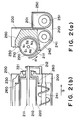
- Figure 2 shows an example of the developing device preventing the leakage of the developer from the end portion by the magnetic confining force.
- Figure 2 (a) is a sectional front view, and Figure 2, (b) is a sectional side view.
- FIG 2 designated by 200 is a developer container, and a shaft 211 of a magnet roller 210 is fixed to the developer container 200 by a fixing member 212. Therefore, the magnet roller 210 is stationary relative to the developer container 200.
- designate by 220 is a developing sleeve of a non-magnetic material containing the above-described magnet roller 210, and is supported rotatably relative to the developer container 200, by the bearings 221.
- the above-described magnet roller 210 has magnetized 5 magnetic poles (S1 pole, S2 pole, N1 pole, N2 pole, N3 pole), and the two component developer including the non-magnetic toner and magnetic carrier is taken up on the outside surface of developing sleeve 220 by the function of N3 pole (take-up pole).
- the taken up developer is transported to S2 pole (transportation pole) in accordance with the rotation of the developing sleeve 220 in the direction of an arrow R in Figure 2, and thereafter is coated as the thin layer on the outside surface of the developing sleeve 220 by the function of N1 pole (cutting pole) and the blade 230 as a regulation means for regulating a layer thickness of the developer.
- the developer coated as the thin layer develops a latent image formed on a unshown latent image bearing member adjacent the opposing position of S1 pole (developing pole).
- the non-magnetic toner is consumed by the developing action,and toner content is lowered.
- Such a developer is transported to N2 pole (take-in pole),and thereafter is not transported toward N3 pole from N2 pole by the function of the repelling magnetic field constituted by N3 pole and N2 pole.
- the developer exceeding a amount of carrying limit of the developer by N2 pole falls by the gravity in a first stirring chamber 240 in the developer container 200.
- the first screw 241 is provided, and the developer having fallen from the developing sleeve 220 and the developer remaining without being taken up by (take-up pole) N3 pole are transported in the direction of an arrow S in Figure 2 while being stirred by the rotation of the screw.
- the developer transported up to the end portion of the first stirring chamber 240 by the first screw 241 is transported into the second stirring chamber 250 through the opening at an end portion of a partition wall 201.
- an unshown toner content detection device and a toner supply device a proper amount of the non-magnetic toner is supplied, and thereafter is transported while being stirred by the rotation of the second screw 251, and is returned to the first stirring chamber through the opening at another end portion of the partition wall 201 to be used for the repeated developing action.
- a magnetic member 260 In order to prevent the leakage of the circulated developer at the neighborhood of opposite end portions in the thrust direction of the developing sleeve 220, there is provided a magnetic member 260. Referring to Figures 3 and 4,the mechanism of the leakage prevention of the developer by the magnetic member 260 will be described. The same reference numerals as in Figure 2 are assigned to the elements having the corresponding functions, and the detailed description thereof are omitted for the sake of simplicity.
- the strong magnetic confining force is produced between the magnetic member 260 and magnet roller 210 so that the developer is confined between the magnetic member 260 and developing sleeve 220 along the magnetic force line by the magnetic confining force as shown in Figure 4.
- the developer is not moved in accordance with the rotation, even if the developing sleeve 220 is rotated.
- the developer per se is confined by the strong magnetic confining force to form a wall between the magnetic member 260 and the developing sleeve 220 so that the leakage of the developer from developer container 200 at the neighborhood of opposite end portions in the thrust direction of the developing sleeve 220 is prevented.
- a principal function of the present invention is to provide a developing device wherein the uniform layer thickness of the developer is provided over the developing width on the developer carrying member.
- Another concern of the present invention is to provide a developing device wherein the length in the thrust direction of the developer carrying member is shortened.
- a developing apparatus comprising:
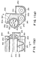
- Figure 1 is a sectional front view of a developing device according to an embodiment of the present invention.
- Figure 1 is a sectional side view of an apparatus of Figure 1, (a).
- Figure 2 is a sectional front view of the developing device as a background of the present invention.
- Figure 2 (b) is a sectional side view of the apparatus of Figure 2, (a).
- Figure 3 illustrate prevention of leakage of the developer.
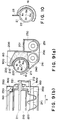
- Figure 9 is a sectional front view of the developing device according to another a embodiment of the present invention.
- Figure 9, (b) is a sectional side view of an apparatus of Figure 9, (a).
- Figure 10 is a partial sectional view of a developing device of another embodiment of the present invention.
- FIG. 1 a sectional view of a developing device according to an embodiment of the present invention is shown.
- the magnetic member 160 comprising the ferromagnetic member such as iron, cobalt, nickel is disposed opposed, with the gap from a surface of the developing sleeve, at the end portion in the thrust direction of the developing sleeve 220 comprising a non-magnetic metal such as aluminum, SUS as a developer carrying member for carrying the developer comprising a magnetic carrier and a non-magnetic toner.
- the magnetic member 160 is extended over approx. a half of the circumference in the circumferential direction of the developing sleeve 220.
- the magnetic member 160 In the thrust direction, the magnetic member 160 is positioned inwardly beyond the end surface of the magnet roller 210 producing the magnetic force for carrying the developer, and the magnetic force by the magnet roller 210 is concentrated, and the magnetic brush of the carrier is formed similarly to Figure 4, by the magnetic confining force so as to prevent the leakage of the developer.
- the magnetic member 160 includes a magnetic force reduction portion 160a having a large gap between the surface of developing sleeve 220 adjacent, in the circumferential direction of the developer carrying member, a blade 230 as a developer regulation member for regulating an amount of the developer on the developer carrying member and comprising non-magnetic metal such as SUS aluminum.
- the lengths of the developing sleeve 220 and the magnet roller 210 in the thrust direction are shortened, and therefore, the position of the magnetic member 160 is closer to the end portion of the magnet roller 210.
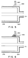
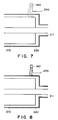
- Figures 7 and 8 shows magnetic force lines between the magnetic member 160 and the magnet roller 210 adjacent the blade 230, and a wall constituted by the developer between magnetic member 160 and the developing sleeve 220, with this structure.
- the width of the wall of the developer adjacent the blade is narrowed by decrease of the magnetic confining force, and the developer is hardly confined inside of the magnetic member 160 in the thrust direction. Therefore, the width of the developer in the thrust direction applied as the thin layer on the developing sleeve 220 can be assured, so that the entire area of the image having the maximum thrust direction width in the image forming apparatus using the present developing device can be developed.
- a point ( A in Figure 1) where the clearance between the magnetic material 160 and the developing sleeve 220 starts to widen is positioned downstream (direction of arrow R in Figure 1) with respect to the movement direction of the periphery of developing sleeve 220, of the point where the magnetic flux density between the pole N1 and the pole S2 is 0.
- the magnet roller has the magnetic pole N1 in the region opposed to the magnetic force reduction portion 160a, and particularly, the magnetic flux density of the region opposed to the magnetic force reduction portion 160a of the magnet roller is not zero.
- Figure 9 schematically shows arrangement of this embodiment.
- the same reference numerals as in Figure 1 are assigned to the elements having the corresponding functions, and the detailed description thereof are omitted for the sake of simplicity.
- Figure 9 designated by 900 is a magnet provided outside the magnetic material 160 in the thrust direction.
- the magnet is magnetized to S-pole at the side opposed to the developing sleeve 220 and N-pole at the opposite side therefrom.
- the component of magnetic flux density toward the center of the magnet roller 210 is 0,2T (200G) and is arcuated.
- the lifetime of the developing device of this embodiment can be extended to approx. 4 times the lifetime of the developing device of the first embodiment with the effect which is similar to the first embodiment maintained.
- the durability test conditions are the same as in the first embodiment.
- the present invention is applied to the developing device using two component developer including the non-magnetic toner and magnetic carrier.
- the present invention is not limited to the developing device using two component developer. It is effective also in the case that it is applied to a developing device using magnetic one component toner.
- the average particle size of the magnetic one component toner is smaller as compared with the magnetic carrier, e.g. substantially 10 ⁇ m, and therefore, in this embodiment, the clearance between the developing sleeve and magnetic material end portion is 2 mm, adjacent the blade, and 0.5 mm in the other portion.
- Figure 10 schematically shows arrangement of the major part of this embodiment.
- reference numeral 21 designates a magnet roller
- 22 designates a developing sleeve
- 23 designates a blade
- 16 designates a magnetic member
- the width of the developer wall constituted by the magnetic material provided in order to prevent the leakage of the developer toward the outside in the thrust direction can be narrowed as much as possible, and therefore, the entire width of the maximum image of the image forming apparatus in the thrust direction can be developed.
Landscapes
- Physics & Mathematics (AREA)
- General Physics & Mathematics (AREA)
- Dry Development In Electrophotography (AREA)
- Magnetic Brush Developing In Electrophotography (AREA)
Claims (14)
- Entwicklungsgerät mit:dadurch gekennzeichnet, daß die magnetische Begrenzungskraft für den Entwickler zwischen dem Magneten (210) und dem magnetischen Bauteil (160) in einer Umfangsrichtung des Entwicklerträgerbauteils (220) zum Einstellbauteil (230) hin schwächer ist.einem Entwicklerbehälter (200) zum Aufnehmen eines Entwicklers mit magnetischen Teilchen;einem zylindrischen, drehbaren, in einer Öffnung des Entwicklerbehälters vorgesehenen Entwicklerträgerbauteil (220) zum Tragen des Entwicklers;einem Magneten (210) im Entwicklerträgerbauteil (220);einem magnetischen Bauteil (160), das an einem Endabschnitt des Entwicklerträgerbauteils (220) vorgesehen ist und einer magnetischen Kraft des Magneten (210) unterworfen ist, um axialem Auslaufen von Entwickler entgegenzuwirken;wobei das magnetische Bauteil (160) mit einem radialen Spalt relativ zum Entwicklerträgerbauteil (220), entlang einem Teil des Umfangs des Entwicklerträgerbauteils (220) angeordnet ist; undeinem sich axial zum Entwicklerträgerbauteil (220) erstreckenden Einstellbauteil (230) zum Einstellen der Dicke einer Entwicklerschicht auf dem Entwicklerträgerbauteil (220);
- Gerät nach Patentanspruch 1, wobei die magnetische Begrenzungskraft außer in einer Nachbarschaft des Einstellbauteils (230) im wesentlichen konstant ist.
- Gerät nach Patentanspruch 1 oder 2, wobei der Spalt zwischen dem Entwicklerträgerbauteil (220) und dem magnetischen Bauteil (160) in der Umfangsrichtung zum Einstellbauteil (230) hin weiter ist.
- Gerät nach Patentanspruch 3, wobei der Spalt außer in einer Nachbarschaft des Einstellbauteils (230) im wesentlichen konstant ist.
- Gerät nach Patentanspruch 3, wobei in einem einem Abschnitt (160a) des magnetischen Bauteils (160) gegenüberliegenden, einen weiten Spalt aufweisenden und dem Einstellbauteil benachbarten Bereich des Magneten (210) die magnetische Flußdichte nicht Null ist.
- Gerät nach Patentanspruch 1, wobei das magnetische Bauteil (160) aus Eisen ist.
- Gerät nach Patentanspruch 6, wobei das Eisen mit Nickel überzogen ist.
- Gerät nach Patentanspruch 1, wobei eine Bürste aus den magnetischen Teilchen durch die magnetische Kraft des Magneten (210) zwischen dem Entwicklerträgerbauteil (220) und dem magnetischen Bauteil (160) ausgebildet ist, wobei die Bürste ein Verhindern eines Auslaufens des Entwicklers bewirkt.
- Gerät nach Patentanspruch 1, weiterhin mit einem Hilfsdichtungsbauteil (900) außerhalb des magnetischen Bauteils (160) in der axialen Richtung des Entwicklerträgerbauteils (220).
- Gerät nach Patentanspruch 9, wobei das Hilfsdichtungsbauteil (900) einen Magneten umfaßt.
- Gerät nach Patentanspruch 1, wobei sich der Magnet (210) entlang der axialen Richtung des Entwicklerträgerbauteils (220) erstreckt, und das Entwicklerträgerbauteil (220) magnetische Kraft zum Tragen des Entwicklers zur Entwicklung hervorbringt.
- Gerät nach Patentanspruch 11, wobei das magnetische Bauteil (160) jenseits eines Endabschnitts des Magneten (210) in der axialen Richtung des Entwicklerträgerbauteils (220) nach innen angeordnet ist.
- Gerät nach Patentanspruch 1, wobei der Entwickler unmagnetischen Toner enthält.
- Gerät nach Patentanspruch 3, wobei der Magnet (210) einen Magnetpol in einem einem Abschnitt des magnetischen Bauteils (160) gegenüberliegenden Bereich (160a) hat, der einen weiten Spalt hat und dem Einstellbauteil (230) benachbart ist.
Applications Claiming Priority (3)
| Application Number | Priority Date | Filing Date | Title |
|---|---|---|---|
| JP5591094 | 1994-03-25 | ||
| JP6055910A JP2960298B2 (ja) | 1994-03-25 | 1994-03-25 | 現像装置 |
| JP55910/94 | 1994-03-25 |
Publications (3)
| Publication Number | Publication Date |
|---|---|
| EP0674244A2 EP0674244A2 (de) | 1995-09-27 |
| EP0674244A3 EP0674244A3 (de) | 1996-12-27 |
| EP0674244B1 true EP0674244B1 (de) | 2000-05-31 |
Family
ID=13012277
Family Applications (1)
| Application Number | Title | Priority Date | Filing Date |
|---|---|---|---|
| EP95301985A Expired - Lifetime EP0674244B1 (de) | 1994-03-25 | 1995-03-24 | Entwicklungsgerät |
Country Status (6)
| Country | Link |
|---|---|
| US (1) | US5596392A (de) |
| EP (1) | EP0674244B1 (de) |
| JP (1) | JP2960298B2 (de) |
| KR (1) | KR0167073B1 (de) |
| CN (1) | CN1064143C (de) |
| DE (1) | DE69517230T2 (de) |
Families Citing this family (14)
| Publication number | Priority date | Publication date | Assignee | Title |
|---|---|---|---|---|
| JP3252090B2 (ja) * | 1996-07-10 | 2002-01-28 | キヤノン株式会社 | 現像装置 |
| US6385415B1 (en) * | 2000-05-18 | 2002-05-07 | Nexpress Solutions Llc | Development station for a reproduction apparatus |
| US20110036771A1 (en) | 2007-01-09 | 2011-02-17 | Steven Woodard | Ballasted anaerobic system and method for treating wastewater |
| US20100213123A1 (en) | 2007-01-09 | 2010-08-26 | Marston Peter G | Ballasted sequencing batch reactor system and method for treating wastewater |
| US20080164184A1 (en) * | 2007-01-09 | 2008-07-10 | Marston Peter G | Fluidic sealing system for a wet drum magnetic separator |
| AU2008205247B2 (en) | 2007-01-09 | 2010-07-01 | Evoqua Water Technologies Llc | A system and method for removing dissolved contaminants, particulate contaminants, and oil contaminants from industrial waste water |
| US8470172B2 (en) | 2007-01-09 | 2013-06-25 | Siemens Industry, Inc. | System for enhancing a wastewater treatment process |
| JP2010061064A (ja) | 2008-09-08 | 2010-03-18 | Ricoh Co Ltd | 現像剤担持体、現像装置、プロセスカートリッジ、及び、画像形成装置 |
| JP2012078548A (ja) * | 2010-10-01 | 2012-04-19 | Fuji Xerox Co Ltd | 現像装置および画像形成装置 |
| US20150030852A1 (en) | 2012-01-26 | 2015-01-29 | Ineos Europe Ag | Copolymers for wire and cable applications |
| AU2013274900A1 (en) | 2012-06-11 | 2014-11-27 | Evoqua Water Technologies Llc | Treatment using fixed film processes and ballasted settling |
| EP2900352A1 (de) | 2012-09-26 | 2015-08-05 | Evoqua Water Technologies LLC | Systems zur messung der konzentration einer magnetischen vorschaltvorrichtung in einer suspension |
| EP4006645B1 (de) * | 2018-02-02 | 2026-03-11 | Canon Kabushiki Kaisha | Verfahren zur befestigung einer regulierklinge und entwicklungsvorrichtung |
| EP4034506A4 (de) | 2019-11-08 | 2023-07-26 | Evoqua Water Technologies LLC | Beschleunigte absetzung von flocken nach der elektrokoagulation/einem elektrochemischen verfahren unter verwendung von flockung |
Family Cites Families (7)
| Publication number | Priority date | Publication date | Assignee | Title |
|---|---|---|---|---|
| US3982498A (en) * | 1973-11-19 | 1976-09-28 | Xerox Corporation | Development apparatus |
| JPS62143968U (de) * | 1986-03-05 | 1987-09-10 | ||
| DE69032352T2 (de) * | 1989-03-31 | 1998-10-08 | Canon Kk | Entwicklungsgerät |
| JPH02298974A (ja) * | 1989-05-12 | 1990-12-11 | Minolta Camera Co Ltd | 現像装置 |
| JP2892456B2 (ja) * | 1989-08-04 | 1999-05-17 | キヤノン株式会社 | 現像装置 |
| JP2899079B2 (ja) * | 1990-07-10 | 1999-06-02 | キヤノン株式会社 | 現像装置 |
| JPH04136965A (ja) * | 1990-09-28 | 1992-05-11 | Canon Inc | 現像装置 |
-
1994
- 1994-03-25 JP JP6055910A patent/JP2960298B2/ja not_active Expired - Fee Related
-
1995
- 1995-03-23 US US08/408,991 patent/US5596392A/en not_active Expired - Fee Related
- 1995-03-24 DE DE69517230T patent/DE69517230T2/de not_active Expired - Fee Related
- 1995-03-24 EP EP95301985A patent/EP0674244B1/de not_active Expired - Lifetime
- 1995-03-25 CN CN95103569.XA patent/CN1064143C/zh not_active Expired - Fee Related
- 1995-03-25 KR KR1019950006460A patent/KR0167073B1/ko not_active Expired - Fee Related
Also Published As
| Publication number | Publication date |
|---|---|
| JPH07261558A (ja) | 1995-10-13 |
| US5596392A (en) | 1997-01-21 |
| KR0167073B1 (ko) | 1999-03-20 |
| DE69517230D1 (de) | 2000-07-06 |
| CN1115425A (zh) | 1996-01-24 |
| EP0674244A2 (de) | 1995-09-27 |
| CN1064143C (zh) | 2001-04-04 |
| EP0674244A3 (de) | 1996-12-27 |
| DE69517230T2 (de) | 2000-10-19 |
| JP2960298B2 (ja) | 1999-10-06 |
Similar Documents
| Publication | Publication Date | Title |
|---|---|---|
| US5596392A (en) | Magnetic seal provided at an end portion of the developer carrying member | |
| US5287148A (en) | Magnetic seal for a developing apparatus | |
| US5070812A (en) | Electrostatic latent image developing apparatus | |
| JP3507294B2 (ja) | 現像装置 | |
| US6993274B2 (en) | Developing apparatus with plural developer bearing members for each image bearing member | |
| JP3252090B2 (ja) | 現像装置 | |
| US9436132B2 (en) | Development device | |
| GB2145943A (en) | Image development using non-magnetic developer | |
| JP2701162B2 (ja) | 現像装置 | |
| US6668147B2 (en) | Developing device, image forming device and process unit | |
| JP3472173B2 (ja) | 現像装置 | |
| JP3524315B2 (ja) | 現像装置 | |
| JP2005077540A (ja) | 現像装置 | |
| JP4528055B2 (ja) | 現像装置及びそれを用いた画像形成装置 | |
| EP0693715A2 (de) | Entwicklungsgerät | |
| JPH10282790A (ja) | 現像装置及びプロセスカートリッジ | |
| JP2001318534A (ja) | 現像装置 | |
| JP2000206788A (ja) | 現像装置 | |
| JP2001042642A (ja) | 現像装置 | |
| JP2024152199A (ja) | 現像装置 | |
| JPH0434576A (ja) | 現像装置 | |
| JP2005099486A (ja) | 現像装置 | |
| JPH0540399A (ja) | 現像装置 | |
| JP2000122415A (ja) | 現像装置 | |
| JP2012230332A (ja) | 現像装置の磁気シール構造 |
Legal Events
| Date | Code | Title | Description |
|---|---|---|---|
| PUAI | Public reference made under article 153(3) epc to a published international application that has entered the european phase |
Free format text: ORIGINAL CODE: 0009012 |
|
| AK | Designated contracting states |
Kind code of ref document: A2 Designated state(s): DE FR GB IT |
|
| PUAL | Search report despatched |
Free format text: ORIGINAL CODE: 0009013 |
|
| AK | Designated contracting states |
Kind code of ref document: A3 Designated state(s): DE FR GB IT |
|
| 17P | Request for examination filed |
Effective date: 19970507 |
|
| 17Q | First examination report despatched |
Effective date: 19970609 |
|
| GRAG | Despatch of communication of intention to grant |
Free format text: ORIGINAL CODE: EPIDOS AGRA |
|
| GRAG | Despatch of communication of intention to grant |
Free format text: ORIGINAL CODE: EPIDOS AGRA |
|
| GRAH | Despatch of communication of intention to grant a patent |
Free format text: ORIGINAL CODE: EPIDOS IGRA |
|
| GRAH | Despatch of communication of intention to grant a patent |
Free format text: ORIGINAL CODE: EPIDOS IGRA |
|
| GRAA | (expected) grant |
Free format text: ORIGINAL CODE: 0009210 |
|
| AK | Designated contracting states |
Kind code of ref document: B1 Designated state(s): DE FR GB IT |
|
| REF | Corresponds to: |
Ref document number: 69517230 Country of ref document: DE Date of ref document: 20000706 |
|
| ITF | It: translation for a ep patent filed | ||
| ET | Fr: translation filed | ||
| PLBE | No opposition filed within time limit |
Free format text: ORIGINAL CODE: 0009261 |
|
| STAA | Information on the status of an ep patent application or granted ep patent |
Free format text: STATUS: NO OPPOSITION FILED WITHIN TIME LIMIT |
|
| 26N | No opposition filed | ||
| REG | Reference to a national code |
Ref country code: GB Ref legal event code: IF02 |
|
| PGFP | Annual fee paid to national office [announced via postgrant information from national office to epo] |
Ref country code: GB Payment date: 20060317 Year of fee payment: 12 Ref country code: FR Payment date: 20060317 Year of fee payment: 12 |
|
| PGFP | Annual fee paid to national office [announced via postgrant information from national office to epo] |
Ref country code: IT Payment date: 20060331 Year of fee payment: 12 |
|
| PGFP | Annual fee paid to national office [announced via postgrant information from national office to epo] |
Ref country code: DE Payment date: 20060518 Year of fee payment: 12 |
|
| GBPC | Gb: european patent ceased through non-payment of renewal fee |
Effective date: 20070324 |
|
| REG | Reference to a national code |
Ref country code: FR Ref legal event code: ST Effective date: 20071130 |
|
| PG25 | Lapsed in a contracting state [announced via postgrant information from national office to epo] |
Ref country code: DE Free format text: LAPSE BECAUSE OF NON-PAYMENT OF DUE FEES Effective date: 20071002 |
|
| PG25 | Lapsed in a contracting state [announced via postgrant information from national office to epo] |
Ref country code: GB Free format text: LAPSE BECAUSE OF NON-PAYMENT OF DUE FEES Effective date: 20070324 |
|
| PG25 | Lapsed in a contracting state [announced via postgrant information from national office to epo] |
Ref country code: FR Free format text: LAPSE BECAUSE OF NON-PAYMENT OF DUE FEES Effective date: 20070402 |
|
| PG25 | Lapsed in a contracting state [announced via postgrant information from national office to epo] |
Ref country code: IT Free format text: LAPSE BECAUSE OF NON-PAYMENT OF DUE FEES Effective date: 20070324 |