EP0674073B1 - Beschlag für ein Fenster, eine Tür od. dgl. - Google Patents
Beschlag für ein Fenster, eine Tür od. dgl. Download PDFInfo
- Publication number
- EP0674073B1 EP0674073B1 EP95102482A EP95102482A EP0674073B1 EP 0674073 B1 EP0674073 B1 EP 0674073B1 EP 95102482 A EP95102482 A EP 95102482A EP 95102482 A EP95102482 A EP 95102482A EP 0674073 B1 EP0674073 B1 EP 0674073B1
- Authority
- EP
- European Patent Office
- Prior art keywords
- closing
- extension
- head
- fitting
- entrainment
- Prior art date
- Legal status (The legal status is an assumption and is not a legal conclusion. Google has not performed a legal analysis and makes no representation as to the accuracy of the status listed.)
- Expired - Lifetime
Links
- 229910000831 Steel Inorganic materials 0.000 claims description 2
- 239000010959 steel Substances 0.000 claims description 2
- 238000006073 displacement reaction Methods 0.000 claims 2
- 230000008878 coupling Effects 0.000 abstract description 4
- 238000010168 coupling process Methods 0.000 abstract description 4
- 238000005859 coupling reaction Methods 0.000 abstract description 4
- 230000004888 barrier function Effects 0.000 abstract description 2
- 238000012806 monitoring device Methods 0.000 abstract 1
- 210000003128 head Anatomy 0.000 description 11
- 210000001331 nose Anatomy 0.000 description 7
- 238000013459 approach Methods 0.000 description 4
- 230000005693 optoelectronics Effects 0.000 description 3
- 238000011156 evaluation Methods 0.000 description 2
- 230000003313 weakening effect Effects 0.000 description 2
- 229910000639 Spring steel Inorganic materials 0.000 description 1
- 239000008186 active pharmaceutical agent Substances 0.000 description 1
- 238000013461 design Methods 0.000 description 1
- 238000005516 engineering process Methods 0.000 description 1
- 238000003780 insertion Methods 0.000 description 1
- 230000037431 insertion Effects 0.000 description 1
- 238000004519 manufacturing process Methods 0.000 description 1
- 238000000034 method Methods 0.000 description 1
- 238000003825 pressing Methods 0.000 description 1
- 238000012545 processing Methods 0.000 description 1
- 230000000284 resting effect Effects 0.000 description 1
- 238000009420 retrofitting Methods 0.000 description 1
- 238000003860 storage Methods 0.000 description 1
- 239000012780 transparent material Substances 0.000 description 1
Images
Classifications
-
- E—FIXED CONSTRUCTIONS
- E05—LOCKS; KEYS; WINDOW OR DOOR FITTINGS; SAFES
- E05F—DEVICES FOR MOVING WINGS INTO OPEN OR CLOSED POSITION; CHECKS FOR WINGS; WING FITTINGS NOT OTHERWISE PROVIDED FOR, CONCERNED WITH THE FUNCTIONING OF THE WING
- E05F7/00—Accessories for wings not provided for in other groups of this subclass
- E05F7/08—Means for transmitting movements between vertical and horizontal sliding bars, rods, or cables
-
- E—FIXED CONSTRUCTIONS
- E05—LOCKS; KEYS; WINDOW OR DOOR FITTINGS; SAFES
- E05B—LOCKS; ACCESSORIES THEREFOR; HANDCUFFS
- E05B45/00—Alarm locks
- E05B45/06—Electric alarm locks
- E05B45/08—Electric alarm locks with contact making inside the lock or in the striking plate
- E05B45/12—Electric alarm locks with contact making inside the lock or in the striking plate by movement of the bolt
-
- E—FIXED CONSTRUCTIONS
- E05—LOCKS; KEYS; WINDOW OR DOOR FITTINGS; SAFES
- E05C—BOLTS OR FASTENING DEVICES FOR WINGS, SPECIALLY FOR DOORS OR WINDOWS
- E05C9/00—Arrangements of simultaneously actuated bolts or other securing devices at well-separated positions on the same wing
- E05C9/18—Details of fastening means or of fixed retaining means for the ends of bars
- E05C9/1825—Fastening means
- E05C9/1833—Fastening means performing sliding movements
- E05C9/185—Fastening means performing sliding movements parallel with actuating bar
-
- E—FIXED CONSTRUCTIONS
- E05—LOCKS; KEYS; WINDOW OR DOOR FITTINGS; SAFES
- E05Y—INDEXING SCHEME ASSOCIATED WITH SUBCLASSES E05D AND E05F, RELATING TO CONSTRUCTION ELEMENTS, ELECTRIC CONTROL, POWER SUPPLY, POWER SIGNAL OR TRANSMISSION, USER INTERFACES, MOUNTING OR COUPLING, DETAILS, ACCESSORIES, AUXILIARY OPERATIONS NOT OTHERWISE PROVIDED FOR, APPLICATION THEREOF
- E05Y2900/00—Application of doors, windows, wings or fittings thereof
- E05Y2900/10—Application of doors, windows, wings or fittings thereof for buildings or parts thereof
- E05Y2900/13—Type of wing
- E05Y2900/132—Doors
-
- E—FIXED CONSTRUCTIONS
- E05—LOCKS; KEYS; WINDOW OR DOOR FITTINGS; SAFES
- E05Y—INDEXING SCHEME ASSOCIATED WITH SUBCLASSES E05D AND E05F, RELATING TO CONSTRUCTION ELEMENTS, ELECTRIC CONTROL, POWER SUPPLY, POWER SIGNAL OR TRANSMISSION, USER INTERFACES, MOUNTING OR COUPLING, DETAILS, ACCESSORIES, AUXILIARY OPERATIONS NOT OTHERWISE PROVIDED FOR, APPLICATION THEREOF
- E05Y2900/00—Application of doors, windows, wings or fittings thereof
- E05Y2900/10—Application of doors, windows, wings or fittings thereof for buildings or parts thereof
- E05Y2900/13—Type of wing
- E05Y2900/148—Windows
Definitions
- the invention relates to a fitting for a window, a door or the like, consisting of a corner drive with a locking tongue equipped with light wedges a locking part works together with integrated evaluation logic and the corner drive on the inside of one angular faceplate a C-shaped guide channel helps to guide one of several spring steel strips existing, as a motion redirector acting spring assembly, that on further push rod parts is attached by means of a driver and the Closing tongue by means of clip fastening with a push rod part is connectable.
- optoelectronic Detector On locking and opening.
- the optoelectronics is in a commercial, in the fold one Window attached fitting housed.
- a Locked part In the lock-side, upper corner of the fixed frame is a Locked part, which with a closing opening Recording the locking tongue is provided.
- the transmitter and receiver On both sides of the The transmitter and receiver are located in the closing opening the locking part are arranged embedded and the under Interposition of a locking tongue, which several Contains light wedges made of transparent material.
- the working on the principle of the light barrier optoelectronic Detector is the closure of windows or Monitor doors.
- the invention has for its object a generic To create a fitting in which an exchange of Locking tongue even when the fitting is installed is made possible with a secure hold of the locking tongue on the Push rod part without additional processing steps are required at the corner deflection.
- the driver designed as a rivet for connecting the spring assembly to the push rod part receives an additional function, namely as a recording to serve for the opto locking tongue.
- the rivet is with the the recording forming means provided so that with the Connection of the driver with spring assembly and push rod part at the same time the holder for the locking tongue is created.
- An additional work and Assembly process for the inclusion of the locking tongue is required it no longer, also no additional weakening the cross section of the push rod part.
- the design of the driver at the same time as a recording for the Closing tongue allows the underhand grip of the noses one in front of the front of the push rod part or Spring packs lying and thus also with built-in corner deflection accessible level.
- the driver has at least a rectangular head in the area of the recording Cross-section in which a recess is rectangular Cross section is attached and the transverse to End faces of the head are in the direction of adjustment each with an undercut and the Closing tongue advantageously has a cross section the recess of the driver form-fittingly adapted Approach and at a distance from each in the direction of adjustment a resilient web, which at its free end with a Nose for springy engagement in the undercuts the head of the driver is provided.
- the recess the driver is used in particular for positive Inclusion of the approach of the locking tongue that is opposite the driver is centered and held.
- the backhand through the noses occurs outside the headboard of the driver and in each case in the direction of adjustment of the push rod part spaced from the approach and its inclusion on the head of the driver, so that the stop of the locking tongue on the driver is further improved.
- the undercuts noses under the head lie in front of the Front of the push rod part and the spring assembly and thus also in the assembled state of the corner drive for a Tool accessible without dismantling the corner drive.
- the Face plate of the corner drive an upstanding flange has to engage in a slot of the closing part is intended to achieve the correct assignment of the locking part to the locking tongue, it is advantageous that the flange on the inside of the vertical leg the faceplate of the corner drive is arranged, especially also by riveting.
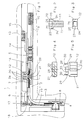
- a corner deflection 4 is arranged embedded, from an angular faceplate 5, behind arranged, C-shaped guide channel 6, in which as a motion redirector one of several flat steel strips existing spring assembly 7 is stored, which the vertical push rod part 8 with the horizontal Push rod part 9 connects positively.
- the Push rod parts 8, 9 are provided with coupling means 10 for attaching further poles to be connected.
- the connection of the spring assembly 7 with the horizontal Push rod part 9 takes place by means of a driver 11, which carries a locking tongue 12 which with a in the fold of the fixed frame 13 mounted closing part 14 cooperates.
- the closing part 14 is via elongated holes 15 held longitudinally on the fixed frame 13. It points a closing opening 16 for the locking tongue 12 and a slot 17 for cooperation with a flange 18, the on the inside of the vertical leg 19 of the Face plate 5 is riveted. In the area of the closing opening 16 are, externally not recognizable, the Evaluation unit and the sensor are concealed. Of the wing-side flange 18 occurs during a closing movement of the wing 3 in the slot 17 and causes one correct assignment of the locking opening 16 to the locking tongue 12 due to the longitudinally movable storage of Locking part 14 on the fixed frame 13.
- the driver 11 has a shaft 21 which one in Adjustment direction of the fitting rectangular head 22 owns.
- the head 22 is on the direction of adjustment transversely arranged end faces 23 each with an undercut 24 provided. Is embedded in the head 22 a recess 25 rectangular cross-section, the a slight insertion slope 26 is equipped.
- the shaft of the driver 11 is used as a rivet, whereby the rivet head 31 is arranged embedded in an impression 32 of the push rod part 9, as shown in FIG. 1.
- the locking tongue 12 with the lugs 30 on the Head 22 of the driver 11 put on and pressure on the Tongue 27 exerted, whereby the webs 29 slightly after spread out and down along the end faces 23 slide, the projection 28 engages in the recess 25.
- the underside 33 of the locking tongue 12 is open the head 22 of the driver 11 is resting, snap the lugs 30 resiliently under the undercuts 24. Die The locking tongue 12 is thus reliable on the driver 11 held and fixed.
- the point of engagement is when the sash 3 and with the corner drive 4 still accessible, as it is in front the spring assembly 5 and arranged by one for the adjustment the locking tongue 12 anyway necessary slot 34 of the faceplate 5 access for a Tool is possible.
Landscapes
- Engineering & Computer Science (AREA)
- Mechanical Engineering (AREA)
- Securing Of Glass Panes Or The Like (AREA)
- Dry Shavers And Clippers (AREA)
- Connection Of Plates (AREA)
- Power-Operated Mechanisms For Wings (AREA)
- Investigating Or Analysing Materials By Optical Means (AREA)
- Burglar Alarm Systems (AREA)
- Insertion Pins And Rivets (AREA)
Description
- Fig. 1
- einen Ausschnitt aus einer verschlußseitigen, oberen Ecke eines Fensters, das mit einem erfindungsgemäßen Beschlag ausgerüstet ist,
- Fig. 2
- den Mitnehmer aus Fig. 1 in vergrößertem Maßstab vor dessen Einbau,
- Fig. 3
- eine Draufsicht auf den Mitnehmer der Fig. 2,
- Fig. 4
- eine Draufsicht auf die Schließzunge der Fig. 1 in vergrößertem Maßstab und
- Fig. 5
- eine Seitenansicht der Schließzunge der Fig. 4.
Claims (4)
- Beschlag für ein Fenster, eine Tür od. dgl., bestehend aus einer Eckumlenkung (4) mit einer mit Lichtkeilen (20) ausgerüsteten Schließzunge (12), die mit einem Schließteil (14) mit integrierter Auswertlogik zusammenarbeitet und die Eckumlenkung (4) an der Innenseite einer winkelförmigen Stulpschiene (5) einen C-förmigen Führungskanal (6) trägt zur Führung eines aus mehreren Federstahlbändern bestehenden, als Bewegungsumlenkungsglied wirkenden Federpakets (7), das an weiterführenden Schubstangenteilen (8, 9) mittels eines Mitnehmers (11) befestigt ist und die Schließzunge (12) mittels Klipsbefestigung mit einem Schubstangenteil (9) verbindbar ist,
dadurch gekennzeichnet,
daß der Mitnehmer (11) gleichzeitig als Aufnahme für die Schließzunge (12) ausgebildet ist. - Beschlag nach Anspruch 1,
dadurch gekennzeichnet,
daß der Mitnehmer (11) zumindest im Bereich der Aufnahme einen Kopf (22) rechteckigen Querschnitts aufweist, in dem eine Ausnehmung (25) rechteckigen Querschnitts eingelassen angebracht ist und die quer zur Verstellrichtung liegenden Stirnflächen (23) des Kopfes (22) mit jeweils einer Hinterschneidung (24) versehen sind. - Beschlag nach einem der Ansprüche 1 und 2,
dadurch gekennzeichnet,
daß die Schließzunge (12) einen an den Querschnitt der Ausnehmung (25) des Mitnehmers (11) formschlüssig angepaßten Ansatz (28) und im Abstand davon in Verstellrichtung je einen federnden Steg (29) aufweist, der an seinem freien Ende mit einer Nase (30) zum federnden Eingreifen in die Hinterschneidungen (24) des Kopfes (22) des Mitnehmers (11) versehen ist. - Beschlag nach einem der Ansprüche 1 bis 3, bei dem das Schließteil (14) längsverschiebbar am zugeordneten Festrahmen (13) gelagert ist, die Stulpschiene (5) der Eckumlenkung (4) einen aufragenden Flansch (18) aufweist, der zum Eingriff in einen Schlitz (17) des Schließteils (14) bestimmt ist zur Erzielung der korrekten Zuordnung des Schließteils (14) zur Schließzunge (12),
dadurch gekennzeichnet,
daß der Flansch (18) an der Innenseite des senkrechten Schenkels (19) der Stulpschiene (5) der Eckumlenkung (4) angeordnet ist.
Applications Claiming Priority (2)
| Application Number | Priority Date | Filing Date | Title |
|---|---|---|---|
| DE9404964U DE9404964U1 (de) | 1994-03-23 | 1994-03-23 | Beschlag für ein Fenster, eine Tür o.dgl. |
| DE9404964U | 1994-03-23 |
Publications (2)
| Publication Number | Publication Date |
|---|---|
| EP0674073A1 EP0674073A1 (de) | 1995-09-27 |
| EP0674073B1 true EP0674073B1 (de) | 1998-02-04 |
Family
ID=6906425
Family Applications (1)
| Application Number | Title | Priority Date | Filing Date |
|---|---|---|---|
| EP95102482A Expired - Lifetime EP0674073B1 (de) | 1994-03-23 | 1995-02-22 | Beschlag für ein Fenster, eine Tür od. dgl. |
Country Status (3)
| Country | Link |
|---|---|
| EP (1) | EP0674073B1 (de) |
| AT (1) | ATE163060T1 (de) |
| DE (2) | DE9404964U1 (de) |
Families Citing this family (2)
| Publication number | Priority date | Publication date | Assignee | Title |
|---|---|---|---|---|
| DE20205634U1 (de) * | 2002-04-11 | 2003-08-21 | Mayer & Co., Salzburg | Beschlagaggregat für Flügel von Fenster, Türen u.dgl. |
| DE102008054672A1 (de) | 2008-12-15 | 2010-06-17 | Aug. Winkhaus Gmbh & Co. Kg | Kupplung zur Anbindung einer ein über zwei Schenkel geführtes Federband aufweisenden Eckumlenkung an einem längsverschieblichen Treibstangenabschnitt |
Family Cites Families (2)
| Publication number | Priority date | Publication date | Assignee | Title |
|---|---|---|---|---|
| AT370192B (de) * | 1977-12-22 | 1983-03-10 | Lapp Finze Ag | Verriegelungsvorrichtung, insbesondere fuer dreh-kipp-beschlaege |
| DE3915569A1 (de) * | 1989-05-12 | 1990-11-15 | Winkhaus Fa August | Fenstersystem fuer ein gebaeude |
-
1994
- 1994-03-23 DE DE9404964U patent/DE9404964U1/de not_active Expired - Lifetime
-
1995
- 1995-02-22 AT AT95102482T patent/ATE163060T1/de not_active IP Right Cessation
- 1995-02-22 DE DE59501390T patent/DE59501390D1/de not_active Expired - Fee Related
- 1995-02-22 EP EP95102482A patent/EP0674073B1/de not_active Expired - Lifetime
Also Published As
| Publication number | Publication date |
|---|---|
| EP0674073A1 (de) | 1995-09-27 |
| ATE163060T1 (de) | 1998-02-15 |
| DE9404964U1 (de) | 1994-05-19 |
| DE59501390D1 (de) | 1998-03-12 |
Similar Documents
| Publication | Publication Date | Title |
|---|---|---|
| EP0822310B1 (de) | Schiebetüranlage | |
| EP0718456A1 (de) | Fenster, Tür, od. ähnlicher Öffnungsverschluss | |
| EP0969176A2 (de) | Rahmenloser Glasflügel als beweglich gelagerter oder ortsfester Flügel einer Tür, eines Fensters oder einer Fassade oder Glaswand | |
| EP0433623B1 (de) | Verriegelungsvorrichtung für ein Fenster, eine Tür od.dgl. | |
| DE202022104654U1 (de) | Profilanordnung eines Fensters oder einer Tür mit einem Flügelprofil, insbesondere einem Schiebeflügelprofil | |
| EP1580375A2 (de) | Schliessblech für Fenster oder Fenstertüren | |
| DD291117A5 (de) | Untere abdichtung einer schwellenlosen tuer | |
| EP0556442B1 (de) | Treibstangenbeschlag für Fenster, Türen od. dgl. | |
| EP0674073A1 (de) | Beschlag für ein Fenster, eine Tür od. dgl. | |
| EP0687786B1 (de) | Schiebetürbeschlag | |
| DE19806727A1 (de) | Fenster- oder Türverschluß | |
| DE19931719A1 (de) | Beschlagsystem für Flügelrahmen eines Drehkippfensters oder einer Drehkipptür und Stulpeneinsatz- und Treibstangenkoppelkörper hierfür | |
| DE19814498B4 (de) | Stulpschienenbeschlag | |
| DE3150029A1 (de) | Drehkippbeschlag fuer fenster und tueren od.dgl. | |
| DE19717959A1 (de) | Vorrichtung zum Öffnen, Schließen oder Dämpfen eines Flügels einer Tür, eines Fensters oder dergleichen | |
| EP1580374B1 (de) | Fenster oder Tür | |
| DE19709283A1 (de) | Kantengetriebe | |
| DE102022102457A1 (de) | Adapterbeschlag für ein fenster oder eine tür zur realisierung einer sparlüftungsfunktion | |
| EP0573820B1 (de) | Beschlag für einen verschiebbaren Flügel von Fenstern, Türen od. dgl. | |
| EP1854949A2 (de) | Gleitschiene für einen Türschließer | |
| DE29600891U1 (de) | Sicherungseinrichtung | |
| DE19857384C2 (de) | Befestigungsmittel zum Verbinden eines Flügelrahmens mit einem Blendrahmen zu einem nicht öffenbaren Fenster | |
| DE4203909C2 (de) | Kippriegelvorrichtung | |
| DE4240503A1 (de) | Kunststoff- oder Aluminiumfenster mit einem Rahmen aus extrudierten oder gepreßten Hohlprofilen | |
| DE10229228A1 (de) | Tür-oder Fensterflügelanordnung |
Legal Events
| Date | Code | Title | Description |
|---|---|---|---|
| PUAI | Public reference made under article 153(3) epc to a published international application that has entered the european phase |
Free format text: ORIGINAL CODE: 0009012 |
|
| AK | Designated contracting states |
Kind code of ref document: A1 Designated state(s): AT DE FR IT |
|
| 17P | Request for examination filed |
Effective date: 19960130 |
|
| GRAG | Despatch of communication of intention to grant |
Free format text: ORIGINAL CODE: EPIDOS AGRA |
|
| GRAG | Despatch of communication of intention to grant |
Free format text: ORIGINAL CODE: EPIDOS AGRA |
|
| GRAH | Despatch of communication of intention to grant a patent |
Free format text: ORIGINAL CODE: EPIDOS IGRA |
|
| 17Q | First examination report despatched |
Effective date: 19970728 |
|
| GRAH | Despatch of communication of intention to grant a patent |
Free format text: ORIGINAL CODE: EPIDOS IGRA |
|
| GRAA | (expected) grant |
Free format text: ORIGINAL CODE: 0009210 |
|
| AK | Designated contracting states |
Kind code of ref document: B1 Designated state(s): AT DE FR IT |
|
| REF | Corresponds to: |
Ref document number: 163060 Country of ref document: AT Date of ref document: 19980215 Kind code of ref document: T |
|
| REF | Corresponds to: |
Ref document number: 59501390 Country of ref document: DE Date of ref document: 19980312 |
|
| ET | Fr: translation filed | ||
| ITF | It: translation for a ep patent filed | ||
| PLBE | No opposition filed within time limit |
Free format text: ORIGINAL CODE: 0009261 |
|
| STAA | Information on the status of an ep patent application or granted ep patent |
Free format text: STATUS: NO OPPOSITION FILED WITHIN TIME LIMIT |
|
| 26N | No opposition filed | ||
| PGFP | Annual fee paid to national office [announced via postgrant information from national office to epo] |
Ref country code: FR Payment date: 20010112 Year of fee payment: 7 |
|
| PGFP | Annual fee paid to national office [announced via postgrant information from national office to epo] |
Ref country code: DE Payment date: 20010116 Year of fee payment: 7 |
|
| PGFP | Annual fee paid to national office [announced via postgrant information from national office to epo] |
Ref country code: AT Payment date: 20010214 Year of fee payment: 7 |
|
| PG25 | Lapsed in a contracting state [announced via postgrant information from national office to epo] |
Ref country code: AT Free format text: LAPSE BECAUSE OF NON-PAYMENT OF DUE FEES Effective date: 20020222 |
|
| PG25 | Lapsed in a contracting state [announced via postgrant information from national office to epo] |
Ref country code: DE Free format text: LAPSE BECAUSE OF NON-PAYMENT OF DUE FEES Effective date: 20020903 |
|
| PG25 | Lapsed in a contracting state [announced via postgrant information from national office to epo] |
Ref country code: FR Free format text: LAPSE BECAUSE OF NON-PAYMENT OF DUE FEES Effective date: 20021031 |
|
| REG | Reference to a national code |
Ref country code: FR Ref legal event code: ST |
|
| PG25 | Lapsed in a contracting state [announced via postgrant information from national office to epo] |
Ref country code: IT Free format text: LAPSE BECAUSE OF NON-PAYMENT OF DUE FEES;WARNING: LAPSES OF ITALIAN PATENTS WITH EFFECTIVE DATE BEFORE 2007 MAY HAVE OCCURRED AT ANY TIME BEFORE 2007. THE CORRECT EFFECTIVE DATE MAY BE DIFFERENT FROM THE ONE RECORDED. Effective date: 20050222 |