EP0673780A2 - Bildempfangsschicht für thermische Übertragung - Google Patents
Bildempfangsschicht für thermische Übertragung Download PDFInfo
- Publication number
- EP0673780A2 EP0673780A2 EP19950109212 EP95109212A EP0673780A2 EP 0673780 A2 EP0673780 A2 EP 0673780A2 EP 19950109212 EP19950109212 EP 19950109212 EP 95109212 A EP95109212 A EP 95109212A EP 0673780 A2 EP0673780 A2 EP 0673780A2
- Authority
- EP
- European Patent Office
- Prior art keywords
- heat transfer
- transfer image
- receiving sheet
- sheet
- dye
- Prior art date
- Legal status (The legal status is an assumption and is not a legal conclusion. Google has not performed a legal analysis and makes no representation as to the accuracy of the status listed.)
- Granted
Links
Images

Classifications
-
- B—PERFORMING OPERATIONS; TRANSPORTING
- B41—PRINTING; LINING MACHINES; TYPEWRITERS; STAMPS
- B41M—PRINTING, DUPLICATING, MARKING, OR COPYING PROCESSES; COLOUR PRINTING
- B41M5/00—Duplicating or marking methods; Sheet materials for use therein
- B41M5/50—Recording sheets characterised by the coating used to improve ink, dye or pigment receptivity, e.g. for ink-jet or thermal dye transfer recording
- B41M5/52—Macromolecular coatings
-
- B—PERFORMING OPERATIONS; TRANSPORTING
- B41—PRINTING; LINING MACHINES; TYPEWRITERS; STAMPS
- B41M—PRINTING, DUPLICATING, MARKING, OR COPYING PROCESSES; COLOUR PRINTING
- B41M5/00—Duplicating or marking methods; Sheet materials for use therein
- B41M5/26—Thermography ; Marking by high energetic means, e.g. laser otherwise than by burning, and characterised by the material used
- B41M5/40—Thermography ; Marking by high energetic means, e.g. laser otherwise than by burning, and characterised by the material used characterised by the base backcoat, intermediate, or covering layers, e.g. for thermal transfer dye-donor or dye-receiver sheets; Heat, radiation filtering or absorbing means or layers; combined with other image registration layers or compositions; Special originals for reproduction by thermography
- B41M5/41—Base layers supports or substrates
-
- B—PERFORMING OPERATIONS; TRANSPORTING
- B41—PRINTING; LINING MACHINES; TYPEWRITERS; STAMPS
- B41M—PRINTING, DUPLICATING, MARKING, OR COPYING PROCESSES; COLOUR PRINTING
- B41M5/00—Duplicating or marking methods; Sheet materials for use therein
- B41M5/26—Thermography ; Marking by high energetic means, e.g. laser otherwise than by burning, and characterised by the material used
- B41M5/40—Thermography ; Marking by high energetic means, e.g. laser otherwise than by burning, and characterised by the material used characterised by the base backcoat, intermediate, or covering layers, e.g. for thermal transfer dye-donor or dye-receiver sheets; Heat, radiation filtering or absorbing means or layers; combined with other image registration layers or compositions; Special originals for reproduction by thermography
- B41M5/42—Intermediate, backcoat, or covering layers
-
- B—PERFORMING OPERATIONS; TRANSPORTING
- B41—PRINTING; LINING MACHINES; TYPEWRITERS; STAMPS
- B41M—PRINTING, DUPLICATING, MARKING, OR COPYING PROCESSES; COLOUR PRINTING
- B41M2205/00—Printing methods or features related to printing methods; Location or type of the layers
- B41M2205/02—Dye diffusion thermal transfer printing (D2T2)
-
- B—PERFORMING OPERATIONS; TRANSPORTING
- B41—PRINTING; LINING MACHINES; TYPEWRITERS; STAMPS
- B41M—PRINTING, DUPLICATING, MARKING, OR COPYING PROCESSES; COLOUR PRINTING
- B41M2205/00—Printing methods or features related to printing methods; Location or type of the layers
- B41M2205/06—Printing methods or features related to printing methods; Location or type of the layers relating to melt (thermal) mass transfer
-
- B—PERFORMING OPERATIONS; TRANSPORTING
- B41—PRINTING; LINING MACHINES; TYPEWRITERS; STAMPS
- B41M—PRINTING, DUPLICATING, MARKING, OR COPYING PROCESSES; COLOUR PRINTING
- B41M2205/00—Printing methods or features related to printing methods; Location or type of the layers
- B41M2205/36—Backcoats; Back layers
-
- B—PERFORMING OPERATIONS; TRANSPORTING
- B41—PRINTING; LINING MACHINES; TYPEWRITERS; STAMPS
- B41M—PRINTING, DUPLICATING, MARKING, OR COPYING PROCESSES; COLOUR PRINTING
- B41M5/00—Duplicating or marking methods; Sheet materials for use therein
- B41M5/26—Thermography ; Marking by high energetic means, e.g. laser otherwise than by burning, and characterised by the material used
- B41M5/40—Thermography ; Marking by high energetic means, e.g. laser otherwise than by burning, and characterised by the material used characterised by the base backcoat, intermediate, or covering layers, e.g. for thermal transfer dye-donor or dye-receiver sheets; Heat, radiation filtering or absorbing means or layers; combined with other image registration layers or compositions; Special originals for reproduction by thermography
- B41M5/42—Intermediate, backcoat, or covering layers
- B41M5/426—Intermediate, backcoat, or covering layers characterised by inorganic compounds, e.g. metals, metal salts, metal complexes
-
- B—PERFORMING OPERATIONS; TRANSPORTING
- B41—PRINTING; LINING MACHINES; TYPEWRITERS; STAMPS
- B41M—PRINTING, DUPLICATING, MARKING, OR COPYING PROCESSES; COLOUR PRINTING
- B41M5/00—Duplicating or marking methods; Sheet materials for use therein
- B41M5/26—Thermography ; Marking by high energetic means, e.g. laser otherwise than by burning, and characterised by the material used
- B41M5/40—Thermography ; Marking by high energetic means, e.g. laser otherwise than by burning, and characterised by the material used characterised by the base backcoat, intermediate, or covering layers, e.g. for thermal transfer dye-donor or dye-receiver sheets; Heat, radiation filtering or absorbing means or layers; combined with other image registration layers or compositions; Special originals for reproduction by thermography
- B41M5/42—Intermediate, backcoat, or covering layers
- B41M5/44—Intermediate, backcoat, or covering layers characterised by the macromolecular compounds
- B41M5/446—Fluorine-containing polymers
-
- B—PERFORMING OPERATIONS; TRANSPORTING
- B41—PRINTING; LINING MACHINES; TYPEWRITERS; STAMPS
- B41M—PRINTING, DUPLICATING, MARKING, OR COPYING PROCESSES; COLOUR PRINTING
- B41M5/00—Duplicating or marking methods; Sheet materials for use therein
- B41M5/50—Recording sheets characterised by the coating used to improve ink, dye or pigment receptivity, e.g. for ink-jet or thermal dye transfer recording
- B41M5/52—Macromolecular coatings
- B41M5/5218—Macromolecular coatings characterised by inorganic additives, e.g. pigments, clays
-
- B—PERFORMING OPERATIONS; TRANSPORTING
- B41—PRINTING; LINING MACHINES; TYPEWRITERS; STAMPS
- B41M—PRINTING, DUPLICATING, MARKING, OR COPYING PROCESSES; COLOUR PRINTING
- B41M5/00—Duplicating or marking methods; Sheet materials for use therein
- B41M5/50—Recording sheets characterised by the coating used to improve ink, dye or pigment receptivity, e.g. for ink-jet or thermal dye transfer recording
- B41M5/52—Macromolecular coatings
- B41M5/5227—Macromolecular coatings characterised by organic non-macromolecular additives, e.g. UV-absorbers, plasticisers, surfactants
-
- B—PERFORMING OPERATIONS; TRANSPORTING
- B41—PRINTING; LINING MACHINES; TYPEWRITERS; STAMPS
- B41M—PRINTING, DUPLICATING, MARKING, OR COPYING PROCESSES; COLOUR PRINTING
- B41M5/00—Duplicating or marking methods; Sheet materials for use therein
- B41M5/50—Recording sheets characterised by the coating used to improve ink, dye or pigment receptivity, e.g. for ink-jet or thermal dye transfer recording
- B41M5/52—Macromolecular coatings
- B41M5/5245—Macromolecular coatings characterised by the use of polymers containing cationic or anionic groups, e.g. mordants
-
- B—PERFORMING OPERATIONS; TRANSPORTING
- B41—PRINTING; LINING MACHINES; TYPEWRITERS; STAMPS
- B41M—PRINTING, DUPLICATING, MARKING, OR COPYING PROCESSES; COLOUR PRINTING
- B41M5/00—Duplicating or marking methods; Sheet materials for use therein
- B41M5/50—Recording sheets characterised by the coating used to improve ink, dye or pigment receptivity, e.g. for ink-jet or thermal dye transfer recording
- B41M5/52—Macromolecular coatings
- B41M5/5254—Macromolecular coatings characterised by the use of polymers obtained by reactions only involving carbon-to-carbon unsaturated bonds, e.g. vinyl polymers
-
- B—PERFORMING OPERATIONS; TRANSPORTING
- B41—PRINTING; LINING MACHINES; TYPEWRITERS; STAMPS
- B41M—PRINTING, DUPLICATING, MARKING, OR COPYING PROCESSES; COLOUR PRINTING
- B41M5/00—Duplicating or marking methods; Sheet materials for use therein
- B41M5/50—Recording sheets characterised by the coating used to improve ink, dye or pigment receptivity, e.g. for ink-jet or thermal dye transfer recording
- B41M5/52—Macromolecular coatings
- B41M5/5263—Macromolecular coatings characterised by the use of polymers obtained otherwise than by reactions only involving carbon-to-carbon unsaturated bonds
- B41M5/5272—Polyesters; Polycarbonates
-
- Y—GENERAL TAGGING OF NEW TECHNOLOGICAL DEVELOPMENTS; GENERAL TAGGING OF CROSS-SECTIONAL TECHNOLOGIES SPANNING OVER SEVERAL SECTIONS OF THE IPC; TECHNICAL SUBJECTS COVERED BY FORMER USPC CROSS-REFERENCE ART COLLECTIONS [XRACs] AND DIGESTS
- Y10—TECHNICAL SUBJECTS COVERED BY FORMER USPC
- Y10S—TECHNICAL SUBJECTS COVERED BY FORMER USPC CROSS-REFERENCE ART COLLECTIONS [XRACs] AND DIGESTS
- Y10S428/00—Stock material or miscellaneous articles
- Y10S428/913—Material designed to be responsive to temperature, light, moisture
-
- Y—GENERAL TAGGING OF NEW TECHNOLOGICAL DEVELOPMENTS; GENERAL TAGGING OF CROSS-SECTIONAL TECHNOLOGIES SPANNING OVER SEVERAL SECTIONS OF THE IPC; TECHNICAL SUBJECTS COVERED BY FORMER USPC CROSS-REFERENCE ART COLLECTIONS [XRACs] AND DIGESTS
- Y10—TECHNICAL SUBJECTS COVERED BY FORMER USPC
- Y10S—TECHNICAL SUBJECTS COVERED BY FORMER USPC CROSS-REFERENCE ART COLLECTIONS [XRACs] AND DIGESTS
- Y10S428/00—Stock material or miscellaneous articles
- Y10S428/914—Transfer or decalcomania
-
- Y—GENERAL TAGGING OF NEW TECHNOLOGICAL DEVELOPMENTS; GENERAL TAGGING OF CROSS-SECTIONAL TECHNOLOGIES SPANNING OVER SEVERAL SECTIONS OF THE IPC; TECHNICAL SUBJECTS COVERED BY FORMER USPC CROSS-REFERENCE ART COLLECTIONS [XRACs] AND DIGESTS
- Y10—TECHNICAL SUBJECTS COVERED BY FORMER USPC
- Y10T—TECHNICAL SUBJECTS COVERED BY FORMER US CLASSIFICATION
- Y10T428/00—Stock material or miscellaneous articles
- Y10T428/31504—Composite [nonstructural laminate]
- Y10T428/3154—Of fluorinated addition polymer from unsaturated monomers
-
- Y—GENERAL TAGGING OF NEW TECHNOLOGICAL DEVELOPMENTS; GENERAL TAGGING OF CROSS-SECTIONAL TECHNOLOGIES SPANNING OVER SEVERAL SECTIONS OF THE IPC; TECHNICAL SUBJECTS COVERED BY FORMER USPC CROSS-REFERENCE ART COLLECTIONS [XRACs] AND DIGESTS
- Y10—TECHNICAL SUBJECTS COVERED BY FORMER USPC
- Y10T—TECHNICAL SUBJECTS COVERED BY FORMER US CLASSIFICATION
- Y10T428/00—Stock material or miscellaneous articles
- Y10T428/31504—Composite [nonstructural laminate]
- Y10T428/31652—Of asbestos
- Y10T428/31663—As siloxane, silicone or silane
Definitions
- the present invention relates to a heat transfer image-receiving sheet used in combination with a heat transfer sheet.
- a sublimation type of transfer system wherein a sublimable dye as a recording material is carried on a substrate sheet such as paper or a plastic film to make a heat transfer sheet, which is in turn overlaid on a heat transfer sheet dyeable with a sublimable dye, for instance, a heat transfer sheet comprising paper or a plastic film having a dye-receiving layer on its surface to make various full-color image thereon.
- the thermal head of a printer is used as heating means to transfer three-, four- or more-color dots onto the heat transfer image-receiving sheet by quick heating, thereby reproducing full-color images of manuscripts with said multicolor dots.
- the heat transfer image-receiving sheet used with such a sublimation type of heat transfer system as mentioned above is required to form a light reflecting image, as is the case with generally available prints or photographs, it is formed of an opaque substrate sheet such as a paper or synthetic paper sheet having on its surface a dye-receiving layer of a resin capable of being well-dyed with a dye.
- an opaque substrate sheet such as a paper or synthetic paper sheet having on its surface a dye-receiving layer of a resin capable of being well-dyed with a dye.
- OHP overhead projector
- the curling problem may be solved by forming a curlproof layer of a suitable resin on the back side of the heat transfer image-receiving sheet.
- a sheet feeder unit of the printer if such image-receiving sheets, placed one upon another, are fed through a sheet feeder unit of the printer, then the multiple feeding problem arises, because the coefficient of friction between the curlproof layer of the sheet above and the dye-receiving layer of the sheet below is high.
- This problem may be solved to some extent by adding a slip agent such as silicone oil to the curlproof layer.
- silicone oil tends to bleed through the image-receiving sheet or otherwise pass into the dye-receiving sheet below, posing various problems.
- images obtained with the heat transfer techniques excel in clearness, color reproducibility and other factors and so are of high quality comparable to that of conventional photographic or printed images, because the colorant used is a dye.
- a transmission type of image of improved clearness and high resolution can advantageously be projected.
- the image-receiving sheet for OHPs is provided with a detection mark for positioning.
- conventional detection marks have been formed of black, white or silver inks, all having high shielding properties. As a result, an image projected on a screen becomes dull, since the detection mark throws a black shadow on the screen.
- OHP film is so curled by the heat generated from a projector's light source that it is troublesome to handle and the projected image is distorted.
- a heat transfer image-receiving sheet including a substrate sheet, a dye-receiving layer formed on the surface side of the substrate sheet and a slip layer formed on the back side of the substrate sheet, characterized in that said slip layer comprises a graft copolymer containing at least one of releasable segments selected from the groups consisting of polysiloxane, carbon fluoride and long-chain alkyl segments, said segment or segments being grafted on the main chain of said graft copolymer.
- the slip layer of a heat transfer image-receiving sheet is formed of such a specific releasable graft copolymer as referred to above, thereby making it possible to improve the in-printer slip properties, blocking resistance and curlproofness thereof and form a high-quality image without causing any printing trouble.
- a transparent type of heat transfer image-receiving sheet including a transparent substrate sheet having a transparent dye-receiving layer on the surface side, characterized in that said image-receiving sheet is provided on a part of at least one side with a light transmitting, colored detection mark.
- a transparent type of heat transfer image-receiving sheet for OHPs, etc. is provided on a part of at least one side with a light transmitting, colored detection mark, whereby said detection mark is projected in colors on a screen to prevent the projected image from becoming dull.
- Figs. 1 and 2 each are a sectional view of the heat transfer image-receiving sheet which embodies this invention.
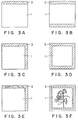
- Figs. 3A, 3B, 3C, 3D, 3E and 3F each are a plan view of the heat transfer image-receiving sheet which embodies this invention.
- the heat transfer image-receiving sheet according to the first aspect of this invention includes a substrate sheet, a dye-receiving layer formed on the surface side of the substrate sheet and a slip layer formed on the back side of the substrate sheet.
- the substrate sheets used in the present invention use may be made of various types of paper such as synthetic paper (based on polyolefin, polystyrene, etc.), fine paper, art paper, coated paper, cast coated paper, wall paper, backing paper, synthetic resin or emulsion impregnated paper, synthetic rubber latex impregnated paper, synthetic resin intercalated paper, paper board and cellulose fiber paper; and various kinds of plastic films or sheets based on, e.g., polyolefin, polyvinyl chloride, polyethylene terephthalate, polystyrene, polymethacrylate and polycarbonate.
- synthetic paper based on polyolefin, polystyrene, etc.
- fine paper art paper
- coated paper coated paper
- cast coated paper cast coated paper
- wall paper backing paper
- synthetic resin or emulsion impregnated paper synthetic rubber latex impregnated paper
- synthetic resin intercalated paper synthetic resin intercalated paper
- paper board and cellulose fiber paper various kinds of plastic films or sheets
- Use may also be made of white, opaque films or foamed sheets obtained from such synthetic resins to which white pigments and fillers are added.
- These substrate sheets may be laminated together in any desired combination.
- the substrate sheet or sheets may have any desired thickness, for instance, a thickness of generally about 10 to 300 ⁇ m. If required, plasticizers, etc. may be added to the plastic films to regulate their rigidity.
- a polyethylene terephthalate film having a thickness of about 50-200 ⁇ m is preferably used.
- the dye-receiving layer to be provided on the surface side of the substrate sheet is to receive a sublimable dye coming from a heat transfer sheet and maintain the resulting image.
- the resins used to form the dye-receiving layer may include polyolefinic resins such as polypropylene; halogenated vinyl resins such as polyvinyl chloride and polyvinylidene chloride; vinylic resins such as polyvinyl acetate and polyacryl ester; polyester resins such as polyethylene terephthalate and polybutylene terephthalate; polystyrene type resins; polyamide type resins; copolymeric resins such as copolymers of olefins such as ethylene and propylene with other vinyl monomers; ionomers; cellulosic resins such as cellulose diacetate; and polycarbonate. Particular preference is given to vinylic resins and polyester resins.
- the dye-receiving layer of the heat transfer image-receiving sheet according to the first aspect of this invention may be formed by coating on at least one major side of the substrate sheet a solution or dispersion in which the binder resin is dissolved or dispersed in a suitable organic solvent or water together with the required additives such as release agents, antioxidants and UV absorbers by suitable means such as gravure printing, screen printing or reverse roll coating using a gravure, followed by drying.
- the dye-receiving layer may be formed by adding to the resin pigments or fillers such as titanium oxide, zinc oxide, kaolin, clay, calcium carbonate and finely divided silica, thereby improving its whiteness and so making the clearness of the resulting image much higher.
- the dye-receiving layer may be made substantially transparent.
- the thus formed dye-receiving layer may have any desired thickness, but is generally 1 to 50 ⁇ m in thickness.
- a dye-receiving layer should preferably be in a continuous film form, but may be formed into a discontinuous film with the use of a resin emulsion or dispersion.
- the slip layer by which the 1st aspect of this invention is primarily characterized, is provided to prevent curling of the heat transfer image-receiving sheet by the heat of a thermal head during heat transfer and improve the blocking resistance and slip properties of the heat transfer image-receiving sheets when placed one upon another.
- a specific graft copolymer that is, a graft copolymer having at least one of releasable segments selected from polysiloxane, carbon fluoride and long-chain alkyl segments, said segment or segments being grafted on the main chain of said graft copolymer, is formed on the back side of the substrate sheet.
- main chain-forming polymers use may be made of those having a reactive functional group and known in the art. More illustratively, preference is given to cellulosic resins such as ethyl cellulose, hydroxyethyl cellulose, ethylhydroxy cellulose, hydroxypropyl cellulose, methyl cellulose, cellulose acetate and cellulose acetate butyrate; acrylic resins; polyvinylic resins such as polyvinyl alcohol, polyvinyl acetate, polyvinyl butyral, polyvinyl acetal, polyvinyl pyrrolidone and polyacrylamide; polyamide type resins; polyurethane type resins; and polyester type resins. The most preference, however, is given to the acrylic, vinylic, polyester type, polyurethane type, polyamide type or cellulosic resins in consideration of curlproofness.
- cellulosic resins such as ethyl cellulose, hydroxyethyl cellulose, ethylhydroxy cellulose,
- the releasable graft copolymers used in this invention may be synthesized in various manners. According to one preferable method, the main chain is formed, followed by the reaction of a functional group present in it with a releasable compound having a functional group reactive therewith.
- n stands for an integer of about 1-500.
- Higher fatty acids such as lauric, myristic, palmitic, stearic, oleic and linoleic acids or their acid halogenides; higher alcohols such as nonyl, capryl, lauryl, myristyl, cetyl, stearyl, oleyl, linoleyl and ricinoleyl alcohols; higher aldehydes such as caprin, laurin, myristin and stearin aldehydes; and higher amines such as decylamine, laurylamine and cetylamine.
- the aforesaid functional releasable compound is permitted to react with a vinylic compound having a functional group reactive with a functional group thereof to prepare a releasable segment-containing monomer.
- This monomer is copolymerized with various vinyl monomers, thereby obtaining desired graft copolymers.
- a mercapto compound such as Compound (7) or the aforesaid releasable vinyl compound is added to a polymer having an unsaturated double bond in its main chain, such as an unsaturated polyester or a copolymer of vinyl monomer with a diene compound such as butadiene for grafting.
- graft copolymers prepared by other methods or commercially available graft copolymers of the same type may be used in the first aspect of this invention.
- the releasable segment or segments should account for 3 to 60% by weight of the graft copolymer. In too small an amount no satisfactory blocking resistance and slip properties are obtainable, whereas in too large an amount a problem arises in connection with the adhesion of the slip layer to the substrate sheet.
- releasable graft copolymers some have a high content of the releasable segment and make the adhesion of the slip layer to the substrate sheet insufficient due to their increased releasability.
- an adhesive resin having a relatively high Tg of, say, at least 60°C, for instance, such a resin as used to form the dye-receiving layer or a resin forming the main chain of the graft copolymer.
- Tg a relatively high Tg of, say, at least 60°C, for instance, such a resin as used to form the dye-receiving layer or a resin forming the main chain of the graft copolymer.
- the slip layer may be softened by the heat generated during heat transfer, failing to achieve sufficient slip properties and blocking resistance.
- the adhesion of the slip layer to the substrate sheet may be much more improved by subjecting the surface of the substrate sheet to primer or corona discharge treatments.
- finely divided, organic and/or inorganic particles (a filler) to the slip layer comprising the graft copolymer.
- the filler used may include plastic pigments such as fluorine resin, polyamide resin, styrene resin, styrene/acrylic type of crosslinked resin; phenolic resin, urea resin, melamine resin, aryl resin, polyimide resin and benzoguanamine resin; and inorganic fillers such as calcium carbonate, silica, clay, talc, titanium oxide, magnesium hydroxide and zinc oxide; all having preferably a particle size of 0.5 to 30 ⁇ m.
- plastic pigments such as fluorine resin, polyamide resin, styrene resin, styrene/acrylic type of crosslinked resin
- inorganic fillers such as calcium carbonate, silica, clay, talc, titanium oxide, magnesium hydroxide and zinc oxide; all having preferably a particle size of 0.5 to 30 ⁇ m.
- fillers may be used alone or in admixture, and the choice of the type of the filler used may be determined depending upon what the heat transfer image-receiving sheet is used for. In the case of the heat transfer image-receiving sheet for light reflecting images, for instance, use may be made of less transparent inorganic fillers such as titanium or zinc oxide, because no problem arises even when the slip layer becomes opaque. For light transmitting images, however, plastic pigments of an increased transparency or inorganic fillers having a reduced particle size should preferably be used. Although varying with the type of the filler used, the filler may account for 0.02 to 10% by weight, preferably 0.05 to 2% by weight of the slip layer. An amount of the filler departing from the above-defined range is undesired, because in less than the lower amount, the filler gives rise to no improvement in slip properties while in higher than the upper amount, light is so scattered throughout the slip layer that the light transmittance drops.
- the graft copolymer is dissolved in a suitable organic solvent or dispersed in an organic solvent or water, if required, together with other resins and fillers and the necessary additives, thereby preparing a solution or dispersion. Then, the solution or dispersion is coated and dried on the back side of the substrate sheet by suitable means such as gravure printing, screen printing or reverse roller coating with a gravure. In general, the thus formed slip layer has a thickness of about 1-10 ⁇ m.
- the heat transfer sheet used for carrying out heat transfer with the heat transfer image-receiving sheet according to the first aspect of this invention includes a sublimable dye-containing layer on a polyester film.
- conventional heat transfer sheets known in the art may all be used as such.
- heat energy applying means for heat transfer conventional applicator means hitherto known in the art may be used.
- the desired object is successfully achievable by the application of a heat energy of about 5 to 100 mJ/mm2 for a controlled recording time with recording hardware such as a thermal printer (e.g., Video Printer VY-100 commercialized by Hitachi Co., Ltd.).
- a heat transfer image-receiving sheet which has a slip layer formed of a specific releasable graft copolymer, thereby improving its in-printer slip properties, blocking resistance and curlproofness and so making it possible to form a high-quality image without any printing trouble.
- the heat transfer image-receiving sheet comprises a transparent substrate sheet 1, a dye-receiving layer 2 formed on the surface side of the substrate sheet 1 and a transparent detection mark 3 formed on at least one side of the substrate sheet 1.
- a curlproof layer 4 is provided on either one side of the substrate sheet 1.
- the transparent substrate sheet 1 used in this invention may be formed of a film or sheet of various plastics such as acetyl cellulose, polyolefin, polyvinyl chloride, polyethylene terephthalate, polystyrene, polymethacrylate and polycarbonate. Although not critical, these substrate sheets may generally have a thickness of about 50 to 200 ⁇ m for OHP purposes.
- Some of the substrate sheets as mentioned above are poor in the adhesion to the dye-receiving layer formed on the surface side thereof. In such cases, they should preferably be subjected on their surfaces to primer or corona discharge treatments.
- the dye-receiving layer 2 provided on the surface side of the substrate sheet 1 is to receive a sublimable dye coming from a heat transfer sheet and maintain the resulting image.
- the resins used to form the dye-receiving layer 2 may include polyolefinic resins such as polypropylene; halogenated vinyl resins such as polyvinyl chloride and polyvinylidene chloride; vinylic resins such as polyvinyl acetate and polyacryl ester; polyester resins such as polyethylene terephthalate and polybutylene terephthalate; polystyrene type resins; polyamide type resins; copolymeric resins such as copolymers of olefins such as ethylene and propylene with other vinyl monomers; ionomers; cellulosic resins such as cellulose diacetate; and polycarbonate. Particular preference is given to vinylic resins and polyester resins.
- the dye-receiving layer 2 of the heat transfer image-receiving sheet according to the second aspect of this invention may be formed by coating on at least one major side of the substrate sheet a solution or dispersion in which the binder resin is dissolved or dispersed in a suitable organic solvent or water together with the required additives such as release agents, antioxidants and UV absorbers by suitable means such as gravure printing, screen printing or reverse roll coating using a gravure, followed by drying.
- the thus formed dye-receiving layer 2 may have any desired thickness, but is generally 1 to 50 ⁇ m in thickness.
- a dye-receiving layer should preferably be in a continuous film form, but may be formed into a discontinuous film with the use of a resin emulsion or dispersion.
- the 2nd aspect of this invention is primarily characterized in that the transparent type of heat transfer image-receiving sheet is provided on at least a part of its one major side with a light transmitting, colored detection mark 3.
- This detection mark 3 may be provided on either one major side of the heat transfer image-receiving sheet.
- the detection mark 3 is generally provided on an edge of the transparent type of heat transfer image-receiving sheet, thereby achieving the alignment of the sheet with the surface of a projector's light source and enabling the projected image to be in correct alignment with a screen.
- detection marks are provided on the side of each substrate sheet on which no dye-receiving layer is provided, whereas in embodiments in Figs. 3E and 3F, detection marks are provided on the surfaces of the dye-receiving layers.
- the light transmitting detection mark 3 for instance, may be formed of an ink consisting of a dye solution or an ink with a transparent pigment dispersed in it. Alternatively, it may be formed by the heat transfer of a sublimable dye. This alternative embodiment is more preferred because, as illustrated in Fig. 3F, a detection mark 3 can be formed simultaneously with imaging.
- Preferred examples of the dye used to this end are an oil-soluble dye soluble in solvents, a disperse dye and a basic dye.
- Preferred examples of the transparent pigment include a transparent pigment used for usual offset printing ink.
- the image-carrying light transmittance of each or the detection mark 3 is determined depending upon the concentration of the colorant used. According to the 2nd aspect of this invention, however, the image-carrying light transmittance is preferably in the range of 0.3 to 0.8. Difficulty would be encountered in the alignment of the projected image with a screen at below 0.3, whereas the detection mark becomes dim at above 0.8, casting a dark shadow on a screen.
- a curlproof layer 4 of a less thermally expandable/shrinkable resin is provided on at least one side of the substrate sheet 1, as illustrated in Fig. 1 or 2, thereby providing an effective prevention of an OHP film from being curled by the heat emanating from a projector's light source during projection.
- Preferred examples of the less thermally expandable/shrinkable resin are acrylic, polyurethane, polycarbonate, vinylidene chloride, epoxy, polyamide and polyester resins. Some of these resins differ largely in thermal properties. Thus, the most preference is given to resins whose shrinkages upon heating are in the range of -1.0 to 1.5% as measured at 100°C for 10 minutes according to JIS-K-6734 and whose softening temperatures lie at 90°C or higher.
- the filler used may include plastic pigments of an increased transparency such as fluorine resin, polyamide resin, styrene resin, styrene/acrylic type of crosslinked resin, phenolic resin, urea resin, melamine resin, aryl resin, polyimide resin and benzoguanamine resin; and inorganic fillers of an increased transparency such as calcium carbonate, silica, clay, talc, titanium oxide, magnesium hydroxide and zinc oxide.
- plastic pigments of an increased transparency such as fluorine resin, polyamide resin, styrene resin, styrene/acrylic type of crosslinked resin, phenolic resin, urea resin, melamine resin, aryl resin, polyimide resin and benzoguanamine resin
- inorganic fillers of an increased transparency such as calcium carbonate, silica, clay, talc, titanium oxide, magnesium hydroxide and zinc oxide.
- the curlproof layer 4 such a resin as mentioned above is dissolved in a suitable organic solvent or dispersed in an organic solvent or water together with the necessary additives, thereby preparing a solution or dispersion. Then, the solution or dispersion is coated and dried on one side of the substrate sheet by suitable means such as gravure printing, screen printing or reverse roller coating with a gravure. In general, the thus formed slip layer has a thickness of about 1-10 ⁇ m.
- a primer layer 5 made of resin such as polyurethane, polyester, acrylic or epoxy resin.
- the image-receiving sheet may be wholly or partly colored with either a blue dye or a specific pigment in a specific manner.
- Such light transmitting bluing is not only effective in improving the storability of the image-receiving sheet but also greatly beneficial to making it easy to look at an image on a showing box, as is the case with roentgenography.
- At least one of the transparent substrate sheet, the transparent dye-receiving layer and the adhesive and curlproof layers laminated thereon additionally or if required may be blued.
- the heat transfer sheet used for carrying out heat transfer with the heat transfer image-receiving sheet according to the second aspect of this invention includes a sublimable dye-containing layer on a polyester film.
- conventional heat transfer sheets known in the art may all be used as such.
- heat energy applying means for heat transfer conventional applicator means hitherto known in the art may be used.
- the desired object is successfully achievable by the application of a heat energy of about 5 to 100 mJ/mm2 for a controlled recording time with recording hardware such as a thermal printer (e.g., Video Printer VY-100 made by Hitachi Co., Ltd.).
- the projected image is allowed to look well, since the detection mark is projected in colors on a screen.
- the detection mark 3 may bear a graphic or symbolic title or caption written or marked in a black or white ink of high shielding properties. In this case, such characters, etc. may be projected in black on a screen against a colored background.
- Provision of the curlproof layer also makes it possible to prevent the film from being curled by the heat emanating from the projector's light source during projection.
- Dissolved in 1,000 parts of a mixed solvent of methyl ethyl ketone and toluene equivalent in quantity were 100 parts of a mixture consisting of 5 mole % of a monomer obtained by the reaction of Polysiloxane Compound (3) (having a molecular weight of 1,000) with methacrylic acid chloride at a molar ratio of 1:1, 45 mole % of methyl methacrylate, 40 mole % of butyl acrylate and 10 mole % of styrene and 3 parts of azobisisobutyronitrile for a 6-hour polymerization at 70°C, which gave a viscous polymerization solution of homogeneity. From this product, the polysiloxane could not be separated by fractional precipitation. By analysis, the polysiloxane segment content was found to be about 6.1%.
- Carbon Fluoride Compound (16) was used under otherwise similar conditions to those of A1, thereby obtaining a releasable graft copolymer.
- Carbon Fluoride Compound (10) was used under otherwise similar conditions to those of A5, thereby obtaining a releasable graft copolymer.
- Synthetic paper (having a thickness of 150 ⁇ m; Yupo FPG-150 commercialized by Oju Yuka K.K.) was used as a substrate sheet.
- the sheet was coated on one side with a coating solution having the following composition to a dry coverage of 5.0 g/m2 by a bar coater, and was thereafter dried by a dryer and then in an oven of 80°C for 10 minutes to form a dye-receiving layer.
- Polyester resin (Vylon 600 commercialized by Toyobo Co., Ltd.) 4.0 parts Vinyl chloride/vinyl acetate copolymer (#1000A by Denki Kagaku Kogyo K.K.) 6.0 parts Amino-modified silicone (X-22-3050C by The Shin-Etsu Chemical Co., Ltd.) 0.2 parts Epoxy-modified silicone (X-22-3000E by The Shin-Etsu Chemical Co., Ltd.) 0.2 parts Methyl ethyl ketone/toluene (at a weight ratio of 1:1) 89.6 parts
- the aforesaid film was coated on the back side with a primer layer coating solution having the following composition to a dry coverage of 1.0 g/m2, followed by drying with a dryer.
- the resulting coating was further coated with a slip layer coating solution having the following composition to a dry coverage of 3.0 g/m2 by means of a bar coater, and was thereafter dried with a dryer and then in an oven of 80°C for 10 minutes to form a primer layer.
- a number of heat transfer image-receiving sheets according to this invention were obtained.
- Polyester polyol (Adcoat commercialized by Toyo Morton Co., Ltd.) 15.0 parts Methyl ethyl ketone/dioxane (at a weight ratio of 2:1) 85.0 parts
- Example A1 In lieu of the substrate sheet of Example A1, a transparent polyethylene terephthalate film (of 100 ⁇ m in thickness; T-100 commercialized by Toray Industries Co., Ltd.) under otherwise similar conditions to those of A1, thereby obtaining a heat transfer image-receiving sheet according to this invention.
- a transparent polyethylene terephthalate film (of 100 ⁇ m in thickness; T-100 commercialized by Toray Industries Co., Ltd.) under otherwise similar conditions to those of A1, thereby obtaining a heat transfer image-receiving sheet according to this invention.
- Example A1 For the slip layer forming composition of Example A1, the following composition was used under otherwise similar conditions to those of A1, thereby obtaining heat transfer image-receiving sheets according to this invention.
- Example A1 In place of the slip layer coating solution of Example A1, the following coating solution was used under otherwise similar conditions to those of A1, thereby obtaining a comparative heat transfer image-receiving sheet.
- Acrylic resin (BR-85 commercialized by Mitsubishi Rayon Co., Ltd.) 10.0 parts Nylon filler (Orgasol 2002D by Nippon Rirusan Co., Ltd.) 0.1 part Methyl ethyl ketone/toluene (at a weight ratio of 1:1) 89.9 parts
- Example A1 no slip layer was provided.
- each of the heat transfer image-receiving sheets according to this invention and for the purpose of comparison was overlaid on a sublimation type of yellow heat transfer sheet (commercialized by Dai Nippon Printing Co., Ltd.).
- a thermal sublimation transfer printer VY-50 by Hitachi, Ltd.
- a printing energy of 90 mJ/mm2 was applied from the back side of the heat transfer sheet to the image-receiving sheet through the thermal head to obtain prints.
- Each of the aforesaid image-receiving sheets was cut to an A4 size and then printed.
- the resulting print was horizontally placed, and how much it was curled up at the four corners was measured. Estimation was made by averaging the four values.
- a transparent polyethylene terephthalate film (of 100 ⁇ m in thickness; T-100 commercialized by Toray Industries, Inc.) was used as a substrate sheet.
- the sheet was coated on one side with a coating solution having the following composition to a dry coverage of 5.0 g/m2 by a bar coater, and was thereafter dried by a dryer and then in an oven of 80°C for 10 minutes to form a dye-receiving layer.
- Polyester resin (Vylon 600 commercialized by Toyobo Co., Ltd.) 4.0 parts Vinyl chloride/vinyl acetate copolymer (#1000A by Denki Kagaku Kogyo K.K.) 6.0 parts Amino-modified silicone (X-22-3050C by The Shin-Etsu Chemical Co., Ltd.) 0.2 parts Epoxy-modified silicone (X-22-3000E by The Shin-Etsu Chemical Co., Ltd.) 0.2 parts Methyl ethyl ketone/toluene (at a weight ratio of 1:1) 89.6 parts
- the aforesaid film was coated on the back side with a primer layer coating solution having the following composition to a dry coverage of 1.0 g/m2, followed by drying with a dryer.
- the resulting coating was further coated with a curlproof layer coating solution having the following composition to a dry coverage of 3.0 g/m2 by means of a bar coater, and was thereafter dried with a dryer and then in an oven of 80°C for 10 minutes to form a curlproof layer.
- a heat transfer image-receiving sheets according to this invention was obtained.
- Polyester polyol (Adcoat commercialized by Toyo Morton Co., Ltd.) 15.0 parts Methyl ethyl ketone/dioxane (at a weight ratio of 2:1) 85.0 parts
- Acrylic resin (BR-85 commercialized by Mitsubishi Rayon Co., Ltd.) 10.0 parts Filler (Orgasol 2002D by Nippon Rirusan K.K.) 0.1 part Methyl ethyl ketone/toluene (at a weight ratio of 1:1) 89.9 parts
- Such a detection mark as shown in Fig. 3A was provided on the back side of the transparent type of heat transfer image-receiving sheet of Ref. Ex. B1 with the following transparent ink, thereby obtaining a transparent heat transfer image-receiving sheet according to this invention.
- Dye C.I. Disperse Red 60
- Binder BR-85 commercialized by Mitsubishi Rayon Co., Ltd.
- Solvent methyl ethyl ketone
- Such a detection mark as shown in Fig. 3A was provided on the back side of the transparent type of heat transfer image-receiving sheet of Ref. Ex. B1 with the following transparent ink, thereby obtaining a transparent heat transfer image-receiving sheet according to this invention.
- Dye C.I. Disperse Yellow 141
- Dye C.I. Solvent Blue 63
- Binder #1000A commercialized by Denki Kagaku Kogyo K.K.
- Solvent methyl ethyl ketone and toluene
- Such a detection mark as shown in Fig. 3A was provided on the back side of the transparent type of heat transfer image-receiving sheet of Ref. Ex. B1 with the following transparent ink, thereby obtaining a transparent heat transfer image-receiving sheet according to this invention.
- Dye Phthalocyanine Blue
- Binder BR-85 commercialized by Mitsubishi Rayon Co., Ltd.
- Solvent methyl ethyl ketone and toluene
- Such a detection mark as shown in Fig. 3A was provided on the back side of the transparent type of heat transfer image-receiving sheet of Ref. Ex. B1 with the following transparent ink, thereby obtaining a transparent heat transfer image-receiving sheet according to this invention.
- Such a detection mark as shown in Fig. 3A was provided on the back side of the transparent type of heat transfer image-receiving sheet of Ref. Ex. B1 with the following transparent ink, thereby obtaining a comparative transparent heat transfer image-receiving sheet.
- Binder (cellulose acetate L-70 commercialized by Daicel Chemical Industries, Ltd.) 5.0 parts
- each of the heat transfer image-receiving sheets according to this invention and for the purpose of comparison was overlaid on a sublimation type of yellow heat transfer sheet (commercialized by Dai Nippon Printing Co., Ltd.).
- a thermal sublimation transfer printer VY-100 by Hitachi, Ltd.
- a printing energy of 90 mJ/mm2 was applied from the back side of the heat transfer sheet to the image-receiving sheet through the thermal head, followed by magenta and cyan printing to obtain a full-color image.
- the print was then projected through OHP hardware (Model 007 commercialized by Sumitomo 3M Co., Ltd.) on a white screen at a magnification of 3 for visually observing the projected detection mark and measuring the degree of curling of the image-receiving sheet at the time of projection.
- OHP hardware Model 007 commercialized by Sumitomo 3M Co., Ltd.
- the heat transfer image-receiving sheet of Ref. Ex. B1 was used to form a full-color image in the same manner as in Usage Example B1. At the same time, such a detection mark as illustrated in Fig. 3F was printed in purple around the image. Estimation was made in the same manner as in Usage Example B1.
- the projected mark was visually observed.
- the detection mark of the image-receiving sheet was measured with a transmission densitometer TD-904 (Macbeth Co., Ltd.).
- a 100 ⁇ m thick polyethylene terephthalate film was coated on one side with an adhesive layer coating solution (a-1) specified in Table 3 to a dry coverage of 1.0 ⁇ m, followed by drying.
- the resulting adhesive layer was further coated with a back layer coating solution (b-2) set out in Table 3 to a dry coverage of 1 ⁇ m, followed by drying.
- a dye-receiving layer coating solution (c-2) was coated on the side of the film opposite to the back layer to a dry coverage of 5 ⁇ m, followed by drying. In this manner, an image-receiving sheet according to this invention was obtained.
- Example C1 In place of the coated solutions employed in Example C1, the following coating solutions were used under otherwise similar conditions to those applied in Ex. C1.
Landscapes
- Physics & Mathematics (AREA)
- Optics & Photonics (AREA)
- Thermal Transfer Or Thermal Recording In General (AREA)
Priority Applications (1)
| Application Number | Priority Date | Filing Date | Title |
|---|---|---|---|
| EP19960119710 EP0769390B1 (de) | 1989-10-26 | 1990-10-22 | Bildempfangsschicht für thermische Übertragung |
Applications Claiming Priority (5)
| Application Number | Priority Date | Filing Date | Title |
|---|---|---|---|
| JP1277105A JP2922542B2 (ja) | 1989-10-26 | 1989-10-26 | 熱転写受像シート |
| JP277105/89 | 1989-10-26 | ||
| JP287964/89 | 1989-11-07 | ||
| JP1287964A JP2919505B2 (ja) | 1989-11-07 | 1989-11-07 | 透明型ohp用熱転写受像シート |
| EP19900120213 EP0427980B1 (de) | 1989-10-26 | 1990-10-22 | Bildempfangsschicht für thermische Übertragung |
Related Parent Applications (1)
| Application Number | Title | Priority Date | Filing Date |
|---|---|---|---|
| EP90120213.5 Division | 1990-10-22 |
Related Child Applications (2)
| Application Number | Title | Priority Date | Filing Date |
|---|---|---|---|
| EP19960119710 Division EP0769390B1 (de) | 1989-10-26 | 1990-10-22 | Bildempfangsschicht für thermische Übertragung |
| EP96119710.0 Division-Into | 1996-12-09 |
Publications (3)
| Publication Number | Publication Date |
|---|---|
| EP0673780A2 true EP0673780A2 (de) | 1995-09-27 |
| EP0673780A3 EP0673780A3 (de) | 1995-10-04 |
| EP0673780B1 EP0673780B1 (de) | 1997-06-18 |
Family
ID=26552261
Family Applications (3)
| Application Number | Title | Priority Date | Filing Date |
|---|---|---|---|
| EP19900120213 Expired - Lifetime EP0427980B1 (de) | 1989-10-26 | 1990-10-22 | Bildempfangsschicht für thermische Übertragung |
| EP19960119710 Expired - Lifetime EP0769390B1 (de) | 1989-10-26 | 1990-10-22 | Bildempfangsschicht für thermische Übertragung |
| EP19950109212 Expired - Lifetime EP0673780B1 (de) | 1989-10-26 | 1990-10-22 | Bildempfangsschicht für thermische Übertragung |
Family Applications Before (2)
| Application Number | Title | Priority Date | Filing Date |
|---|---|---|---|
| EP19900120213 Expired - Lifetime EP0427980B1 (de) | 1989-10-26 | 1990-10-22 | Bildempfangsschicht für thermische Übertragung |
| EP19960119710 Expired - Lifetime EP0769390B1 (de) | 1989-10-26 | 1990-10-22 | Bildempfangsschicht für thermische Übertragung |
Country Status (3)
| Country | Link |
|---|---|
| US (1) | US5260255A (de) |
| EP (3) | EP0427980B1 (de) |
| DE (3) | DE69030961T2 (de) |
Cited By (1)
| Publication number | Priority date | Publication date | Assignee | Title |
|---|---|---|---|---|
| EP0769390B1 (de) * | 1989-10-26 | 2001-09-19 | Dai Nippon Insatsu Kabushiki Kaisha | Bildempfangsschicht für thermische Übertragung |
Families Citing this family (10)
| Publication number | Priority date | Publication date | Assignee | Title |
|---|---|---|---|---|
| EP1314575B1 (de) * | 1990-09-07 | 2005-12-07 | Dai Nippon Printing Co., Ltd. | Bildempfangsblatt für thermische Übertragung und thermisches Übertragungsblatt |
| JPH05286259A (ja) * | 1991-11-29 | 1993-11-02 | Dainippon Printing Co Ltd | 医療用画像の形成方法、その形成装置および熱転写シート |
| JP3181402B2 (ja) * | 1991-12-06 | 2001-07-03 | 王子製紙株式会社 | 染料熱転写受像シート |
| JP3300820B2 (ja) * | 1993-03-17 | 2002-07-08 | 株式会社リコー | 熱転写記録媒体 |
| US5462911A (en) * | 1993-09-24 | 1995-10-31 | Dai Nippon Printing Co., Ltd. | Thermal transfer image-receiving sheet |
| JPH1134516A (ja) * | 1997-07-22 | 1999-02-09 | Dainippon Printing Co Ltd | 熱転写受像シート |
| US6004901A (en) * | 1998-02-11 | 1999-12-21 | Eastman Kodak Company | Thermal dye transfer receiving element |
| CN1189330C (zh) * | 2000-06-01 | 2005-02-16 | 希毕克斯幻像有限公司 | 含热显影光敏微胶囊的成像介质 |
| KR100548148B1 (ko) * | 2003-10-02 | 2006-02-02 | 삼성전자주식회사 | 액체 잉크 조성물 및 그의 제조 방법 |
| CN108698423B (zh) * | 2016-02-29 | 2021-04-30 | 凸版印刷株式会社 | 热敏转印记录介质 |
Family Cites Families (9)
| Publication number | Priority date | Publication date | Assignee | Title |
|---|---|---|---|---|
| US4720480A (en) * | 1985-02-28 | 1988-01-19 | Dai Nippon Insatsu Kabushiki Kaisha | Sheet for heat transference |
| JPH0723020B2 (ja) * | 1984-12-17 | 1995-03-15 | 大日本印刷株式会社 | 光透過性を有する記録用シ−ト |
| JPS6266995A (ja) * | 1985-09-19 | 1987-03-26 | Nitto Electric Ind Co Ltd | 感熱転写記録インクシ−ト |
| JPS62135389A (ja) * | 1985-12-10 | 1987-06-18 | Nippon Shokubai Kagaku Kogyo Co Ltd | 感熱転写材用熱ステイツク防止剤 |
| JP2565866B2 (ja) * | 1986-02-25 | 1996-12-18 | 大日本印刷株式会社 | 被熱転写シ−ト |
| JPS62218186A (ja) * | 1986-03-19 | 1987-09-25 | Nitto Electric Ind Co Ltd | 熱転写記録シ−ト |
| EP0288568B1 (de) * | 1986-10-23 | 1993-06-16 | Dai Nippon Insatsu Kabushiki Kaisha | Folie zur aufnahme eines thermisch übertragenen bildes bei der herstellung eines transparenten originals |
| JPH01214475A (ja) * | 1988-02-22 | 1989-08-28 | Toagosei Chem Ind Co Ltd | 感熱転写記録フイルムの製造方法 |
| EP0427980B1 (de) * | 1989-10-26 | 1996-04-10 | Dai Nippon Insatsu Kabushiki Kaisha | Bildempfangsschicht für thermische Übertragung |
-
1990
- 1990-10-22 EP EP19900120213 patent/EP0427980B1/de not_active Expired - Lifetime
- 1990-10-22 EP EP19960119710 patent/EP0769390B1/de not_active Expired - Lifetime
- 1990-10-22 DE DE1990630961 patent/DE69030961T2/de not_active Expired - Lifetime
- 1990-10-22 DE DE1990633807 patent/DE69033807T2/de not_active Expired - Fee Related
- 1990-10-22 DE DE1990626470 patent/DE69026470T2/de not_active Expired - Lifetime
- 1990-10-22 EP EP19950109212 patent/EP0673780B1/de not_active Expired - Lifetime
- 1990-10-23 US US07/601,127 patent/US5260255A/en not_active Expired - Lifetime
Non-Patent Citations (1)
| Title |
|---|
| None |
Cited By (1)
| Publication number | Priority date | Publication date | Assignee | Title |
|---|---|---|---|---|
| EP0769390B1 (de) * | 1989-10-26 | 2001-09-19 | Dai Nippon Insatsu Kabushiki Kaisha | Bildempfangsschicht für thermische Übertragung |
Also Published As
| Publication number | Publication date |
|---|---|
| DE69030961T2 (de) | 1998-02-12 |
| DE69030961D1 (de) | 1997-07-24 |
| EP0427980B1 (de) | 1996-04-10 |
| DE69026470D1 (de) | 1996-05-15 |
| EP0673780A3 (de) | 1995-10-04 |
| EP0673780B1 (de) | 1997-06-18 |
| EP0769390B1 (de) | 2001-09-19 |
| EP0769390A1 (de) | 1997-04-23 |
| DE69026470T2 (de) | 1996-11-28 |
| EP0427980A2 (de) | 1991-05-22 |
| DE69033807D1 (de) | 2001-10-25 |
| US5260255A (en) | 1993-11-09 |
| EP0427980A3 (en) | 1992-05-27 |
| DE69033807T2 (de) | 2002-04-25 |
Similar Documents
| Publication | Publication Date | Title |
|---|---|---|
| US4700207A (en) | Cellulosic binder for dye-donor element used in thermal dye transfer | |
| US4695286A (en) | High molecular weight polycarbonate receiving layer used in thermal dye transfer | |
| US4740497A (en) | Polymeric mixture for dye-receiving element used in thermal dye transfer | |
| US4695288A (en) | Subbing layer for dye-donor element used in thermal dye transfer | |
| US5023228A (en) | Subbing layer for dye-donor element used in thermal dye transfer | |
| CA2066333A1 (en) | Polyvinyl alcohol and polyvinyl pyrrolidone mixtures as dye-donor subbing layers for thermal dye transfer | |
| US4717711A (en) | Slipping layer for dye-donor element used in thermal dye transfer | |
| US5260255A (en) | Heat transfer image-receiving sheet | |
| US4700208A (en) | Dye-barrier/subbing layer for dye-donor element used in thermal dye transfer | |
| CA1283539C (en) | Polyester subbing layer for slipping layer of dye-donor element used in thermal dye transfer | |
| US4716145A (en) | Non-imagewise reheating of transferred dyes in thermal dye transfer elements | |
| US4737485A (en) | Silicone and phosphate ester slipping layer for dye-donor element used in thermal dye transfer | |
| EP0522566B1 (de) | Copolymere von Alkyl(2-acryl-amidomethoxycarbonsäureestern) für Haft-Trennschichten | |
| EP0716930B1 (de) | Thermisches Farbstoffübertragungsempfangselement, das als Beizmittel für ionische Farbstoffe verwendet wird | |
| US4717712A (en) | Lubricant slipping layer for dye-donor element used in thermal dye transfer | |
| US5866506A (en) | Assemblage and Process for thermal dye transfer | |
| US5538935A (en) | Receiving element containing elastomeric beads for thermal dye transfer | |
| US5789343A (en) | Assemblage for thermal dye transfer | |
| US5801118A (en) | Release agent for dye-donor element used in thermal dye transfer | |
| JPH05330252A (ja) | 熱転写受像シート及びその製造方法 | |
| JPH05212974A (ja) | 熱転写受像シート | |
| US5397761A (en) | Heat transfer image-receiving sheet | |
| US5334572A (en) | Interlayer for slipping layer in dye-donor element used in thermal dye transfer | |
| US5474969A (en) | Overcoat for thermal dye transfer receiving element | |
| JP3122764B2 (ja) | 熱転写受像シート |
Legal Events
| Date | Code | Title | Description |
|---|---|---|---|
| PUAI | Public reference made under article 153(3) epc to a published international application that has entered the european phase |
Free format text: ORIGINAL CODE: 0009012 |
|
| PUAL | Search report despatched |
Free format text: ORIGINAL CODE: 0009013 |
|
| AC | Divisional application: reference to earlier application |
Ref document number: 427980 Country of ref document: EP |
|
| AK | Designated contracting states |
Kind code of ref document: A2 Designated state(s): DE GB |
|
| AK | Designated contracting states |
Kind code of ref document: A3 Designated state(s): DE GB |
|
| 17P | Request for examination filed |
Effective date: 19951115 |
|
| 17Q | First examination report despatched |
Effective date: 19960329 |
|
| GRAG | Despatch of communication of intention to grant |
Free format text: ORIGINAL CODE: EPIDOS AGRA |
|
| GRAH | Despatch of communication of intention to grant a patent |
Free format text: ORIGINAL CODE: EPIDOS IGRA |
|
| GRAH | Despatch of communication of intention to grant a patent |
Free format text: ORIGINAL CODE: EPIDOS IGRA |
|
| GRAA | (expected) grant |
Free format text: ORIGINAL CODE: 0009210 |
|
| AC | Divisional application: reference to earlier application |
Ref document number: 427980 Country of ref document: EP |
|
| AK | Designated contracting states |
Kind code of ref document: B1 Designated state(s): DE GB |
|
| XX | Miscellaneous (additional remarks) |
Free format text: TEILANMELDUNG 96119710.0 EINGEREICHT AM 09/12/96. |
|
| REF | Corresponds to: |
Ref document number: 69030961 Country of ref document: DE Date of ref document: 19970724 |
|
| PLBE | No opposition filed within time limit |
Free format text: ORIGINAL CODE: 0009261 |
|
| STAA | Information on the status of an ep patent application or granted ep patent |
Free format text: STATUS: NO OPPOSITION FILED WITHIN TIME LIMIT |
|
| 26N | No opposition filed | ||
| REG | Reference to a national code |
Ref country code: GB Ref legal event code: IF02 |
|
| PGFP | Annual fee paid to national office [announced via postgrant information from national office to epo] |
Ref country code: GB Payment date: 20090922 Year of fee payment: 20 |
|
| PGFP | Annual fee paid to national office [announced via postgrant information from national office to epo] |
Ref country code: DE Payment date: 20091123 Year of fee payment: 20 |
|
| REG | Reference to a national code |
Ref country code: GB Ref legal event code: PE20 Expiry date: 20101021 |
|
| PG25 | Lapsed in a contracting state [announced via postgrant information from national office to epo] |
Ref country code: GB Free format text: LAPSE BECAUSE OF EXPIRATION OF PROTECTION Effective date: 20101021 |
|
| PG25 | Lapsed in a contracting state [announced via postgrant information from national office to epo] |
Ref country code: DE Free format text: LAPSE BECAUSE OF EXPIRATION OF PROTECTION Effective date: 20101022 |