EP0673115B1 - Elektronische Abstimmeinheit in Kartenausführung - Google Patents
Elektronische Abstimmeinheit in Kartenausführung Download PDFInfo
- Publication number
- EP0673115B1 EP0673115B1 EP95103697A EP95103697A EP0673115B1 EP 0673115 B1 EP0673115 B1 EP 0673115B1 EP 95103697 A EP95103697 A EP 95103697A EP 95103697 A EP95103697 A EP 95103697A EP 0673115 B1 EP0673115 B1 EP 0673115B1
- Authority
- EP
- European Patent Office
- Prior art keywords
- input terminal
- signal
- electronic tuner
- output
- pll circuit
- Prior art date
- Legal status (The legal status is an assumption and is not a legal conclusion. Google has not performed a legal analysis and makes no representation as to the accuracy of the status listed.)
- Expired - Lifetime
Links
Images


Classifications
-
- H—ELECTRICITY
- H03—ELECTRONIC CIRCUITRY
- H03J—TUNING RESONANT CIRCUITS; SELECTING RESONANT CIRCUITS
- H03J1/00—Details of adjusting, driving, indicating, or mechanical control arrangements for resonant circuits in general
- H03J1/0008—Details of adjusting, driving, indicating, or mechanical control arrangements for resonant circuits in general using a central processing unit, e.g. a microprocessor
- H03J1/0041—Details of adjusting, driving, indicating, or mechanical control arrangements for resonant circuits in general using a central processing unit, e.g. a microprocessor for frequency synthesis with counters or frequency dividers
- H03J1/005—Details of adjusting, driving, indicating, or mechanical control arrangements for resonant circuits in general using a central processing unit, e.g. a microprocessor for frequency synthesis with counters or frequency dividers in a loop
Definitions
- the present invention relates to a card-type electronic tuner for receiving the digital broadcast or digital communication by means of the personal computer or the like taking advantage of the slot for the memory card used with the personal computer or the like.
- the conventional card-type electronic tuner comprises a signal input terminal 1 supplied with a high-frequency signal, a mixer 3 having an input terminal thereof supplied with a signal from the signal input terminal 1 and the other input terminal supplied with an output of a local oscillator 2, an analog demodulator 4 connected with the output of the mixer 3, an output terminal 5 connected with the output of the analog demodulator 4, a PLL circuit 6 having an input connected with the output of the local oscillator 2 and having a PLL output connected to the input of the local oscillator 2, and a data input terminal 7 for supplying a data signal to the PLL circuit 6, wherein these circuits are packaged in a card-type case 8, with the high-frequency signal input terminal 1, the output terminal 5 and the data input terminal 7 provided on a lateral side of the case 8.
- a card-type electronic tuner configured as described above is inserted into a personal computer or the like to perform the digital processing operation on the personal computer or to enjoy a television program by switching to the card-type electronic tuner.
- the digitally-modulated broadcasting or communications (hereinafter referred to as "the broadcasting, etc.") developed in recent years cannot be received and demodulated. With the multimedia age just around the corner, this hurdle is being eliminated by the progress of the digitally-modulated broadcasting and data communications.
- a terminal e.g., a personal computer or the like. In the process, the personal computer should preferably be reconstructed as little as possible.
- the object of the present invention is to provide an electronic tuner capable of receiving the digitally-modulated broadcast, etc., without reconstruction of hardware.
- the present invention starts from the teaching known from US-A-5,058,138, cf. the precharacterizing clause of present claim 1, for example.
- the conventional electronic tuner comprises a chassis or main board with the main circuitry as well as a number of modules which can be plugged into respective slots in the chassis.
- WO-A-91/05436 discloses a broadcast receiver which has a card form and can be inserted into a respective slot of a computer.
- JP-A-5,136,655 is a card-type electronic tuner for handling analog signals.
- the digitally-modulated broadcasting or the like data can be received and supplied directly to the personal computer or the like.
- the card-type electronic tuner assumes a profile of card-type case, and therefore the slot of the personal computer for memory card insertion can be used as it is, so that reconstruction of the hardware of the personal computer or the like is not required.
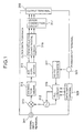
- Fig. 1 is a block diagram showing a card-type electronic tuner according to a third embodiment of the present invention.
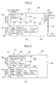
- Fig. 2 is a diagram showing a circuit layout according to the third embodiment.
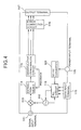
- Fig. 3 is a diagram showing another circuit layout according to the third embodiment.
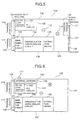
- Fig. 4 is a block diagram of a card-type electronic tuner according to a first embodiment of the invention.
- Fig. 5 is a diagram showing a circuit layout according to the first embodiment.
- Fig. 6 is a diagram showing another circuit layout according to the first embodiment.
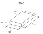
- Fig. 7 is a perspective view showing a profile of the first embodiment.
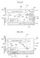
- Fig. 8 is a sectional view showing the same embodiment.
- Fig. 9 is an enlarged sectional view showing the essential parts of the first embodiment.
- Fig. 10 is another sectional view showing the first embodiment.
- Fig. 11A is a diagram for explaining single-axis extraction means.
- Fig. 11B is a diagram for explaining double-axis extraction means.
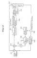
- Fig. 12 is a block diagram showing a card-type electronic tuner according to a second embodiment of the invention.
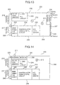
- Fig. 13 is a diagram showing a circuit layout according to the second embodiment.
- Fig. 14 is a diagram showing another circuit layout according to the second embodiment.
- Fig. 15 is a block diagram showing a card-type electronic tuner according to a fourth embodiment of the invention.
- Fig. 16 is a block diagram showing a card-type electronic tuner according to a fifth embodiment of the invention.
- Fig. 17 is a diagram showing a circuit layout according to the fifth embodiment.
- Fig. 18 is a diagram showing another circuit layout according to the fifth embodiment.
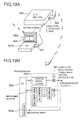
- Fig. 19A is a diagram for explaining a card-type electronic tuner as applied to the amusement sector according to the fifth embodiment, and Fig. 19B a block diagram thereof.
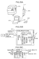
- Fig. 20A is a diagram for explaining a card-type electronic tuner as applied to the business sector, and Figs. 20B and 20C block diagrams thereof.
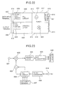
- Fig. 21A is a diagram for explaining a card-type electronic tuner as applied to factory production or the like, and Fig. 21B a block diagram thereof.
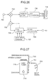
- Fig. 22 is a diagram showing a circuit layout for a card-type electronic tuner according to a sixth embodiment of the invention.
- Fig. 23 is a block diagram of a card-type electronic tuner according to the sixth embodiment.
- Fig. 24 is a diagram showing a circuit layout for a card-type electronic tuner according to a seventh embodiment.
- Fig. 25 is a diagram showing another circuit layout according to the seventh embodiment of the invention.
- Fig. 26 is a block diagram of the seventh embodiment.
- Fig. 27 is a sectional view showing the essential parts of the same embodiment.
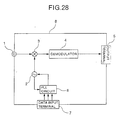
- Fig. 28 is a block diagram showing a conventional card-type electronic tuner.
- an electrical circuit of a card-type electronic tuner comprises a signal input terminal 111 supplied with a high-frequency signal, a mixer 113 having an input terminal supplied with a signal from the signal input terminal 111 and the other input terminal connected with the output of a local oscillator 112, digital signal extraction means 114 connected with the output of the mixer 113, a low-pass filter (not shown) connected with the output of the extraction means 114, a demodulator 115 using an analog circuit connected to the low-pass filter, an error correction circuit 116 connected with the output of the demodulator 115, an output terminal 117 connected with the output of the error correction circuit 116, a PLL circuit 118 having an input terminal connected with the output of the local oscillator 112 and a PLL signal output terminal connected to the input of the local oscillator 112, a data input terminal 119 for supplying a data signal to the PLL circuit 118, a power input terminal 120, and
- the high-frequency signal applied to the signal input terminal 111 provides an intermediate frequency signal after the tuning operation through the mixer 113 and the local oscillator 112.
- This intermediate frequency signal is demodulated into a digitally-processable signal form by the digital signal extraction means 114, the low-pass filter and the demodulator 115.
- the broadcast signal wave that has been digitally modulated is represented by a cosine wave, for example (the following explanation refers to the case using a cosine wave).
- the information "0" represents a phase difference
- the information "1" is delayed 180 degrees from the information "0".
- the delay of 180 degrees in phase is designated by attaching a minus sign to the cosine wave with phase difference of zero as shown in Equation 2.
- phase differences of 90 and 270 degrees may be assigned the phase differences of 90 and 270 degrees respectively.
- the phase differences of 0 and 180 degrees are assumed as an I signal, and the phase differences of 90 and 270 degrees as a Q signal.
- the coordinate axes of these signals are orthogonal to each other due to the phase differences thereof.
- the demodulating operation will be assumed to occur on the I axis in the following explanation.
- Equation 4 When a digitally-modulated signal is applied to a card-type electronic tuner, as shown in Equation 4, the input signal is multiplied by a cosine wave of the same frequency as the input signal at the extraction means 114, thereby producing a cosine wave having an absolute term and a frequency twice the original frequency.
- the absolute term is obtained by removing the two-fold frequency through a low-pass filter in the next stage. This absolute term finally provides a demodulation signal.
- ⁇ cos ⁇ t ⁇ cos ⁇ t ⁇ 1 2 (1+2 cos2 ⁇ t )
- the cosine wave thus supplied has some deviation in frequency and phase from the cosine wave generated in the extraction means 114.
- the demodulator 115 in the next stage extracts the fundamental frequency of the cosine wave by means of an analog resonator circuit. This signal is fed back to the extraction means 114 to correctly compensate for the cosine wave generated.
- a conventional analog circuit can be used as the demodulator 115 with a reduced cost.
- an analog local oscillator is used as the extraction means 114 and therefore a high intermediate frequency (band signal) can be input. Given a limited response rate of the feedback loop, however, the error rate increases for lack of synchronization in an area beyond the limit.
- the I and Q signals are separated and finally synthesized.
- the error rate unavoidably increases due to the deteriorated orthogonal accuracy between I and Q axes.
- Suitable applications therefore include those involving a comparatively small transmission amount (say, about 5 Kpbs) which is practicable even with a low transmission rate.
- Applicable products include digital portable telephones.
- the signal thus demodulated is 'applied to the error correction circuit 116 where an error thereof is corrected.
- An error-corrected signal is applied from the output terminal 117 to a personal computer, in which the signal is digitally processed.
- This case 122 has the same outer dimensions as the memory card inserted into the personal computer.
- the size is 85.6 mm (longitudinal dimension 123) by 54.0 mm (lateral dimension 124).
- the height 125 is 3.3 mm, 5.0 mm or 10.5 mm. With the height of 10.5 mm, the lateral size assumes 85.6 mm to a maximum of 135.6 mm.
- Outer dimensions other than described above may be defined.
- the outer surface of the case 122 is formed of an insulating synthetic resin, the interior of which is conductively plated with a metal. This metal plating is connected to the earth. A shield cover or a metal frame may be used instead of the metal plating.
- the card-type electronic tuner according to the invention has the same outer dimensions as a memory card, and therefore can be inserted without any hardware modification into the memory card slot of the personal computer. As a result, the digitally-modulated broadcast or the like can be received without changing the hardware of the personal computer.
- an output terminal 117, a data input terminal 119 and a power input terminal 120 are arranged on one lateral side 126 of a case 122. These terminals are fitted in a connector in the depth of the slot to exchange signals with the personal computer when the case 122 is inserted into the memory card slot. Also, a signal input terminal 111 is provided on the other lateral side 127 opposed to the lateral side 126. A rod antenna 128 is mounted on the signal input terminal 111. An external antenna may be connected to the signal input terminal 111 by cable in place of using the rod antenna.
- the signal input terminal 111 is mounted on the reverse side of the case 122 of the card-type electronic tuner, a high-frequency signal can be connected directly to the signal input terminal 111. It is therefore not necessary to take special measure to introduce a high-frequency signal into the personal computer. In other words, the personal computer can receive a digitally-modulated broadcasting without any hardware modification such as addition of an antenna to the personal computer.
- a printed board 129 is mounted in the case 122 and has the following circuits arranged thereon.
- An internal antenna 130 may be provided in the vicinity of the signal input terminal 111.
- a mixer 113 is arranged in the vicinity of the signal input terminal 111, and a local oscillator 112 is disposed in the vicinity of the mixer 113.
- a DC-DC converter 121 is packaged by being defined by a metal partitioning plate 131 (which may be made of other materials to the extent that such materials have a conductivity such as resin plating) in the vicinity of the power input terminal 120.
- a PLL circuit 118 is packaged in the vicinity of the data input terminal 119 by being defined by a metal partitioning plate 132.
- an error correction circuit 116 defined by a metal partitioning plate 133, a demodulator 115 defined by a metal partitioning plate 134 adjacently to the definition of the error correction circuit 116, and extraction means 114 defined by a metal partitioning plate 135 adjacently to the demodulator 115, are packaged in the vicinity of the output terminal 117.
- the PLL circuit 118 is located in the vicinity of a longitudinal side 136 of the case 122, while the digital signal processing means 137 including the extraction means 114, the demodulator 115 and the error correction circuit 116 is located in the vicinity of the other longitudinal side 138.
- the PLL circuit 118 and the digital signal processing means 137 thus are at some distance from each other.
- FIG. 6 Another circuit layout will be described with reference to Fig. 6.
- an output terminal 117, a data input terminal 119 and a power input terminal 120 are arranged on one lateral side 139 of a case 138 (which has the same outer dimensions as the case 122).
- the signal input terminal 111 is also arranged on the lateral side 139 (not shown). This signal input terminal 111 may alternatively be arranged on a longitudinal side 140 in the vicinity of the lateral side 139.
- This configuration corresponds to the case in which a high-frequency signal is already applied to the personal computer.
- a printed board 141 is mounted in the case 138.
- the printed board 141 has circuits arranged thereon in the manner mentioned below.
- An internal antenna 130 is arranged in the vicinity of the signal input terminal 111. This internal antenna 130 is not required in the case where a high-frequency signal is applied to the signal input terminal 111.
- a DC-DC converter 121 defined by a metal partitioning plate 142 is packaged in the vicinity of the power input terminal 120.
- a PLL circuit defined by a metal partitioning plate 143 is packaged in the vicinity of the data input terminal 119.
- an error correction circuit 116 defined by a metal partitioning plate 144, a demodulator 115 defined by a metal partitioning plate 145 adjacently to the error correction circuit 116, and extraction means 114 defined by a metal partitioning plate 146 adjacently to the demodulator 115, are packaged in the vicinity of the output terminal 117.
- the PLL circuit 118 is located in the vicinity of a longitudinal side 140 of the case 138, while digital signal processing means 137 including the extraction means 114, the demodulator 115 and the error correction circuit 116 is arranged in the vicinity of the other longitudinal side 147 of the case 138.
- the PLL circuit 118 and the digital signal processing means 137 are thus at some distance from each other. The reason is the same as that for the case shown in Fig. 5.
- the PLL circuit 118 and the digital signal processing means 137 are separated from each other by metal partitioning plates (132, 143; or 133, 134, 135 and 144, 145, 146).
- metal partitioning plates 132, 143; or 133, 134, 135 and 144, 145, 146.
- Fig. 8 shows a card-type electronic tuner comprising a case 148 (which has the same outer dimensions as the case 122), in which a multilayer printed board 149 is mounted with a PLL circuit 118 mounted on one side thereof and with the digital signal processing means 137 mounted on the other side thereof.
- Numeral 150 designates an aperture for adjusting the adjust parts such as a coil from outside.
- Fig. 9 is a sectional view showing the essential parts of the multlayer printed board 149.
- Numeral 151 designates an internal layer of the multilayer printed board 149. The earth is connected to the copper foill of the internal layer 151 for isolating the PLL circuit 118 and the digital signal processing means 137 from each other.
- a two-side printed board may be used in place of the multilayer printed board 149. In the case where parts are packaged on the two sides, the printed board is preferably mounted at the substantial center along the thickness of the case 148 to attain a high efficiency.
- Fig. 10 shows a card-type electronic tuner comprising a case 152 (which has the same outer dimensions as the case 122), in which two printed boards 153 and 154 are accommodated in two layers.
- the PLL circuit 118 is mounted on a printed board 153, while the digital signal processing means 137 is arranged on the other printed board 154.
- numeral 155 designates an aperture for adjusting the adjust parts such as a coil from outside.
- the two printed boards 153 and 154 are provided with the part-mounted sides thereof oriented outward to isolate the PLL circuit 118 and the digital signal processing means 137 from each other.
- this isolated structure into two sheets facilitates handling according to the capacity of the digital signal, handling by destination and addition of other optional functions simply by replacing the printed board 137 of the digital signal processing means. Insertion of a partitioning plate between the two printed boards can reduce interferences.
- Fig. 11 is a diagram for explaining the extraction means 114.
- Single-axis extraction means 114a is shown in Fig. 11A
- double-axis extraction means 114b for extracting orthogonal I and Q signals is illustrated in Fig. 11B.
- the former is used for FSK or BPSK, and the latter for QPSK, QPK or QAM.
- an electrical circuit of a card-type electronic tuner comprises a signal input terminal 211 supplied with a high-frequency signal, a mixer 213 having an input terminal supplied with the signal from the signal input terminal 211 and having the other input terminal thereof connected to the output of a local oscillator 212, an A/D converter 214 connected to the output of the mixer 213, a demodulator 215 including a digital circuit connected with the output of the A/D converter 214, an error correction circuit 216 connected to the output of the demodulator 215, an output terminal 217 connected to the output of the error correction circuit 216, a PLL circuit 218 having an input terminal thereof connected to the output of the local oscillator 212 and having a PLL signal output terminal connected to the input terminal of the local oscillator 212, a data input terminal 219 for supplying a data signal to the PLL circuit 218, a power input terminal 220 and a DC-DC converter 221 inserted between the
- the high-frequency signal applied to the signal input terminal 211 becomes an intermediate frequency through the tuning operation at the mixer 213 and the local oscillator 212.
- the information in this intermediate frequency signal is a digitally-modulated cosine wave, for example, and will hereinafter be referred to as the cosine wave.
- this cosine wave is split finely on time base directly, and converted into digital signals at the A/D converter 214.
- This digital information is directly applied to the demodulator 215, from which frequency and phase information are retrieved digitally.
- This information is fed back as clock data to the A/D converter 214 and synchronously detected.
- the phase can be synchronously detected in the demodulator 215, in which case the A/D converter 214 performs pseudo synchronous detection only for the frequency.
- the cosine wave information is directly processed in digital fashion, and therefore there occurs little phase deviation due to demodulation.
- the orthogonal accuracy of I and Q axes is high.
- the error rate is low.
- Use of the digital IC technique simplifies the circuit configuration suitably for size reduction.
- the high-speed A/D converter 214 and the demodulator 215 which handle the cosine wave information directly in digital fashion are expensive to use.
- a sufficiently high clock frequency is not yet available. Applications therefore are confined to a low-frequency narrow band signal.
- a case of narrow band is CATV of 6 MHz.
- the transmission rate of 30 Mbps is available using the QAM scheme.
- the demodulation signal thus produced is subsequently applied for error correction at the error correction circuit 216.
- An error-corrected signal is then applied toward the personal computer from the output terminal 217, and digitally processed in the personal computer.
- FIG. 13 An output terminal 217, a data input terminal 219 and a power input terminal 220 are provided on one lateral side 226 of a case 222 (which has the same outer dimensions as the case 122). These terminals, when the case 222 is inserted into a memory card insertion slot, are fitted into a connector in the depth of the slot to exchange signals with the personal computer.
- a signal input terminal 211 is provided on the other lateral side 227 in opposed relation to the lateral side 226. This signal input terminal 211 has a rod antenna 228 mounted thereon. An external antenna may be used in place of the rod antenna 228.
- the signal input terminal 211 is arranged on the reverse side of the case 222 of a card-type electronic tuner.
- a high-frequency signal can therefore be connected directly to the signal input terminal 211. It is not necessary to provide means for introducing a high-frequency signal into the personal computer. More specifically, digital broadcasting or the like can be received by the personal computer without modifying the hardware thereof.
- a printed board 229 is mounted in the case 222 and has the following circuits arranged thereon.
- An internal antenna 230 may be disposed in the vicinity of the signal input terminal 211.
- a mixer 213 is arranged in the vicinity of the signal input terminal 211, and a local oscillator 212 in the vicinity of the mixer 213.
- a DC-DC converter 221 defined by a metal partitioning plate 231 is packaged in the vicinity of the power input terminal 220.
- a PLL circuit 218 defined by a partitioning plate 232 is packaged in the vicinity of the data input terminal 219.
- an error correction circuit 216 defined by a metal partitioning plate 233, a demodulator 215 defined by a metal partitioning plate 234 adjacently to the error correction circuit 216, and an A/D converter 214 defined by a metal partitioning plate 235 adjacently to the demodulator 215, are packaged in the vicinity of the output terminal 217.
- the PLL circuit 218 is located in the vicinity of one longitudinal side 236 of the case 222, while the digital signal processing means 237 including the A/D converter 214, the demodulator 215 and the error correction circuit 216 is located in the vicinity of the other longitudinal side 238.
- the PLL circuit 218 and the digital signal processing means 237 are thus arranged at a distance from each other.
- FIG. 14 Another circuit layout will be explained with reference to Fig. 14.
- an output terminal 217, a data input terminal 219 and a power input terminal 220 are arranged on one lateral side 240 of a case 239 (which has the same outer dimensions as the case 122).
- a signal input terminal 211 is also arranged on the same lateral side 240 (not shown). This signal input terminal 211 may alternatively be arranged on the longitudinal side 241 in the vicinity of the lateral side 240.
- This case therefore corresponds to the case in which a high-frequency signal is already applied to the personal computer.
- the case 239 has a printed board 242 mounted therein.
- This printed board 242 has the following circuits arranged thereon.
- An internal antenna 230 is arranged in the vicinity of the signal input terminal 211.
- the internal antenna 230 is not required in the case where a high-frequency signal is applied to the signal input terminal 211.
- a DC-DC converter 221 is packaged by being defined by a metal partitioning plate in the vicinity of the power input terminal 220.
- a PLL circuit 218 is packaged by being defined by a metal partitioning plate 244 in the vicinity of the data input terminal 219.
- an error correction circuit 216 defined by a metal partitioning plate 245, a demodulator 215 defined by a metal partitioning plate 246 adjacently to the area of the error correction circuit 216, and an A/D converter 214 defined by a metal partitioning plate 247 adjacently to the demodulator 215, are packaged in the vicinity of the output terminal 217.
- the PLL circuit 218 is located in the vicinity of one longitudinal side 241 of the case 239, while the digital signal processing means 237 including the A/D converter 214, the demodulator 215 and the error correction circuit 216 is positioned in the vicinity of the other longitudinal side 248.
- the PLL circuit 218 and the digital signal processing means 237 thus are placed at a distance from each other. The reason for this is the same as that for the case shown in Fig. 13.
- the PLL circuit 218 and the digital signal processing means 237 are defined by metal partitioning plates (232, 244; or 233, 234, 235 and 245, 246, 247). In this way, the partitioning of the PLL circuit 218 and the digital signal processing means 237 from each other by a metal partitioning plate improves the isolation between the two circuits and prevents the PLL circuit 218 from having an effect on the digital signal processing means 237.
- Figs. 8, 9 and 10 the packaging method disclosed in Figs. 8, 9 and 10 is possible.
- parts may be concentrated on one side while patterns and printed resistors are formed on the other side, thereby further reducing the thickness.
- an electrical circuit of a card-type electronic tuner comprises a signal input terminal 311 supplied with a high-frequency signal, a mixer 313 having an input terminal supplied with a signal from the signal input terminal 311 and having the other input terminal connected to an output from a local oscillator 312, extraction means 314 connected with the output of the mixer 313, a low-pass filter (not shown) connected with the output of the extraction means 314, an A/D converter 315 connected with the output of the low-pass filter, a demodulator 316 using a digital circuit connected with the output of the A/D converter 315, an error correction circuit 317 connected to the output of the demodulator 316, an output terminal 318 connected to the output of the error correction circuit 317, a PLL circuit 319 having an input terminal connected to the output of the local oscillator 312 and having a PLL signal output terminal connected to the input terminal of the local oscillator 312, a data input terminal 320
- the high-frequency signal applied to the signal input terminal 311 makes up an intermediate frequency by being frequency-selected at the mixer 313 and the local oscillator 312.
- This intermediate frequency is applied to the extraction means 314, where the input digital modulated wave is multiplied by a cosine wave, for example, substantially equal to the modulated wave thereby to extract information as an absolute term.
- the double frequency which simultaneously appears in the process is removed by the low-pass filter inserted in the next stage.
- the modulated wave however, has some deviation from the cosine wave generated in the extraction means 314 in frequency and phase. Information attributable to this deviation is demodulated at the A/D converter 315 and the demodulator 316 using a digital circuit.
- the extraction means 314 thus has the feature that the use of an analog local oscillator as in the first embodiment makes it possible to apply a high intermediate frequency (i.e., broad-band signal).
- the local oscillator 312 may be fixed. If feedback is applied, on the other hand, the error rate is reduced. Also, all that is required of the A/D converter 315 or the demodulator 316 using a digital circuit is to complement the demodulation due to the small frequency or phase deviation caused in the extraction means 314. Therefore, the processing speed of the A/D converter 315 or the demodulator 316 need not be high, thus realizing a low-cost demodulator.
- the demodulation signal thus obtained is applied to the error correction circuit 317 where the error contained in the signal is corrected.
- the resulting error-corrected signal is output from the output terminal 318 toward the personal computer and digitally processed in the latter.
- the highest frequency i.e., broad-band of, say, 20 MHz in the satellite broadcasting
- a transmission rate as large as 40 Mbps for QPSK in the state of art.
- an output terminal 318, a data input terminal 320 and a power input terminal 321 are arranged on one lateral side 326 of a case 323 (which has the same outer dimensions as the case 122). These terminals, when the case 323 is inserted into a memory card insertion slot, are fitted into a connector in the depth of the slot to exchange signals with the personal computer.
- a signal input terminal 311 is disposed on the other lateral side 327 in opposed relation to the lateral side 326. This signal input terminal 311 has a rod antenna 328 mounted thereon. The signal input terminal 311 may alternatively be connected with an external antenna by cable.
- the signal input terminal 311 is placed on the reverse side of the case 323 of the card-type electronic tuner, and therefore a high-frequency signal can be directly connected to the signal input terminal 311.
- a high-frequency signal need not be introduced into the personal computer.
- the digital broadcasting or the like can be received by the personal computer without modifying the hardware thereof.
- a printed board 329 mounted in the case 323 has the following circuits arranged thereon.
- An internal antenna 330 may be arranged in the vicinity of the signal input terminal 311.
- a mixer 313 is arranged in the vicinity of the signal input terminal 311, and a local oscillator 312 is placed in the vicinity of the mixer 313.
- a DC-DC converter 322 is packaged by being defined by a metal partitioning plate 331 in the vicinity of the power input terminal 321.
- a PLL circuit 319 is packaged by being defined by a metal partitioning plate 332 in the vicinity of the data input terminal 320.
- an error correction circuit 317 defined by a metal partitioning plate 333
- a demodulator 316 defined by a metal partitioning plate 334 adjacently to the definition of the error correction circuit 317
- an A/D converter 315 defined by a metal partitioning plate 335 adjacently to the demodulator 316
- extraction means 314 defined by a metal partitioning plate 336 adjacently to the A/D converter 316
- the PLL circuit 319 is located in the vicinity of one longitudinal side 337 of the case 323, while digital signal processing means 338 including the extraction means 314, the A/D converter 315, the demodulator 316 and the error correction circuit 317 is arranged in the vicinity of the other longitudinal side 339 of the case 323, so that the PLL circuit 319 and the digital signal processing means 338 are at some distance from each other.
- FIG. 3 Another circuit layout will be explained with reference to Fig. 3.
- an output terminal 318, a data input terminal 320 and a power input terminal 321 are arranged on one lateral side 341 of a case 340 (which has the same outer dimensions as the case 122).
- a signal input terminal 311 is also arranged on the same lateral side 341 (not shown). This signal input terminal 311 may alternatively be provided on one longitudinal side 342 in the vicinity of the lateral side 341.
- This case therefore corresponds to the case in which a high-frequency signal is already applied to the personal computer.
- a printed board 343 is mounted in the case 340, and has the following circuits arranged thereon.
- An internal antenna 330 is arranged in the vicinity of the signal input terminal 311. This internal antenna 330 is not required in the case where a high-frequency signal is applied to the signal input terminal 311.
- a DC-DC converter 322 is packaged by being defined by a metal partitioning plate 344 in the vicinity of the power input terminal 321.
- a PLL circuit 319 is arranged by being defined by a metal partitioning plate 345 in the vicinity of the data input terminal 320.
- an error correction circuit 317 defined by a metal partitioning plate 346, a demodulator 316 defined by a metal partitioning plate 347 adjacently to the definition of the error correction circuit 317, an A/D converter 315 defined by a metal partitioning plate 348 adjacently to the demodulator 316 and extraction means 314 defined by a metal partitioning plate 349 adjacently to the A/D converter 315, are packaged in the vicinity of the output terminal 318.
- the PLL circuit 319 is located in the vicinity of one longitudinal side 350 of the case 340, while the digital signal processing means 338 including the extraction means 314, the A/D converter 315, the demodulator 316 and the error correction circuit 317 is located in the vicinity of the other longitudinal side 351, so that the PLL circuit 319 and the digital signal processing means 338 are at some distance from each other.
- the reason is the same as that for the case shown in Fig. 2.
- the PLL circuit 319 and the digital signal processing means 338 are separated from each other by metal partitioning plates (332, 345; or 333, 334, 335, 336 and 346, 347, 348, 349).
- metal partitioning plates 332, 345; or 333, 334, 335, 336 and 346, 347, 348, 349.
- separation of the PLL circuit 319 from the digital signal processing means 338 by a metal partitioning plate improves the isolation between the two circuits and prevents the PLL circuit 319 from having an effect on the digital signal processing means 338.
- the packaging disclosed in Figs. 8, 9 and 10 may alternatively be implemented.
- the thickness can be further reduced by concentrating the parts on one side with patterns and printed resistors formed on the other side.
- Fig. 15 shows a fourth embodiment of the invention.
- an electrical circuit of a card-type electronic tuner according to the invention comprises a signal input terminal 411 supplied with a high-frequency signal, a first mixer 413 having an input terminal supplied with the signal from the signal input terminal 411 and the other input terminal connected with the output of a first local oscillator 412, an intermediate frequency amplifier 414 connected with the output of the first mixer 413, a second mixer 416 having an input terminal thereof connected to the output of the intermediate frequency amplifier 414 and the other input terminal connected with the output of the second local oscillator 415, extraction means 417 connected to the output terminal of the second mixer 416, a low-pass filter (not shown) connected with the output of the extraction means 417, an A/D converter 418 connected with the output of the low-pass filter, a demodulator 419 using a digital signal connected with the output of the A/D converter 418, an error correction circuit 420 connected with the output terminal of the demodulator 419, an output terminal 421 connected
- circuits are accommodated in the case identical to the case 122 as in the aforementioned embodiment. Also, with regard to arrangement of parts, it is important to insert a metal partitioning plate between the first mixer 413 and the first local oscillator 412 and between the second mixer 416 and the second local oscillator 415 thereby to improve isolation and thus prevent each part from interfering with another.
- a high-frequency signal of, say, 300 MHz input to the signal input terminal 411 makes up a first intermediate frequency of about 27 MHz by being tuned by the first mixer 413 and the first local oscillator 412.
- This intermediate frequency is reconverted in frequency by the second mixer 416 and the second oscillator 415 into a second intermediate frequency of, say, about 450 kHz.
- the digital modulation wave derived from the extraction means 417 is multiplied by a cosine wave substantially equal to the modulation wave, so that information is extracted as an absolute term.
- the double frequency appearing in this process is removed by a low-pass filter inserted in the next stage.
- the modulation wave however, has some deviation from the cosine wave generated in the extraction means 417 in frequency and phase. Information attributable to this deviation is demodulated at the A/D converter 418 and the demodulator 419 using a digital circuit in the next stage. An error is then corrected at the error correction circuit 420. This error-corrected signal is applied to the personal computer from the output terminal 421 and digitally processed in the personal computer.
- two mixers are employed to reduce image interferences. Consequently, a high-density communication with small frequency intervals is made possible.
- Figs.5, 6, 8, 9 and 10 may alternatively be used in the embodiment under consideration.
- an electrical circuit of a card-type electronic tuner comprises a signal input/output terminal 511 for producing and receiving a high-frequency signal, a duplexer 512 connected with the signal from the signal input/output terminal 511, a first mixer 514 having an input terminal supplied with the output of the duplexer 512 and the other input terminal connected with the output terminal of a first local oscillator 513, extraction means 515 connected with the output signal of the first mixer 514, a low-pass filter (not shown) connected with the output of the extraction means 515, an A/D converter 516 connected with the output of the low-pass filter, a demodulator 517 using a digital circuit connected with the output of the A/D converter 516, an error correction circuit 518 connected with the output of the demodulator 517, an output terminal 519 connected with the output terminal of the error correction circuit 518, a first PLL circuit 520 having an input terminal connected with the output of the first
- the card-type electronic tuner according to the invention can be inserted directly into a memory card slot without modifying the hardware of the personal computer.
- a high-frequency signal applied to the signal input/output terminal 511 is applied through a duplexer 512 and, by way of the tuning operation by the mixer 514 and the local oscillator 513, makes up an intermediate frequency.
- This intermediate frequency is digitally demodulated by the extraction means 515, the A/D converter 516 and the demodulator 517 using a digital circuit.
- This demodulation signal is corrected in error by the error correction circuit 518.
- the error-corrected signal is output toward the personal computer from the output terminal 519 and is digitally processed in the personal computer.
- the signal applied to the transmission signal input terminal 524 is digitally modulated at the digital modulation processing means 525 according to, say, Equation 3. ⁇ cos ⁇ t
- the digitally-modulated signal is carried on a carrier wave of, say, about 300 MHz through the second mixer 527 and the second local oscillator 526 in the next stage and is power amplified at the high-frequency amplifier 528.
- the output of the high-frequency amplifier 528 is applied through the duplexer 512 to the signal input/output terminal 511.
- the duplexer 512 is inserted for the purpose of preventing the signal of the transmission system from circumventing into the receiving system.
- a card-type electronic tuner comprises a transmission system in addition to a receiving system and therefore is capable of bidirectional digital transmission.
- a circuit layout will be described in detail with reference to Fig. 17.
- a case 531 (which has the same outer dimensions as the case 122) is split into two parts for packaging the transmission system and the receiving system. Only the transmission system will be described since the same consideration as in the third embodiment applies to the receiving system.
- a transmission signal input terminal 524 and a second data input terminal 530 are provided on a lateral side 532 of the case 531. These terminals, when the case 531 is inserted into the memory card slot, are fitted in the connector provided in the depth of the slot thereby causing signals to be exchanged with the personal computer.
- a signal input/output terminal 511 is provided on the other lateral side 533 in opposed relation to the lateral side 532. This signal input/output terminal 511 has a rod antenna 534 mounted thereon. This signal input/output terminal 511 may alternatively be connected to an external antenna by means of cable.
- the signal input/output terminal 511 is located on the reverse side of the case 531 of the card-type electronic tuner, a high-frequency digital signal can be directly connected to the signal input/output terminal 511. As a result, it is not necessary to introduce a high-frequency signal into the personal computer. More specifically, digital broadcasting or the like can be transmitted to or received by the personal computer without changing the hardware of the personal computer. Also, a printed board 535 is mounted in the case 531 and has the following circuits arranged thereon. An internal antenna 536 may be provided in the vicinity of the signal input/output terminal 511.
- duplexer 512 the second mixer 527 and the second local oscillator 526 are arranged in that order toward the lateral side 532 in the vicinity of the signal input/output terminal 511.
- the output of the duplexer 512 is wired to the definition chamber 537 of the receiving system.
- the digital modulation processing means 525 is provided on one longitudinal side 540 by being surrounded by a metal partitioning plate 539 adjacently to a transmission signal input terminal 524 provided on the lateral side 532.
- the transmission system and the receiving system are isolated from each other by a metal partitioning plate 541
- the second PLL circuit 529 is disposed adjacently to the second data input terminal 530 on the lateral side 532 separated by a metal partitioning plate 542.
- the digital modulation processing means 525 is packaged at a point distant from the second PLL circuit 529 and is isolated therefrom in terms of high frequency by means of partitioning plates 539 and 542. Also, the second local oscillator 526 and the first local oscillator 513 packaged in the receiving system are separated with some spatial distance from each other and isolated in terms of high frequency by the partitioning plate 541.
- FIG. 18 Another circuit layout will be described with reference to Fig. 18.
- a case 545 (which has the same outer dimensions as the case 122) is isolated into two portions by a metal partitioning plate 546.
- a transmission system is packaged on one longitudinal side 547 thereof, and a receiving system on the other longitudinal side 548. Since the receiving system is based on the same concept as the third embodiment, description will be made only about the transmission system.
- a transmission signal input terminal 524 and a second data input terminal 530 are provided on a lateral side 549 of the case 545. These terminals, when the case 545 is inserted into a memory card insertion slot,are fitted into a connector in the depth of this slot to exchange signals with the personal computer. Also, a signal input/output terminal 511 is provided on a lateral side 549 or on a longitudinal side 548 in the vicinity of the lateral side 549. The signal input/output terminal 511 may alternatively be provided on the lateral side 549.
- a printed board 550 is mounted in the case 545 and has the following circuits arranged thereon.
- a duplexer 512 is provided in the vicinity of the signal input/output terminal 511.
- Numeral 513 designates a first local oscillator provided in the receiving system.
- Numeral 527 designates a second mixer arranged in the vicinity of the other lateral side 551 in the transmission system.
- the second local oscillator 526 is arranged on one longitudinal side 547.
- the digital modulation processing means 525 is arranged on the longitudinal side 547 surrounded by a metal partitioning plate 552 adjacently to the transmission signal input terminal 524 on the lateral side 549.
- the second PLL circuit 529 which is separated by a metal partitioning plate 553, is arranged on the other longitudinal side 548 adjacently to the second data input terminal 530 on the lateral side 549.
- the digital signal processing means 525 is packaged at some distance from the second PLL circuit 529 on the one hand and is insulated in terms of high frequency by means of partitioning plates 552 and 553 therebetween. Also, the second local oscillator 526 and the first local oscillator 513 packaged in the receiving system are isolated from each other with some spatial distance therebetween and are insulated in terms of high frequency from each other by means of a partitioning plate 546.
- Fig. 19A shows an example of application as an amusement machine
- Fig. 19B a block diagram thereof.
- numeral 560 designates a personal computer
- numeral 561 a bidirectional card-type electronic tuner inserted in the memory card insertion slot of the personal computer 560.
- the digital broadcasting wave from an external source is received by an antenna 560a provided in the personal computer 560.
- This information is processed by screen splitting or textual insertion using a keyboard 560b or a display 560c of the personal computer 560.
- the information thus processed is recorded by being received through the card-type electronic tuner 563 inserted in the memory slot of the VTR 562 (which may be replaced by a mini disk (MD), a digital video disk (DVD) or the like) by cable or radio from the signal input/output terminal 511 of the card-type electronic tuner.
- the signal output from the card-type electronic tuner 561 may be printed in hard copy by means of printer or monitored by being transmitted to another personal computer or TV.
- the signal may alternatively be transmitted from the antenna 560a in the personal computer 560 with the transmission output on the slot side.
- Fig. 20A shows an example of application to business
- Figs. 20B and 20C block diagrams thereof.
- numeral 570 designates a personal computer.
- a public telephone 572 or a portable telephone 573 is connected to a host computer in the head office using a bidirectional card-type electronic tuner 571 inserted in the personal computer 570 for processing business information generated by the user while on tour.
- data resident in the host computer is read and an estimate is submitted on the spot. If the negotiation is successful, a production order is issued directly to the host computer according to the received order.
- a digital portable telephone in view of the fact that a mixer and a local oscillator are already included in the card-type tuner, a digital portable telephone, if one is used, can be connected to the output of a duplexer as shown in the block diagram of Fig. 20B.
- the mixer and the local oscillator for the card-type tuner shown in Fig. 20C are not required since transmission may be by baseband.
- a change-over switch is provided in the card-type tuner for bypassing the mixer and the local oscillator as required, thereby making possible adaptation to both the digital portable telephone and the digital public telephone.
- the digital processing means of the receiving system in the card-type tuner may include either extraction means or an A/D converter but not both of them according to the frequency and transmission rate.
- the mixer or the local oscillator in stages subsequent to the digital modulation processing means of the card-type tuner are not built in the transmission system.
- the output of the digital modulation processing means of the card-type tuner is supplied to the input of the mixer in the transmission system of the digital portable telephone through a connection terminal.
- the output from the digital modulation processing means of the card-type tuner is supplied directly.
- a configuration having a protrusion as designated by numeral 574 may be provided to meet the increased circuit requirements of the transmission system.
- Fig. 21A shows an example used for factory production or the like, and Fig. 21B a block diagram thereof.
- numeral 580 designates a personal computer.
- This personal computer 580 is used for controlling a machine tool 582 or a measuring instrument 583 located at a distance by means of a bidirectional card-type tuner 581.
- the information (yield, etc., for example) from the machine tool 582 or the measuring instrument 583 can be obtained from the bidirectional card-type tuner 584 inserted in the particular machine tool or the measuring instrument, as the case may be.
- both the transmission and receiving systems have a mixer and a local oscillator.
- Fig. 22 is plan view showing a card-type tuner according to a sixth embodiment of the invention, and Fig. 23 is a block diagram thereof.
- an electronic tuner comprises a signal input terminal 601, a mixer 603 having an input thereof supplied with the signal from the signal input terminal 601 and the other input terminal thereof supplied with the output of a local oscillator 602, a demodulator 604 supplied with the output 'of the mixer 603, an A/D converter 608 supplied with the output of the demodulator 604, an output terminal 605 supplied with the output of the A/D converter 608, and a PLL circuit 606 connected to a data input terminal 607 for controlling the oscillation frequency of the local oscillator 602, all of which are accommodated in a card-type case 613 shown in the drawing.
- the output terminal 605, the data input terminal 607 and the power input terminal 614 are arranged on one lateral side 615 of the case 613, while the signal input terminal 601 is disposed on the other lateral side 616 of the case 613.
- the other lateral side 616 can be exposed out of the apparatus.
- the provision of the signal input terminal 601 at the exposed part makes it possible to introduce a high-frequency signal to the signal input terminal 601 without the need of reconstruction of the apparatus.
- the longitudinal side 617 or 618 in the vicinity of the other lateral side 616 of the case 613 may be exposed from the apparatus to allow the signal input terminal 601 to be arranged on the exposed longitudinal side 617 or 618.
- a defined section for accommodating a tuner 612 including the mixer 603 and the local oscillator 602 is arranged in the vicinity of the input terminal 601.
- a defined section for the PLL circuit 606 is provided between the tuner 612, the data input terminal 609 on the lateral side 615 and the longitudinal side 617.
- a DC-DC converter 609 is packaged in the vicinity of the power input terminal 614. In this way, provision is made to isolate the digital signal system and the high-frequency signal system from each other as far as possible.
- a section for the demodulator 604 is defined between the tuner 612, the output terminal 605 on the lateral side 615 and the longitudinal side 618.
- An A/D converter 608 is arranged in proximity to the output terminal 605.
- An audio multiplexing circuit is inserted between the demodulator 604 and the output terminal 605, and is arranged in the vicinity of the output terminal 605. This is in order to enjoy stereo broadcasting.
- An antenna system is arranged in the vicinity of the signal input terminal 601 and the other lateral side 616.
- an internal antenna 610 is mounted within the case 613, and is connected to the signal input terminal 601.
- the antenna 610 is arranged in the vicinity of the signal input terminal 601.
- the tuner 612 configured of the mixer 603 and the local oscillator 602 is arranged in the vicinity of the signal input terminal 601.
- the PLL circuit 606 and the demodulator 604 are separated by a metal partitioning plate.
- the PLL circuit 606 is arranged adjacently to the data input terminal 607 thereby to prevent the digital signal such as a clock from having an effect on the tuner 612.
- the demodulator 604 is arranged in the vicinity of the output terminal 605, and the A/D converter 608 is connected between the demodulator 604 and the output terminal 605. This A/D converter 608 is inserted between the demodulator 604 and the output terminal 605.
- the power supply uses the DC-DC converter 609 in order to secure a single power supply.
- This DC-DC converter 609 is connected to the power input terminal 614.
- the output of the DC-DC converter 609 is connected to a tuning voltage generator circuit of the PLL circuit 600 thereby to produce a tuning voltage to be supplied to the local oscillator 602.
- power is converted into the required voltage from the power input terminal 614 and supplied to the mixer 603, the local oscillator 602, the demodulator 604, the A/D converter 608, etc.
- a bar antenna is used and arranged substantially in parallel to the lateral sides of the card.
- a rod antenna may be used on the outside of the card 613 on the lateral side 616.
- a tabular antenna 611 may be used with the shorter side thereof having a crescent section. This is what is called in the shape of the measuring scale.
- the television video and audio signals supplied by way of the signal input terminal 601 through the antenna 610 or 611 are applied to the tuner 612 including the mixer 603 and the local oscillator 602 for selecting the desired channel.
- the video signal demodulated by the demodulator 604 is applied to the A/D converter 608 for Y-C separation, with the resulting RGB output being applied directly on the screen of the apparatus.
- the audio signal can be directly output from the speaker of the apparatus.
- a card-type electronic tuner of the invention is inserted into the apparatus such as the personal computer or the video movie, so that the television picture and sound can be received without connecting any special terminal as a signal input terminal in the apparatus.
- a card-type electronic tuner comprises the output terminal 605 and the data input terminal 607 arranged on one lateral side 615, while the signal input terminal 601 is arranged on the other lateral side 616 or on the longitudinal side 617 in the vicinity of the lateral side 616 of the case 613.
- the television signal can be directly connected to the signal input terminal 601 without the need of providing a signal input terminal in the apparatus.
- the antenna 610 is connected to the signal input terminal 601 and is accommodated in the case 613 provided in the vicinity of the signal input terminal 601. As a result, in a region with a strong electric field, the television picture and sound and the AM radio broadcasting can be received without the trouble of using an external antenna. Since the antenna 610 is accommodated in the case 613, the antenna is readily protected while not in use.
- the tuner 612 is arranged in the vicinity of the signal input terminal 601, the television signal supplied by way of the signal input terminal 601 can be minimized in input level attenuation. Further, the signals other than for the desired channel can be prevented from interfering with other circuits such as the demodulator 604 at the time of receiving.
- the AM radio broadcasting can be received without using an external antenna with a highly-sensitive signal being supplied to the mixer 603.
- the TV picture and sound can be received with a highly-sensitive television signal being supplied to the mixer 603.
- the antenna 611 is shaped in tabular form with the shorter side thereof having a crescent section in what may be called the measuring scale style, the antenna 611 is improved in accommodability and can be readily protected when not in use. This permits the receiving of the television video and audio signals of a quality equivalent to that with the rod antenna, with the result that a highly-sensitive signal can be supplied to the mixer 603.
- the PLL circuit 606 is provided adjacently to the data input terminal 607, radiation of control signals including the clock signal, data signal and the enable signal from the data input terminal 607 is minimized. Also, the interference from other oscillation circuits with the control signal line can be prevented.
- the provision of the A/D converter 608 between the demodulator 604 and the output terminal 605 within the case 613 makes it possible to output the television picture directly on the display of the apparatus without arranging any A/D converter 608 on the apparatus side.
- the load on the apparatus can be reduced without the need of providing the A/D converter 608 on the apparatus.
- the interference of high harmonics or the like with the video signal after demodulation can be minimized since the circuits involved are some distance away from the oscillation circuit 602.
- the adjacency between the A/D converter 608 and the output terminal 605 reduces to a minimum the interference of high harmonics from other circuits such as the oscillation circuit 602 with the A/D-converted signal.
- the DC-DC converter 609 is connected to the power input terminal 614 while the output of the DC-DC converter 609 is connected to the PLL circuit 606, the DC power (30 volts) generated by the DC-DC converter 609 is immune to noises from other circuits, thereby providing a stable power supply. Also, since the DC-DC converter 609 is built in the apparatus, there is no need of providing the DC-DC converter 609 in the apparatus. The load on the apparatus thus can be reduced.
- Figs. 24 and 25 show a circuit layout of a card-type electronic tuner according to a seventh embodiment of the invention
- Fig. 26 is a block diagram of the same embodiment.
- an electronic tuner comprises a signal input terminal 701, a mixer 703 having an input supplied with the signal from the signal input terminal 701 and the other input terminal supplied with the output from a local oscillator 702, a demodulator 704 supplied with the output from the mixer 703, an A/D converter 708 supplied with the output from the demodulator 704, an output terminal 705 supplied with the output from the A/D converter 708, a PLL circuit 706 connected to the data input terminal 707 for controlling the oscillation frequency of the local oscillator 702, and a DC-DC converter 709 connected to the power input terminal 714 for supplying a tuning voltage to the PLL circuit 706.
- the output terminal 705, the data input terminal 707 and the power input terminal 714 are arranged on one lateral side 715 of the case 713, while the signal input terminal 701 is disposed on the lateral side 715 of the case 713 or on the longitudinal side 716 in the vicinity of the lateral side 715 thereof.
- a high-frequency signal can be introduced directly into the signal input terminal 701 from a dedicated connector provided for the card-type electronic tuner such as in a TV camera.
- the apparatus proper 720 need not be reconstructed with respect to the general-purpose connector for the personal computer, and as shown in Fig. 27, a high-frequency signal can be introduced into the signal input terminal 701 from the side of the apparatus 720.
- Sections defined for the internal antenna 710 and the tuner 712 including the mixer 703 and the local oscillator 702 in that order are arranged from the longitudinal side 716.
- a section is defined for the PLL circuit 706 adjacently to the tuner 712 between the lateral side 715 and the data input terminal 707.
- the DC-DC converter 709 is packaged in the vicinity of the power input terminal 714.
- a section for the demodulator 704 is defined between the tuner 712, the output terminal 705 of the lateral side 715 and the other longitudinal side 717.
- the A/D converter 708 is arranged in the vicinity of the output terminal 705.
- An audio multiplexing circuit may be inserted between the demodulator 704 and the output terminal 705 and may be arranged in the vicinity of the output terminal 705. This is for the purpose of enjoying the stereo broadcasting.
- a signal input terminal 701 is provided as an antenna input on the lateral side 715 or on the longitudinal side 716 in the vicinity of the lateral side 715.
- An internal antenna 710 is mounted in the case 713 and connected to the signal input terminal 701. Also, an antenna 710 is arranged in the vicinity of the signal input terminal 701. In the case where the antenna 710 is accommodated in the case 713 in this fashion, the receiving operation is possible without an external antenna.
- the tuner 712 is separated from the PLL circuit 706 and the demodulator 704 by a metal partitioning plate.
- the PLL circuit 706 is provided adjacently to the data input terminal 707 in order to prevent the digital signal such as a clock from affecting the tuner 712.
- the demodulator 704 is arranged in the vicinity of the output terminal 705, and the A/D converter 708 is interposed between the demodulator 704 and the output terminal 705.
- the A/D converter 708 in turn is arranged between the demodulator 704 and the output terminal 705.
- the power supply uses the DC-DC converter 709 to provide a single power supply.
- the DC-DC converter 709 is connected to the power input terminal 714.
- the output of this DC-DC converter 709 is connected to the tuning voltage generator circuit of the PLL circuit 706 to produce a tuning voltage to be supplied to the local oscillator 702.
- the power supplied from the power input terminal 714 is converted into the required voltage, and is supplied to the mixer 703, the local oscillator 702, the demodulator 704, the A/D converter 708, etc.
- a bar antenna may be used and arranged substantially in parallel to the longitudinal side 716 of the case 713.
- a rod antenna 711 may be used and mounted on a signal input terminal external to the case 713 on the longitudinal side 710.
- An antenna cable 721 may of course be inserted in place of the rod antenna 711.
- a plan view of the essential parts representing this usage is shown in the drawing.
- the television video and audio signals supplied from the signal input terminal 701 through the internal antenna 710 or the external rod antenna 711 are applied to the tuner 712 including the mixer 703 and the local oscillator 702 thereby to select the desired channel.
- the video signal is demodulated by the demodulator 704, and the resulting demodulated video signal is subjected to YC separation at the A/D converter 708 followed by being applied directly to the screen of the apparatus as an RGB output.
- the audio signal may be produced directly from the speaker of the apparatus.
- a card-type electronic tuner according to the invention is inserted into the apparatus proper such as a personal computer or a video camera to receive the TV picture and sound. Also, according to the embodiment shown in Fig. 25, the receiving operation is possible without providing the signal input terminal 1 as a special terminal on the apparatus side.
- the antenna 710 is connected to the signal input terminal 701, arranged in the vicinity of the signal input terminal 701 and accommodated in the case 713.
- the television video and audio signals and the AM radio broadcasting can be received without taking trouble of using a separate external antenna in a region with strong electric field.
- the antenna 710 is accommodated in the case 713, the antenna can be readily protected while not in use.
- the tuner 712 arranged in the vicinity of the signal input terminal 701 the attenuation of the input level of the television signal supplied through the signal input terminal 701 can be minimized. Further, signals other than for the desired channel are prevented from interfering with other circuits such as the demodulator 704 at the time of receiving.
- the antenna 710 is configured of a bar antenna integrated substantially in parallel to the longitudinal side 716 of the case 713, the AM radio broadcasting can be received without using an external antenna. A highly sensitive signal can thus be supplied to the mixer 703.
- an external rod antenna 711 external to the case 713 permits the television picture and sound to be received, and thus a highly-sensitive television signal can be supplied to the mixer 703.
- the rod antenna 711 is of replaceable type, an antenna not in use is easy to protect.
- control signals including the clock signal, data signal and the enable signal from the data input terminal 707 can be minimized. Further, interferences of other oscillation circuits with the control signals can be prevented.
- the demodulator 704 is arranged in the vicinity of the output terminal 705, and therefore the interference of harmonics from other circuits including the local oscillation circuit 702 with the video and audio signals after demodulation is minimized.
- the A/D converter 708 Since the A/D converter 708 is inserted between the output terminal 705 and the demodulator 704 in the case 713, the television picture can be output directly to the display unit of the apparatus without arranging the A/D converter 708 on the apparatus. As a result, it is not necessary to provide the A/D converter 708 in the apparatus thereby reducing the load imposed on the apparatus. Further, since the video signal after demodulation is distant from the local oscillation circuit 702, the interference from harmonics or the like can be minimized. Furthermore, the A/D converter 708 and the output terminal 705 being located adjacently to each other reduces the interference of harmonics or the like with the signal after A/D conversion from other circuits including the local oscillation circuit 702.
- a card-type electronic tuner comprising a signal input terminal supplied with a high-frequency signal, a mixer having an input terminal supplied with the signal from the signal input terminal and the other input terminal supplied with the output from a local oscillator, an output terminal supplied with the output signal from the mixer, a PLL circuit having an input terminal connected to the output of the local oscillator and a PLL signal output terminal connected to the input terminal of the local oscillator, and a data input terminal for supplying a data signal to the PLL circuit, all of which are accommodated in a card-type case.
- the output terminal and the data input terminal are arranged on one lateral side of the case, while digital signal processing means including extraction means and/or an A/D converter is inserted between the mixer and the output terminal.
- digital signal processing means including extraction means and/or an A/D converter is inserted between the mixer and the output terminal.
- the digital broadcasting therefore can be received directly and the data thereof can be introduced into the personal computer or the like.
- the expansion slot for the memory card can be used as it is without any modification or reconstruction of the hardware of the personal computer.
Landscapes
- Engineering & Computer Science (AREA)
- Computer Hardware Design (AREA)
- Microelectronics & Electronic Packaging (AREA)
- Structure Of Receivers (AREA)
- Superheterodyne Receivers (AREA)
Claims (31)
- Elektronischer Tuner, welcher ein digital moduliertes Signal in ein Basisbandsignal umwandelt, aufweisend:dadurch gekennzeichnet, dass alle Bestandteile des elektronischen Tuners in einem Gehäuse vom Kartentyp untergebracht sind, der Ausgangsanschluss (318) und der Daten-Eingangsanschluss (320) an einer Querseite des Gehäuses angeordnet sind, und die PLL-Schaltung (319) von der Digitalsignal-Verarbeitungseinrichtung im Wesentlichen isoliert angeordnet ist, so dass ein Taktimpuls von der PLL-Schaltung (319) keinen wesentlichen Effekt auf die Digitalsignal-Verarbeitungseinrichtung hat.einen Signal-Eingangsanschluss (311), dem ein Hochfrequenzsignal zugeführt wird;einen Mischer (313), dessen Eingangsanschluss ein Signal vom Signal-Eingangsanschluss (311) zugeführt wird und dessen anderem Eingangsanschluss eine Ausgangsgrösse eines lokalen Oszillators (312) zugeführt wird;einen Ausgangsanschluss (318), dem ein Ausgangssignal des Mischers (313) zugeführt wird;eine PLL-Schaltung (319), deren Eingangsanschluss mit dem Ausgangsanschluss des lokalen Oszillators (312) und deren PLL-Signal-Ausgangsanschluss mit einem Eingangsanschluss des lokalen Oszillators (312) verbunden ist;einen Daten-Eingangsanschluss (329), welchem ein Datensignal der PLL-Schaltung (319) zugeführt wird; undeine Digitalsignal-Verarbeitungseinrichtung, die beinhaltet: mindestens eine gewählte Extraktionseinrichtung (314), welche eine Frequenzumsetzung durchführt, um aus einer Trägerwelle in einem digital modulierten Ausgangssignal des Mischers (313) ein digitales Signal zu extrahieren, und welche bei einer digitalen Signalverarbeitung des extrahierten Signals verwendet wird, und einen A/D-Wandler (315), der sich zwischen Mischer (315) und Ausgangsanschluss (318) befindet;
- Elektronischer Tuner nach Anspruch 1, dadurch gekennzeichnet, dass der Signal-Eingangsanschluss, dem ein Hochfrequenzsignal zugeführt wird, auf einer ausgewählten Querseite des Gehäuses angeordnet ist, an welcher der Daten-Eingangsanschluss angebracht ist, wobei sich eine Längsseite des Gehäuses in der Nähe der Querseite befindet und die PLL-Schaltung in der Nähe des Daten-Eingangsanschlusses angeordnet ist.
- Elektronischer Tuner nach Anspruch 1, dadurch gekennzeichnet, dass der Signal-Eingangsanschluss, dem ein Hochfrequenzsignal zugeführt wird, auf der anderen gewählten Querseite gegenüberliegend der Querseite angebracht ist, an welcher der Daten-Eingangsanschluss befestigt ist, wobei sich eine Längsseite in der Nähe der anderen Querseite befindet.
- Elektronischer Tuner nach Anspruch 1, dadurch gekennzeichnet, dass die PLL-Schaltung in der Nähe einer Seite einer in das Gehäuse eingebauten Platine angeordnet ist, und eine digitale Verarbeitungseinrichtung in der Nähe der anderen Seite der Platine angeordnet ist.
- Elektronischer Tuner nach Anspruch 1, dadurch gekennzeichnet, dass eine. Trennplatte zwischen der digitalen Verarbeitungseinrichtung und der PLL-Schaltung angebracht ist, welche auf der in das Gehäuse eingebauten Platine untergebracht ist.
- Elektronischer Tuner nach Anspruch 1, dadurch gekennzeichnet, dass die PLL-Schaltung auf einer einzigen Seite einer ausgewählten in das Gehäuse eingebauten Platine, welche aus einer zweiseitigen Platine und einer Vielschicht-Platine ausgewählt wurde, angeordnet ist und die digitale Verarbeitungseinrichtung auf der anderen Seite der ausgewählten Platine, die aus der zweiseitigen Platine und der Vielschicht-Platine ausgewählt wurde, angeordnet ist.
- Elektronischer Tuner nach Anspruch 1, dadurch gekennzeichnet, dass eine erste Platine, welche die PLL-Schaltung beinhaltet, und eine zweite Platine, welche die digitale Verarbeitungseinrichtung beinhaltet, im Gehäuse untergebracht sind.
- Elektronischer Tuner nach Anspruch 1, dadurch gekennzeichnet, dass die Digitalsignal-Verarbeitungseinrichtung eine Extraktionseinrichtung und einen A/D-Wandler beinhaltet, und weiter dadurch, dass sie einen mit der Digitalsignal-Verarbeitungseinrichtung verbundenen Demodulator aufweist.
- Elektronischer Tuner nach Anspruch 1, dadurch gekennzeichnet, dass die Digitalsignal-Verarbeitungseinrichtung eine Extraktionseinrichtung beinhaltet, und weiter dadurch, dass sie einen Demodulator aufweist, der mit der Digitalsignal-Verarbeitungseinrichtung verbunden ist.
- Elektronischer Tuner nach Anspruch 1, dadurch gekennzeichnet, dass die Digitalsignal-Verarbeitungseinrichtung einen A/D-Wandler beinhaltet, und weiter dadurch, dass sie einen mit der Digitalsignal-Verarbeitungseinrichtung verbundenen Demodulator aufweist.
- Elektronischer Tuner nach den Ansprüchen 8 bis 10, dadurch gekennzeichnet, dass er weiter eine Fehlerkorrekturschaltung (317) aufweist, der zwischen Demodulator und Ausgangsanschluss eingefügt ist.
- Elektronischer Tuner nach Anspruch 1, dadurch gekennzeichnet, dass der lokale Oszillator erste und zweite lokale Oszillatoren (412, 415) beinhaltet und der Mischer erste und zweite Mischer (413, 416) beinhaltet, und der erste lokale Oszillator (412) mit dem ersten Mischer (413) verbunden ist und der zweite lokale Oszillator (415) mit dem zweiten Mischer (416) verbunden ist.
- Elektronischer Tuner, welcher ein Empfangssystem beinhaltet, welches einen gewünschten Kanal aus einem digital modulierten Signal auswählt, wobei das Empfangssystem beinhaltet:dadurch gekennzeichnet, dasseinen Signal-Eingangsanschluss, welcher das diesem zugeführte digital modulierte Signal empfängt;einen Mischer, deren einer Eingangsanschluss mit dem Signal-Eingangsanschluss verbunden ist;einen lokalen Oszillator, der mit einem weiteren Eingangsanschluss des Mischers verbunden ist;eine PLL-Schaltung, deren Eingangsanschluss mit einem Ausgangsanschluss des lokalen Oszillators verbunden ist und dessen Ausgangsanschluss mit einem Eingangsanschluss des lokalen Oszillators verbunden ist;einen Daten-Eingangsanschluss, der mit der PLL-Schaltung verbunden ist;eine Digitalsignal-Verarbeitungseinrichtung, die mit dem Mischer verbunden ist, wobei die Digitalsignal-Verarbeitungseinrichtung mindestens eine von einer Extraktionseinrichtung (515) und einem A/D-Wandler (516) beinhaltet und die Extraktionseinrichtung ein digitales Signal aus dem digital modulierten Signal des Mischers (514) extrahiert; undeinen Signal-Ausgangsanschluss, der mit der Digitalsignal-Verarbeitungseinrichtung verbunden ist,(1) alle Bestandteile des elektronischen Tuners in einem Gehäuse vom Kartentyp untergebracht sind;(2) der Signal-Ausgangsanschluss (519) und der Daten-Eingangsanschluss (521) auf einer Querseite des Gehäuses vom Kartentyp angeordnet sind,die PLL-Schaltung (520) im Wesentlichen von der Digitalsignal-Verarbeitungseinrichtung isoliert positioniert ist, so dass ein Taktimpuls der PLL-Schaltung (520) keinen wesentlichen Effekt auf die Digitalsignal-Verarbeitungseinrichtung hat,die PLL-Schaltung (520) benachbart zu dem Daten-Eingangsanschluss (521) angeordnet ist; und(3) der elektronische Tuner optional ohne irgendeine Hardwaremodifikation eines Gerätes, durch Einsetzen dieses Tuners in das Gerät, verwendet wird, wobei im elektronischen Tuner:(i) ein Sendesystem, welches einen Sendesignal-Eingangsanschluss (524) beinhaltet, und ein digitaler Modulator (525) vorgesehen sind, der mit dem Sendesignal-Eingangsanschluss (524) verbunden ist, der Sendesignal-Eingangsanschluss (524) auf derselben Seitenfläche des Gehäuses vom Kartentyp angeordnet ist wie der Daten-Eingangsanschluss (521) und der Signal-Ausgangsanschluss (519),(ii) ein Gleichstromumrichter (523) vorgesehen ist, der mit der PLL-Schaltung (520) verbunden ist;(iii) ein Vorsprung (574) vorgesehen ist, welcher auf dem Gehäuse vom Kartentyp vorgesehen ist, wobei das Empfangssystem und das Sendesystem in das Gehäuse von Kartentyp eingebaut sind;(iv) der Mischer (514) und der lokale Oszillator (513) in der Nähe des Signal-Eingangsanschlusses angeordnet sind, so dass die Eingangspegeldämpfung minimiert wird; und(v) ein Duplexer vorgesehen ist, welcher den Signal-Eingangsanschluss des Empfangssystems und einen Signal-Ausgangsanschluss des Sendesystems mit einem Einzelsignal-Eingangs/Ausgangsanschluss (511) verbindet, um so zu verhindern, dass ein Ausgangssignal des Sendesystems in das Eingangssignal des Empfangssystems hineingelangt.
- Elektronischer Tuner, welcher ein digital moduliertes Signal in ein Basisbandsignal umwandelt, aufweisend:dadurch gekennzeichnet, dass alle Bestandteile des elektronischen Tuners in einem Gehäuse vom Kartentyp untergebracht sind, der Ausgangsanschluss (605) und der Daten-Eingangsanschluss (607) auf einer Querseite des Gehäuses angeordnet sind, der Signal-Eingangsanschluss (601) auf einer Seite angeordnet ist, die aus der anderen Querseite des Gehäuses und einer in der Nähe dieser anderen Querseite befindlichen Längsseite ausgewählt wurde, und die PLL-Schaltung (606) im Wesentlichen isoliert vom Demodulator (604) positioniert ist, so dass ein Taktimpuls von der PLL-Schaltung (606) keinen wesentlichen Effekt auf den Demodulator (604) hat und die PLL-Schaltung (606) benachbart zum Daten-Eingangsanschluss (607) angeordnet ist.einen Signal-Eingangsanschluss (601), dem ein Hochfrequenzsignal zugeführt wird;einen Mischer (603), dessen Eingangsanschluss ein Signal vom Signal-Eingangsanschluss (601) zugeführt wird und dessen anderem Eingangsanschluss ein Ausgangssignal eines lokalen Oszillators (602) zugeführt wird;einen Demodulator (604), welchem ein Ausgangssignal vom Mischer (603) zugeführt wird, welcher ein digitales Signal aus einer Trägerwelle eines digital modulierten Ausgangssignals des Mischers (603) moduliert und welcher bei der digitalen Signalverarbeitung des demodulierten Signals verwendet wird;einen Ausgangsanschluss (605), dem ein Ausgangssignal vom Demodulator (604) zugeführt wird; undeine PLL-Schaltung (606), die mit einem Daten-Eingangsanschluss (607) verbunden ist und eine Oszillationsfrequenz des lokalen Oszillators (602) steuert;
- Elektronischer Tuner nach Anspruch 14, dadurch gekennzeichnet, dass der Mischer und der lokale Oszillator in der Nähe des Signal-Eingangsanschlusses angeordnet sind.
- Elektronischer Tuner nach Anspruch 14, dadurch gekennzeichnet, dass die PLL-Schaltung benachbart zum Daten-Eingangsanschluss angeordnet ist.
- Elektronischer Tuner nach Anspruch 14, dadurch gekennzeichnet, dass der Demodulator in der Nähe des Ausgangsanschlusses angeordnet ist.
- Elektronischer Tuner nach Anspruch 14, dadurch gekennzeichnet, dass er weiter einen A/D-Wandler (608) aufweist, der zwischen Demodulator und Ausgangsanschluss eingefügt ist.
- Elektronischer Tuner nach Anspruch 14, dadurch gekennzeichnet, dass er weiter einen mit dem Stromversorgungs-Eingangsanschluss (614) verbundenen Gleichstromumrichter (609) aufweist, wobei eine Ausgangsgrösse des Gleichstromumrichters mit der PLL-Schaltung verbunden ist.
- Elektronischer Tuner nach den Ansprüchen 15 bis 19, dadurch gekennzeichnet, dass eine Antenne in der Nähe des-Signal-Eingangsanschlusses angeordnet und mit dem Signal-Eingangsanschluss verbunden ist, wobei die Antenne im Gehäuse untergebracht ist.
- Elektronischer Tuner nach Anspruch 20, dadurch gekennzeichnet, dass die Antenne aus einer Stabantenne konfiguriert ist, die im Wesentlichen parallel zu einer Querseite des Gehäuses angeordnet ist.
- Elektronischer Tuner nach Anspruch 20, dadurch gekennzeichnet, dass die Antenne eine Stabantenne ist, die außerhalb des Gehäuses angeordnet ist.
- Elektronischer Tuner nach Anspruch 20, dadurch gekennzeichnet, dass die Antenne tafelförmig ist und ihre kürzere Seite sichelförmigen Querschnitt aufweist.
- Elektronischer Tuner nach Anspruch 14, dadurch gekennzeichnet, dass er weiter eine Audio-Multiplexschaltung aufweist, die zwischen Demodulator und Ausgangsanschluss eingefügt ist.
- Elektronischer Tuner, welcher ein digital moduliertes Signal in ein Basisbandsignal umwandelt, aufweisend:dadurch gekennzeichnet, dass alle Bestandteile des elektronischen Tuners in einem Gehäuse vom Kartentyp untergebracht sind, der Ausgangsanschluss (705) und der Daten-Eingangsanschluss (707) auf einer Querseite des Gehäuses angeordnet sind, der Signal-Eingangsanschluss (701) auf einer Seite angeordnet ist, die aus der Querseite und einer in der Nähe dieser Querseite des Gehäuses befindlichen Längsseite ausgewählt wurde, die PLL-Schaltungeinen Signal-Eingangsanschluss (701), dem ein Hochfrequenzsignal zugeführt wird;einen Mischer (703), dessen Eingangsanschluss ein Signal vom Signal-Eingangsanschluss (701) zugeführt wird und dessen anderem Eingangsanschluss ein Ausgangssignal eines lokalen Oszillators (702) zugeführt wird;einen Demodulator (704), welchem ein Ausgangssignal vom Mischer (703) zugeführt wird, welcher ein digitales Signal aus einer Trägerwelle eines digital modulierten Ausgangssignals des Mischers (703) moduliert und welcher bei der digitalen Signalverarbeitung des demodulierten Signals verwendet wird;einen Ausgangsanschluss (705), dem ein Ausgangssignal vom Demodulator (704) zugeführt wird; undeine PLL-Schaltung (706), die mit einem Daten-Eingangsanschluss (707) verbunden ist und eine Oszillationsfrequenz des lokalen Oszillators (702) steuert;
- Elektronischer Tuner nach Anspruch 25, dadurch gekennzeichnet, daß der Demodulator an einer an den Ausgangsanschluß angrenzenden Stelle angeordnet ist. (706) in der Nähe des Daten-Eingangsanschlusses (707) angeordnet und die im Wesentlichen isoliert vom Demodulator (704) positioniert ist, so dass ein Taktimpuls von der PLL-Schaltung (706) keinen wesentlichen Effekt auf den Demodulator (704) hat und die PLL-Schaltung (706) benachbart zum Daten-Eingangsanschluss (707) angeordnet ist.
- Elektronischer Tuner nach Anspruch 25, dadurch gekennzeichnet, dass er weiter einen A/D-Wandler (708) aufweist, der zwischen Demodulator und Ausgangsanschluss eingefügt ist, wobei der A/D-Wandler bei einer Position benachbart zum Demodulator und dem Ausgangsanschluss angeordnet ist.
- Elektronischer Tuner nach Anspruch 25, dadurch gekennzeichnet, dass er weiter einen Gleichstromumrichter (709) aufweist, der mit einem Stromversorgungs-Eingangsanschluss verbunden ist, wobei der Ausgang des Gleichstromumrichters mit der PLL-Schaltung verbunden ist.
- Elektronischer Tuner nach Anspruch 25, dadurch gekennzeichnet, dass eine austauschbare Antenne auf dem Signal-Eingangsanschluss in der Nähe des Signal-Eingangsanschlusses befestigt ist.
- Elektronischer Tuner nach Anspruch 25, dadurch gekennzeichnet, dass die Antenne eine Stabantenne ist, die im Wesentlichen parallel zu einer Längsseite des Gehäuses angeordnet ist.
- Elektronischer Tuner nach Anspruch 25, dadurch gekennzeichnet, dass er weiter eine Audio-Multiplexschaltung aufweist, die zwischen Demodulator und Ausgangsanschluss eingefügt ist.
Applications Claiming Priority (6)
| Application Number | Priority Date | Filing Date | Title |
|---|---|---|---|
| JP42525/94 | 1994-03-14 | ||
| JP4252594 | 1994-03-14 | ||
| JP6042525A JP3072224B2 (ja) | 1994-03-14 | 1994-03-14 | カード型電子チューナ |
| JP53955/94 | 1994-03-24 | ||
| JP5395594 | 1994-03-24 | ||
| JP06053955A JP3110604B2 (ja) | 1994-03-24 | 1994-03-24 | カード型電子チューナ |
Publications (2)
| Publication Number | Publication Date |
|---|---|
| EP0673115A1 EP0673115A1 (de) | 1995-09-20 |
| EP0673115B1 true EP0673115B1 (de) | 2001-09-12 |
Family
ID=26382235
Family Applications (1)
| Application Number | Title | Priority Date | Filing Date |
|---|---|---|---|
| EP95103697A Expired - Lifetime EP0673115B1 (de) | 1994-03-14 | 1995-03-14 | Elektronische Abstimmeinheit in Kartenausführung |
Country Status (4)
| Country | Link |
|---|---|
| US (1) | US6038431A (de) |
| EP (1) | EP0673115B1 (de) |
| CN (1) | CN1097341C (de) |
| DE (1) | DE69522596T2 (de) |
Families Citing this family (13)
| Publication number | Priority date | Publication date | Assignee | Title |
|---|---|---|---|---|
| EP1271763B1 (de) * | 1995-12-25 | 2006-04-19 | Matsushita Electric Industrial Co., Ltd. | Hochfrequenzvorrichtung |
| US7565461B2 (en) * | 1997-12-17 | 2009-07-21 | Src Computers, Inc. | Switch/network adapter port coupling a reconfigurable processing element to one or more microprocessors for use with interleaved memory controllers |
| US7197575B2 (en) * | 1997-12-17 | 2007-03-27 | Src Computers, Inc. | Switch/network adapter port coupling a reconfigurable processing element to one or more microprocessors for use with interleaved memory controllers |
| US7373440B2 (en) * | 1997-12-17 | 2008-05-13 | Src Computers, Inc. | Switch/network adapter port for clustered computers employing a chain of multi-adaptive processors in a dual in-line memory module format |
| US7424552B2 (en) * | 1997-12-17 | 2008-09-09 | Src Computers, Inc. | Switch/network adapter port incorporating shared memory resources selectively accessible by a direct execution logic element and one or more dense logic devices |
| US20040236877A1 (en) * | 1997-12-17 | 2004-11-25 | Lee A. Burton | Switch/network adapter port incorporating shared memory resources selectively accessible by a direct execution logic element and one or more dense logic devices in a fully buffered dual in-line memory module format (FB-DIMM) |
| US6289206B1 (en) * | 1998-08-31 | 2001-09-11 | Allspirit Co., Ltd. | Computer peripheral radio receiver |
| JP2002152063A (ja) * | 2000-11-15 | 2002-05-24 | Murata Mfg Co Ltd | デジタル放送受信部 |
| JP2004134017A (ja) * | 2002-10-10 | 2004-04-30 | Orion Denki Kk | オーディオ・ビデオ複合機器 |
| JP2004280976A (ja) * | 2003-03-18 | 2004-10-07 | Orion Denki Kk | 複合電子機器の一体化構造 |
| US7445669B2 (en) * | 2005-09-09 | 2008-11-04 | Halliburton Energy Services, Inc. | Settable compositions comprising cement kiln dust and additive(s) |
| JP6645909B2 (ja) * | 2016-05-24 | 2020-02-14 | ルネサスエレクトロニクス株式会社 | Dcdcコンバータ及びそれを備えた無線通信装置 |
| FR3055493B1 (fr) * | 2016-08-23 | 2018-09-21 | Thales Sa | Dispositif de conversion de frequences a double oscillateur local et charge utile de satellite comprenant un tel dispositif |
Family Cites Families (16)
| Publication number | Priority date | Publication date | Assignee | Title |
|---|---|---|---|---|
| US4117495A (en) * | 1977-03-01 | 1978-09-26 | Hochstein Peter A | Self-tuning deployable antenna |
| US5265265A (en) * | 1990-02-09 | 1993-11-23 | Seiko Epson Corporation | Wristwatch radio communication device having an improved noise shielding structure |
| US5170487A (en) * | 1989-01-19 | 1992-12-08 | Seiko Corp. | Paging system with multiple frequencies and multiple protocols |
| US5041929A (en) * | 1989-09-29 | 1991-08-20 | Storage Technology Corporation | Autoloader for magnetic tape cartridges |
| GB8922702D0 (en) * | 1989-10-09 | 1989-11-22 | Videologic Ltd | Radio television receiver |
| US5058138A (en) * | 1990-01-16 | 1991-10-15 | Pacesetter Electronics, Inc. | Modular receiver for signals having multiple channels and multiple formats |
| JPH0456443A (ja) * | 1990-06-26 | 1992-02-24 | Sony Corp | 局部発振装置 |
| JPH04329415A (ja) * | 1991-04-30 | 1992-11-18 | Fujitsu Ltd | カード型入出力インタフェース装置及びシステム |
| JP2762178B2 (ja) * | 1991-06-28 | 1998-06-04 | ソニー株式会社 | Tv受信用カード型電子チューナ |
| JP3049870B2 (ja) * | 1991-10-04 | 2000-06-05 | 株式会社村田製作所 | カード型電子チューナ |
| JPH05136655A (ja) * | 1991-11-11 | 1993-06-01 | Murata Mfg Co Ltd | カード型電子チユーナ |
| US5325401A (en) * | 1992-03-13 | 1994-06-28 | Comstream Corporation | L-band tuner with quadrature downconverter for PSK data applications |
| DE4306590A1 (de) * | 1992-09-21 | 1994-03-24 | Rohde & Schwarz | Digitales Rundfunk-Sendernetz-System |
| US5361061A (en) * | 1992-10-19 | 1994-11-01 | Motorola, Inc. | Computer card data receiver having a foldable antenna |
| US5430890A (en) * | 1992-11-20 | 1995-07-04 | Blaupunkt-Werke Gmbh | Radio receiver for mobile reception with sampling rate oscillator frequency being an integer-number multiple of reference oscillation frequency |
| US5410749A (en) * | 1992-12-09 | 1995-04-25 | Motorola, Inc. | Radio communication device having a microstrip antenna with integral receiver systems |
-
1995
- 1995-03-08 US US08/400,951 patent/US6038431A/en not_active Expired - Fee Related
- 1995-03-13 CN CN95102699A patent/CN1097341C/zh not_active Expired - Fee Related
- 1995-03-14 EP EP95103697A patent/EP0673115B1/de not_active Expired - Lifetime
- 1995-03-14 DE DE69522596T patent/DE69522596T2/de not_active Expired - Fee Related
Also Published As
| Publication number | Publication date |
|---|---|
| EP0673115A1 (de) | 1995-09-20 |
| DE69522596T2 (de) | 2002-07-11 |
| US6038431A (en) | 2000-03-14 |
| CN1097341C (zh) | 2002-12-25 |
| CN1126906A (zh) | 1996-07-17 |
| DE69522596D1 (de) | 2001-10-18 |
Similar Documents
| Publication | Publication Date | Title |
|---|---|---|
| EP0673115B1 (de) | Elektronische Abstimmeinheit in Kartenausführung | |
| JP2663823B2 (ja) | 高周波装置 | |
| EP0911962B1 (de) | Kabelmodem - Abstimmeinrichtung | |
| JP2008295053A (ja) | マルチチューナ型受信機 | |
| US7634225B2 (en) | Signal reception device, signal reception circuit, and reception device | |
| US6111613A (en) | Receiver for television multiplex broadcasting | |
| EP0932252A2 (de) | Abstimmbarer Demodulator für digital modulierte RF-Signale | |
| JP3141720B2 (ja) | カード型電子チューナ | |
| JP4747409B2 (ja) | 受信装置 | |
| JP3633278B2 (ja) | 複数放送波の受信装置 | |
| JP3695139B2 (ja) | 電子チューナ | |
| JP3744507B2 (ja) | カード型電子チューナ | |
| JP2001136446A (ja) | ディジタルテレビジョン信号受信ユニット | |
| JPH0997993A (ja) | 高周波装置 | |
| JP3940901B2 (ja) | チューナおよび受信装置 | |
| JP3373431B2 (ja) | デジタル放送受信装置 | |
| JP3567876B2 (ja) | 電子装置 | |
| JP3956761B2 (ja) | 信号受信装置及び信号受信回路 | |
| JP3110604B2 (ja) | カード型電子チューナ | |
| JPS6284632A (ja) | 信号多重装置 | |
| JP2002290868A (ja) | 周波数変換回路、復調回路及びテレビ受信装置 | |
| JPH08130491A (ja) | 衛星放送受信装置 | |
| JP2001024444A (ja) | 搬送波信号再生回路及びそれを用いたテレビ受信装置 | |
| JP2003209757A (ja) | テレビジョンチューナユニット | |
| JPH05260482A (ja) | 衛星放送受信装置 |
Legal Events
| Date | Code | Title | Description |
|---|---|---|---|
| PUAI | Public reference made under article 153(3) epc to a published international application that has entered the european phase |
Free format text: ORIGINAL CODE: 0009012 |
|
| 17P | Request for examination filed |
Effective date: 19950314 |
|
| AK | Designated contracting states |
Kind code of ref document: A1 Designated state(s): DE ES FR GB IT NL SE |
|
| 17Q | First examination report despatched |
Effective date: 19970709 |
|
| GRAG | Despatch of communication of intention to grant |
Free format text: ORIGINAL CODE: EPIDOS AGRA |
|
| GRAG | Despatch of communication of intention to grant |
Free format text: ORIGINAL CODE: EPIDOS AGRA |
|
| GRAG | Despatch of communication of intention to grant |
Free format text: ORIGINAL CODE: EPIDOS AGRA |
|
| GRAH | Despatch of communication of intention to grant a patent |
Free format text: ORIGINAL CODE: EPIDOS IGRA |
|
| GRAH | Despatch of communication of intention to grant a patent |
Free format text: ORIGINAL CODE: EPIDOS IGRA |
|
| GRAA | (expected) grant |
Free format text: ORIGINAL CODE: 0009210 |
|
| AK | Designated contracting states |
Kind code of ref document: B1 Designated state(s): DE ES FR GB IT NL SE |
|
| PG25 | Lapsed in a contracting state [announced via postgrant information from national office to epo] |
Ref country code: NL Free format text: LAPSE BECAUSE OF FAILURE TO SUBMIT A TRANSLATION OF THE DESCRIPTION OR TO PAY THE FEE WITHIN THE PRESCRIBED TIME-LIMIT Effective date: 20010912 |
|
| REF | Corresponds to: |
Ref document number: 69522596 Country of ref document: DE Date of ref document: 20011018 |
|
| PG25 | Lapsed in a contracting state [announced via postgrant information from national office to epo] |
Ref country code: SE Free format text: LAPSE BECAUSE OF FAILURE TO SUBMIT A TRANSLATION OF THE DESCRIPTION OR TO PAY THE FEE WITHIN THE PRESCRIBED TIME-LIMIT Effective date: 20011212 |
|
| REG | Reference to a national code |
Ref country code: GB Ref legal event code: IF02 |
|
| ET | Fr: translation filed | ||
| NLV1 | Nl: lapsed or annulled due to failure to fulfill the requirements of art. 29p and 29m of the patents act | ||
| PG25 | Lapsed in a contracting state [announced via postgrant information from national office to epo] |
Ref country code: ES Free format text: LAPSE BECAUSE OF FAILURE TO SUBMIT A TRANSLATION OF THE DESCRIPTION OR TO PAY THE FEE WITHIN THE PRESCRIBED TIME-LIMIT Effective date: 20020326 |
|
| PLBE | No opposition filed within time limit |
Free format text: ORIGINAL CODE: 0009261 |
|
| STAA | Information on the status of an ep patent application or granted ep patent |
Free format text: STATUS: NO OPPOSITION FILED WITHIN TIME LIMIT |
|
| 26N | No opposition filed | ||
| PGFP | Annual fee paid to national office [announced via postgrant information from national office to epo] |
Ref country code: GB Payment date: 20090311 Year of fee payment: 15 |
|
| PGFP | Annual fee paid to national office [announced via postgrant information from national office to epo] |
Ref country code: IT Payment date: 20090319 Year of fee payment: 15 Ref country code: DE Payment date: 20090313 Year of fee payment: 15 |
|
| PGFP | Annual fee paid to national office [announced via postgrant information from national office to epo] |
Ref country code: FR Payment date: 20090316 Year of fee payment: 15 |
|
| REG | Reference to a national code |
Ref country code: GB Ref legal event code: 746 Effective date: 20091215 |
|
| GBPC | Gb: european patent ceased through non-payment of renewal fee |
Effective date: 20100314 |
|
| REG | Reference to a national code |
Ref country code: FR Ref legal event code: ST Effective date: 20101130 |
|
| PG25 | Lapsed in a contracting state [announced via postgrant information from national office to epo] |
Ref country code: FR Free format text: LAPSE BECAUSE OF NON-PAYMENT OF DUE FEES Effective date: 20100331 |
|
| PG25 | Lapsed in a contracting state [announced via postgrant information from national office to epo] |
Ref country code: DE Free format text: LAPSE BECAUSE OF NON-PAYMENT OF DUE FEES Effective date: 20101001 |
|
| PG25 | Lapsed in a contracting state [announced via postgrant information from national office to epo] |
Ref country code: GB Free format text: LAPSE BECAUSE OF NON-PAYMENT OF DUE FEES Effective date: 20100314 Ref country code: IT Free format text: LAPSE BECAUSE OF NON-PAYMENT OF DUE FEES Effective date: 20100314 |