EP0670579B1 - Dispositif de commutation pour ouvrir et fermer une ligne électrique - Google Patents
Dispositif de commutation pour ouvrir et fermer une ligne électrique Download PDFInfo
- Publication number
- EP0670579B1 EP0670579B1 EP95400468A EP95400468A EP0670579B1 EP 0670579 B1 EP0670579 B1 EP 0670579B1 EP 95400468 A EP95400468 A EP 95400468A EP 95400468 A EP95400468 A EP 95400468A EP 0670579 B1 EP0670579 B1 EP 0670579B1
- Authority
- EP
- European Patent Office
- Prior art keywords
- pusher
- contact
- control element
- flexible
- contact piece
- Prior art date
- Legal status (The legal status is an assumption and is not a legal conclusion. Google has not performed a legal analysis and makes no representation as to the accuracy of the status listed.)
- Expired - Lifetime
Links
Images


Classifications
-
- H—ELECTRICITY
- H01—ELECTRIC ELEMENTS
- H01H—ELECTRIC SWITCHES; RELAYS; SELECTORS; EMERGENCY PROTECTIVE DEVICES
- H01H13/00—Switches having rectilinearly-movable operating part or parts adapted for pushing or pulling in one direction only, e.g. push-button switch
- H01H13/02—Details
- H01H13/12—Movable parts; Contacts mounted thereon
- H01H13/20—Driving mechanisms
-
- H—ELECTRICITY
- H01—ELECTRIC ELEMENTS
- H01H—ELECTRIC SWITCHES; RELAYS; SELECTORS; EMERGENCY PROTECTIVE DEVICES
- H01H13/00—Switches having rectilinearly-movable operating part or parts adapted for pushing or pulling in one direction only, e.g. push-button switch
- H01H13/02—Details
- H01H13/04—Cases; Covers
- H01H13/06—Dustproof, splashproof, drip-proof, waterproof or flameproof casings
-
- H—ELECTRICITY
- H01—ELECTRIC ELEMENTS
- H01H—ELECTRIC SWITCHES; RELAYS; SELECTORS; EMERGENCY PROTECTIVE DEVICES
- H01H50/00—Details of electromagnetic relays
- H01H50/64—Driving arrangements between movable part of magnetic circuit and contact
- H01H50/645—Driving arrangements between movable part of magnetic circuit and contact intermediate part making a resilient or flexible connection
- H01H50/646—Driving arrangements between movable part of magnetic circuit and contact intermediate part making a resilient or flexible connection intermediate part being a blade spring
Definitions
- the present invention relates to a switching device for opening and closing an electrical line, in particular a switch with high frequencies able to work as well with signals continuous, low, medium or high frequencies.
- the contact part During its translational movements, the contact part is guided by rods along which it slides, so ensure proper application of said contact piece against contact terminals.
- the contacting of the contact piece on the contact terminal is accompanied by a slight slip which can degrade the quality of the electrical contact.
- the present invention aims in particular to resolve these problems.
- the present invention relates to a device for switching to open and close an electric line, comprising two contact terminals, an operating member comprising a contact, able to be moved axially between a position of closure in which the contact piece is applied simultaneously on the two contact terminals by connecting them electrically and a open position in which the contact piece is moved away two contact terminals, and two parallel flexible blades integral with said operating member, characterized in that the central part of each flexible blade is integral with the maneuver and that each end of each flexible blade is housed in a cradle of a support.
- the operating member is located in the central part of each flexible blade, i.e. in the part of the flexible blades where their amplitude of deformation is maximum along the axis of movement of the operating member.
- the switch can have a reduced space requirement because the support of the flexible blades can be centered with respect to the operating member, for example by being placed above the two contact terminals of the switch.
- the two flexible blades are housed at their ends in a cradle of a support, and not built-in, allows to create a pivot connection between the support and the ends of the blades.
- This pivot link gives increased flexibility of the blades, without the blades having to have a significant length.
- the member maneuver is moved by means of an axial displacement actuator which acts on at least one flexible control blade, substantially perpendicular to the axis of movement of the actuator, and able to transmit the movements of the actuator to the latter.
- the interposition of a flexible control blade between the actuator and the actuator has the advantage that a possible difference in axial travel between the actuator and the operating member can be compensated by a deformation of the flexible control blade.
- the actuator transmitted to the organ of maneuver an axial displacement over a greater stroke than the length between its open position and its position closure, it could result in a deterioration of the organ of maneuver or actuator.
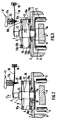
- the switching device shown in the drawing comprises an operating member 1 which comprises a contact part 2, electrically conductive, and a pusher 3, electrically insulating.
- the pusher 3 is substantially cylindrical, while the contact part 2 is in the form of a metal strip substantially rectangular.
- the contact piece 2 is able to be applied simultaneously on two contact terminals 4, 5 which have contact surfaces 4 a , 5 a , situated in the same plane parallel to the contact piece 2.
- the contact terminals 4 and 5 are each located in a housing provided for this purpose in a conductive body 6, at a distance from the wall of the housing, said terminals being electrically isolated from said body.
- the conductive body 6 comprises an electrically conductive closure plate 7 in which is formed an orifice 7 a allowing the passage of the pusher 3.
- the power line consisting of the two terminals of contact 4, 5 and the contact part 2 is thus protected from any electromagnetic radiation outside the device switching.
- the operating member 1 is integral with two parallel flexible blades 8 and 9, the shape of which general rhombus is visible in Figure 1.
- Each flexible blade is retained at each of its ends 8a, 9a in a cradle of a support 10.
- the support 10 comprises four parallel arms 10 a , each of which comprises a cradle 10 b capable of receiving the end 8a, 9a of a flexible blade 8, 9, said end being simply placed in the cradle where it is immobilized because its dimensions are very slightly smaller than those of the cradle.
- each end 8a, 9a is free to leave the cradle 10 b in which it is housed.
- pusher 3 can only move according to a movement of axial translation during which the flexible blades 8, 9 flex while remaining parallel to each other.
- Figure 2 shows the switching device in the open position of the operating member, the contact part 2 being away from contact terminals 4 and 5.
- the flexible blades 8, 9 have a natural camber that corresponds to that shown in figure 2.
- the flexible blades 8, 9 exert in permanence on pusher 3 a force directed along its axis of movement in the direction indicated by the arrow 11 in FIG. 2.
- the pusher 3 transmits this force to the contact part 2 which is thus properly applied against the plate closure 7.
- FIG. 4 represents an example of a structure making it possible to secure the flexible blades 8, 9 to the pusher 3.
- the opening of the socket 13 must be sufficiently large to allow the engagement of this one, by a movement of radial translation, on the upper part of the pusher 3.
- An internal rib 14 of the sleeve 13 is susceptible, by rotation of the sleeve 13, to cooperate with a groove 15 provided on pusher 3.
- cambered blades 8, 9 repel the pusher 3 permanently according to arrow 11, it is not useful to provide a stop between the lower part of the pusher 3 and the blade 9, the part contact 2 fulfilling this stop function by applying against the closing plate 7.
- a flexible annular membrane 16 provides a sealing between pusher 3 and closure plate 7.
- the switching device comprise no part which would be capable of producing dust by friction against another part, but also, the membrane 16 provides protection of the contact parts of the device against possible dust which could come from from the outside and enter the housing 6 through the opening 7 a .
- An actuator 17, for example electromagnetic, is likely to move along an axis parallel to that of pusher 3.
- control blade 18 is located at the near the free end of the pusher 3.
- control blade 18 is capable of transmit to pusher 3 the translational movements of the actuator 17 which are directed according to the arrow 20 indicated on the Figure 3, to bring the operating member 1 in its position closing.
- the presence of the blade of control 18 allows the use of an actuator 17 whose travel axial is slightly too large compared to that of the operation 1, which ensures optimum contact between the contact terminals 4, 5 and contact part 2.
- the tenon 23 After engagement of the pin 23 in the slot 22, the tenon 23, for example using a high frequency vibrating tool, to secure the contact part 2 and the pusher 3, as illustrated in figure 7.
- An anti-rotation link is also provided between the pusher 3 and the flexible blades, as visible in FIG. 1, in giving the pusher a section of substantially rectangular shape at the less in its connection part with the flexible blades which are provided with orifices 24 of corresponding shape.
Landscapes
- Push-Button Switches (AREA)
- Rotary Switch, Piano Key Switch, And Lever Switch (AREA)
- Switch Cases, Indication, And Locking (AREA)
Description
- la figure 1 représente en perspective un dispositif de commutation selon un mode de réalisation de l'invention, en position ouverte.
- la figure 2 est une vue en coupe selon II-II de la figure 1,
- la figure 3 est une vue analogue à la figure 2, en position fermée.
- la figure 4 représente en perspective un détail de la figure 1,
- la figure 5 est une vue en perspective et de dessous de la pièce de contact et du poussoir des deux dispositifs illustrés, et
- la figure 6 est une vue analogue à la figure 5, après assemblage de la pièce de contact et du poussoir.
Claims (6)
- Dispositif de commutation pour ouvrir et fermer une ligne électrique, comportant deux bornes de contact, un organe de manoeuvre comportant une pièce de contact, apte à être déplacé axialement entre une position de fermeture dans laquelle la pièce de contact s'applique simultanément sur les deux bornes de contact en les reliant électriquement et une position d'ouverture dans laquelle la pièce de contact est écartée des deux bornes de contact, et deux lames flexibles parallèles solidaires dudit organe de manoeuvre (1), caractérisé par le fait que la partie centrale de chaque lame flexible (8,9) est solidaire de l'organe de manoeuvre (1) et que chacune des extrémités (8a,9a) de chaque lame flexible (8,9) est logée dans un berceau (10a) d'un support (10).
- Dispositif selon la revendication 1, caractérisé par le fait qu'il comporte un actionneur (17) à déplacement axial agissant sur au moins une lame flexible de commande (18), sensiblement perpendiculaire à l'axe de déplacement de l'organe de manoeuvre (1) et apte à transmettre à ce dernier les mouvements de l'actionneur (17).
- Dispositif selon l'une quelconque des revendications 1 et 2, caractérisé par le fait qu'il comporte une plaque de fermeture (7) électriquement conductrice et que l'organe de manoeuvre (1) comporte un poussoir (3) électriquement isolant, la pièce de contact (2) de l'organe de manoeuvre (1), ainsi que les deux bornes de contact (4,5), se situant d'un côté de ladite plaque de fermeture (7), tandis que la majeure partie du poussoir (3), ainsi que les deux lames flexibles (8,9 et le support (10) se situent de l'autre côté de la plaque de fermeture (7).
- Dispositif selon la revendication 3, caractérisé par le fait que la plaque de fermeture (7) comporte un orifice (7a) permettant le passage et le déplacement axial sans frottement du poussoir (3).
- Dispositif selon la revendication 4, caractérisé par le fait qu'il comporte un moyen d'étanchéité (16) entre le poussoir (3) et la plaque de fermeture (7).
- Dispositif selon l'une quelconque des revendications 3 à 5, caractérisé par le fait qu'en position d'ouverture de l'organe de manoeuvre (1), la pièce de contact (2) s'appuie sur la plaque de fermeture (7).
Applications Claiming Priority (2)
| Application Number | Priority Date | Filing Date | Title |
|---|---|---|---|
| FR9402506A FR2717003B1 (fr) | 1994-03-04 | 1994-03-04 | Dispositif de commutation pour ouvrir et fermer une ligne électrique. |
| FR9402506 | 1994-03-04 |
Publications (2)
| Publication Number | Publication Date |
|---|---|
| EP0670579A1 EP0670579A1 (fr) | 1995-09-06 |
| EP0670579B1 true EP0670579B1 (fr) | 1999-07-21 |
Family
ID=9460681
Family Applications (1)
| Application Number | Title | Priority Date | Filing Date |
|---|---|---|---|
| EP95400468A Expired - Lifetime EP0670579B1 (fr) | 1994-03-04 | 1995-03-03 | Dispositif de commutation pour ouvrir et fermer une ligne électrique |
Country Status (5)
| Country | Link |
|---|---|
| US (1) | US5528006A (fr) |
| EP (1) | EP0670579B1 (fr) |
| JP (1) | JPH0845388A (fr) |
| DE (2) | DE69510839T2 (fr) |
| FR (1) | FR2717003B1 (fr) |
Families Citing this family (7)
| Publication number | Priority date | Publication date | Assignee | Title |
|---|---|---|---|---|
| FR2837977A1 (fr) * | 2002-03-26 | 2003-10-03 | Radiall Sa | Dispositif de commutation pour ouvrir et fermer au moins une ligne electrique |
| JP4470837B2 (ja) * | 2005-08-12 | 2010-06-02 | オムロン株式会社 | リレー |
| US20080125765A1 (en) * | 2006-11-24 | 2008-05-29 | Berenshteyn A | Microwave apparatus for ablation |
| US8343144B2 (en) * | 2008-02-11 | 2013-01-01 | Expandoheat, Llc | Apparatus and method for vessel sealing and tissue coagulation |
| CN102683079B (zh) * | 2011-03-10 | 2015-05-13 | 海洋王照明科技股份有限公司 | 一种防水开关结构及包括该防水开关结构的照明装置 |
| DE102015212817A1 (de) * | 2015-07-08 | 2017-01-12 | Te Connectivity Germany Gmbh | Kontaktbrückenanordnung für ein elektrisches Schaltelement |
| FR3041810B1 (fr) * | 2015-09-24 | 2018-11-16 | Radiall Sa | Dispositif de commutation sans frottement pour ouvrir et fermer une ligne electrique, a precision de manœuvre amelioree |
Family Cites Families (12)
| Publication number | Priority date | Publication date | Assignee | Title |
|---|---|---|---|---|
| DE35730C (de) * | E. ZELLER in Greenock, Schottland | Apparat zum Schliefsen und Unterbrechen eines elektrischen Stromkreises | ||
| US2472333A (en) * | 1945-06-04 | 1949-06-07 | Everard F Kohl | Snap acting electric switch |
| US2473970A (en) * | 1946-08-29 | 1949-06-21 | First Ind Corp | Snap acting device and electric switch |
| CH413953A (de) * | 1964-12-15 | 1966-05-31 | Inventio Ag | Verschlusseinrichtung für mindestens eine Kontaktbrücke eines Tastschalters |
| US3582594A (en) * | 1968-11-15 | 1971-06-01 | Mechanical Enterprises Inc | Actuator useable for electric switches and the like |
| US3769474A (en) * | 1971-11-29 | 1973-10-30 | Allen Bradley Co | Contact pressure sustaining switch |
| US3940578A (en) * | 1973-04-09 | 1976-02-24 | Alphameric Keyboards Limited | Keyboard structure having panel mounted key actuators with electrical component operating element |
| US3973094A (en) * | 1975-04-28 | 1976-08-03 | Allen-Bradley Company | Two-stage snap-action switch |
| US4152563A (en) * | 1976-11-29 | 1979-05-01 | B/W Controls, Inc. | Push-button reversing switch |
| DE2752638C2 (de) * | 1977-11-25 | 1986-02-20 | Schaltbau GmbH, 8000 München | Schnappschalter mit Doppelunterbrechung |
| DE3711789A1 (de) * | 1987-04-08 | 1988-10-27 | Kostal Leopold Gmbh & Co Kg | Drucktastenschalter |
| DE9010425U1 (de) * | 1990-07-11 | 1990-10-11 | Siemens AG, 8000 München | Einrichtung zum Übertragen einer Linearbewegung mit Hilfe eines Tastelements |
-
1994
- 1994-03-04 FR FR9402506A patent/FR2717003B1/fr not_active Expired - Fee Related
-
1995
- 1995-03-03 US US08/398,601 patent/US5528006A/en not_active Expired - Lifetime
- 1995-03-03 DE DE69510839T patent/DE69510839T2/de not_active Expired - Lifetime
- 1995-03-03 EP EP95400468A patent/EP0670579B1/fr not_active Expired - Lifetime
- 1995-03-03 DE DE0670579T patent/DE670579T1/de active Pending
- 1995-03-06 JP JP7084462A patent/JPH0845388A/ja active Pending
Also Published As
| Publication number | Publication date |
|---|---|
| FR2717003A1 (fr) | 1995-09-08 |
| EP0670579A1 (fr) | 1995-09-06 |
| DE69510839T2 (de) | 2000-03-16 |
| JPH0845388A (ja) | 1996-02-16 |
| FR2717003B1 (fr) | 1996-04-12 |
| DE670579T1 (de) | 1996-05-02 |
| US5528006A (en) | 1996-06-18 |
| DE69510839D1 (de) | 1999-08-26 |
Similar Documents
| Publication | Publication Date | Title |
|---|---|---|
| CA1202654A (fr) | Relais coaxial inverseur hyperfrequence | |
| EP1054479A1 (fr) | Dispositif pour relier électriquement une ligne coaxiale à une carte de circuit imprimé | |
| EP1028490A1 (fr) | Raccord coaxial pour relier deux cartes de circuit imprimé | |
| FR2727806A1 (fr) | Dispositif de protection a l'encontre de surtensions transitoires a base de varistances et deconnecteurs thermiques | |
| EP1139367B1 (fr) | Module de coupure comportant une ampoule à vide et des moyens de fixation, et appareillage electrique de coupure comportant un tel module | |
| FR2734398A1 (fr) | Commutateur electrique a actionnement lateral | |
| EP1213792B1 (fr) | Connecteur de raccordement bistable | |
| FR2771846A1 (fr) | Commutateur electrique a effet tactile a plusieurs voies et a organe de declenchement unique | |
| EP0670579A1 (fr) | Dispositif de commutation pour ouvrir et fermer une ligne électrique | |
| EP0358562B1 (fr) | Boitier de connecteur blindé | |
| EP0570264A1 (fr) | Sectionneur à ouverture verticale et colonne oscillante | |
| FR2545283A1 (fr) | Dispositif de contact | |
| FR3053523A1 (fr) | Commutateur electrique a positions multiples | |
| EP1349187B1 (fr) | Dispositif de commutation pour ouvrir et fermer au moins une ligne électrique | |
| FR2937175A1 (fr) | Appareil de commutation electrique muni de deux interrupteurs, tels qu'un sectionneur de barre et un sectionneur de terre et comprenant des moyens d'entrainement communs des contacts mobiles des interrupteurs. | |
| CH705205B1 (fr) | Sectionneur de terre à encombrement réduit. | |
| WO1999065374A1 (fr) | Appareil electrique de cuisson a cuve amovible | |
| FR2532485A1 (fr) | Pince pour le sertissage d'un raccord a piston sur un cable auto-porteur | |
| EP0209433A1 (fr) | Pièce de support de contacts mobiles, notamment pour appareil interrupteur de protection | |
| FR3041810A1 (fr) | Dispositif de commutation sans frottement pour ouvrir et fermer une ligne electrique, a precision de manœuvre amelioree | |
| EP1672740B1 (fr) | Borne de connexion rapide pour interrupteurs et prises de courant | |
| EP0074061B1 (fr) | Borne modulaire de raccordement électrique | |
| EP0113734A1 (fr) | Interrupteur electrique a ressort de contact prearme | |
| FR2789809A1 (fr) | Bloc de jonction comportant un dispositif de contact sectionnable | |
| FR2789810A1 (fr) | Bloc de jonction comportant un dispositif de contact sectionnable |
Legal Events
| Date | Code | Title | Description |
|---|---|---|---|
| PUAI | Public reference made under article 153(3) epc to a published international application that has entered the european phase |
Free format text: ORIGINAL CODE: 0009012 |
|
| AK | Designated contracting states |
Kind code of ref document: A1 Designated state(s): DE FR GB IT SE |
|
| 17P | Request for examination filed |
Effective date: 19950916 |
|
| ITCL | It: translation for ep claims filed |
Representative=s name: SOCIETA' ITALIANA BREVETTI S.P.A. |
|
| GBC | Gb: translation of claims filed (gb section 78(7)/1977) | ||
| DET | De: translation of patent claims | ||
| GRAG | Despatch of communication of intention to grant |
Free format text: ORIGINAL CODE: EPIDOS AGRA |
|
| 17Q | First examination report despatched |
Effective date: 19981116 |
|
| GRAG | Despatch of communication of intention to grant |
Free format text: ORIGINAL CODE: EPIDOS AGRA |
|
| GRAH | Despatch of communication of intention to grant a patent |
Free format text: ORIGINAL CODE: EPIDOS IGRA |
|
| GRAH | Despatch of communication of intention to grant a patent |
Free format text: ORIGINAL CODE: EPIDOS IGRA |
|
| GRAA | (expected) grant |
Free format text: ORIGINAL CODE: 0009210 |
|
| AK | Designated contracting states |
Kind code of ref document: B1 Designated state(s): DE FR GB IT SE |
|
| REF | Corresponds to: |
Ref document number: 69510839 Country of ref document: DE Date of ref document: 19990826 |
|
| GBT | Gb: translation of ep patent filed (gb section 77(6)(a)/1977) |
Effective date: 19990922 |
|
| ITF | It: translation for a ep patent filed | ||
| PLBE | No opposition filed within time limit |
Free format text: ORIGINAL CODE: 0009261 |
|
| STAA | Information on the status of an ep patent application or granted ep patent |
Free format text: STATUS: NO OPPOSITION FILED WITHIN TIME LIMIT |
|
| 26N | No opposition filed | ||
| REG | Reference to a national code |
Ref country code: GB Ref legal event code: IF02 |
|
| PGFP | Annual fee paid to national office [announced via postgrant information from national office to epo] |
Ref country code: DE Payment date: 20120223 Year of fee payment: 18 |
|
| PGFP | Annual fee paid to national office [announced via postgrant information from national office to epo] |
Ref country code: SE Payment date: 20120224 Year of fee payment: 18 Ref country code: GB Payment date: 20120224 Year of fee payment: 18 Ref country code: IT Payment date: 20120225 Year of fee payment: 18 |
|
| REG | Reference to a national code |
Ref country code: SE Ref legal event code: EUG |
|
| PG25 | Lapsed in a contracting state [announced via postgrant information from national office to epo] |
Ref country code: SE Free format text: LAPSE BECAUSE OF NON-PAYMENT OF DUE FEES Effective date: 20130304 |
|
| GBPC | Gb: european patent ceased through non-payment of renewal fee |
Effective date: 20130303 |
|
| REG | Reference to a national code |
Ref country code: DE Ref legal event code: R119 Ref document number: 69510839 Country of ref document: DE Effective date: 20131001 |
|
| PG25 | Lapsed in a contracting state [announced via postgrant information from national office to epo] |
Ref country code: GB Free format text: LAPSE BECAUSE OF NON-PAYMENT OF DUE FEES Effective date: 20130303 Ref country code: DE Free format text: LAPSE BECAUSE OF NON-PAYMENT OF DUE FEES Effective date: 20131001 |
|
| PG25 | Lapsed in a contracting state [announced via postgrant information from national office to epo] |
Ref country code: IT Free format text: LAPSE BECAUSE OF NON-PAYMENT OF DUE FEES Effective date: 20130303 |
|
| PGFP | Annual fee paid to national office [announced via postgrant information from national office to epo] |
Ref country code: FR Payment date: 20140328 Year of fee payment: 20 |