EP0669014B1 - Elektronische steuereinrichtung - Google Patents
Elektronische steuereinrichtung Download PDFInfo
- Publication number
- EP0669014B1 EP0669014B1 EP94924208A EP94924208A EP0669014B1 EP 0669014 B1 EP0669014 B1 EP 0669014B1 EP 94924208 A EP94924208 A EP 94924208A EP 94924208 A EP94924208 A EP 94924208A EP 0669014 B1 EP0669014 B1 EP 0669014B1
- Authority
- EP
- European Patent Office
- Prior art keywords
- clock
- control device
- individual
- counter
- register
- Prior art date
- Legal status (The legal status is an assumption and is not a legal conclusion. Google has not performed a legal analysis and makes no representation as to the accuracy of the status listed.)
- Expired - Lifetime
Links
- 238000002347 injection Methods 0.000 claims description 37
- 239000007924 injection Substances 0.000 claims description 37
- 238000000034 method Methods 0.000 claims description 6
- 230000008569 process Effects 0.000 claims description 6
- 238000000605 extraction Methods 0.000 claims 1
- 238000003780 insertion Methods 0.000 claims 1
- 230000037431 insertion Effects 0.000 claims 1
- 230000009471 action Effects 0.000 abstract description 6
- 238000011156 evaluation Methods 0.000 abstract description 5
- 238000010586 diagram Methods 0.000 description 13
- 238000002485 combustion reaction Methods 0.000 description 7
- 230000001419 dependent effect Effects 0.000 description 7
- 230000008859 change Effects 0.000 description 5
- 230000006870 function Effects 0.000 description 3
- 230000002123 temporal effect Effects 0.000 description 3
- 230000001960 triggered effect Effects 0.000 description 2
- 230000008901 benefit Effects 0.000 description 1
- 230000015572 biosynthetic process Effects 0.000 description 1
- 125000004122 cyclic group Chemical group 0.000 description 1
- 230000005611 electricity Effects 0.000 description 1
- 230000005670 electromagnetic radiation Effects 0.000 description 1
- 238000005516 engineering process Methods 0.000 description 1
- 238000005562 fading Methods 0.000 description 1
- 239000000446 fuel Substances 0.000 description 1
- 230000000737 periodic effect Effects 0.000 description 1
- 230000036316 preload Effects 0.000 description 1
- 239000000243 solution Substances 0.000 description 1
- 230000007704 transition Effects 0.000 description 1
Images



Classifications
-
- F—MECHANICAL ENGINEERING; LIGHTING; HEATING; WEAPONS; BLASTING
- F02—COMBUSTION ENGINES; HOT-GAS OR COMBUSTION-PRODUCT ENGINE PLANTS
- F02D—CONTROLLING COMBUSTION ENGINES
- F02D41/00—Electrical control of supply of combustible mixture or its constituents
- F02D41/24—Electrical control of supply of combustible mixture or its constituents characterised by the use of digital means
- F02D41/2403—Electrical control of supply of combustible mixture or its constituents characterised by the use of digital means using essentially up/down counters
-
- G—PHYSICS
- G04—HOROLOGY
- G04G—ELECTRONIC TIME-PIECES
- G04G15/00—Time-pieces comprising means to be operated at preselected times or after preselected time intervals
-
- G—PHYSICS
- G04—HOROLOGY
- G04G—ELECTRONIC TIME-PIECES
- G04G3/00—Producing timing pulses
Definitions
- the invention relates to an electronic control device according to the genus of the main claim. Let such electronic control devices use themselves to solve a variety of tasks. An action, especially a tax function, is depending on the meter reading of a meter carried out. This action can then, for example when the counter counts or when it counts has reached a certain counter reading.
- the counter is connected to a clock source that the counter specifies the counting clock.
- the area of application of the known electronic control devices is due limited relatively rigidly specified possibilities.
- the injection counter can with a preload value that was previously in a Cache is saved.
- the object is achieved Specify control device in which both the duration and also the start time of an injection Registered mail to be specified.
- the control device Has the advantage that both the start time of the counter depending on desired parameters as well the counting interval also depending on desired parameters - variable and always in each case to a desired value during operation is adjustable again, so that while running Operating currently affect the control functions can be taken.
- a controlled by the control device Establishment depending on the above Parameters can be operated optimally.
- the electronic control device suitable for the operation of an internal combustion engine, preferably around an injection control and to realize an ignition control. With the injection control is dependent the crankshaft angle and other parameters the start of injection and the duration of injection to realize.
- the counter first register in which a first, specifiable, in particular changeable register value can be registered by means of a charging device to set as the current counter reading Counter can be fed and the loading device an event device is assigned which is dependent the predeterminable occurrence of an event the setting of the Triggers by starting the charging device
- the functions mentioned can be optimally implemented.
- the injection duration depending on the in the first register of the registered register value the injection duration can be adjusted accordingly.
- the Injection takes place with the start of the counter and ends when it reaches a certain counter reading Has.
- the counter is only started then when the event facility is dependent the predeterminable occurrence of an event Set the counter by starting the charging device triggers.
- the first register value of the first register by means of the Charger supplied to the meter, which then with a counter reading corresponding to the register value starts.
- the time of injection determine. Because an influence insists on the occurrence of the event and also the register value and thus the counting time of the Counter can be varied - can be mentioned in the Automotive injection control example injection timing and injection duration the constantly changing Operating conditions when driving a Be adapted to the vehicle.
- the event facility points at least one comparator, the one second, predeterminable, in particular changeable register value a second register with the value of a Clock facility compares, and that entry of the event due to the identity of the second register value with the value of the clock device he follows.
- the clock device can for example go through periodic clock cycles, so that whenever the second register value is identical to the data of a specific cycle cycle is the comparator determines this equality and thus triggers the event signal. Since the second register value is changeable Take current conditions into account.
- the clock source has a constant time base having.
- the Contact source designed as an asynchronous source is.
- a "constant time base" means that equidistante There are intervals between the clock pulses.
- the clock period is for asynchronous sources different lengths.
- the clock source has multiple individual clock sources and that the clock of the clock source by by means of a first selection device Choice of one of the single clock sources provided on the meter becomes. It is therefore possible to choose one of multiple clock sources to select the counting clock of the counter. Change operational circumstances, another single clock source can be selected be, whereby a corresponding change of the Counting clock takes place.
- the clock source has multiple single clock sources with one first multiplex device cooperate and that at the multiplexed clock output of the first multiplex device by means of a first time selection device the clock of one of the single clock sources selected and fed to the meter.
- the clock source consists of several individual clock sources the difference that all single clock sources interact with the first multiplex device, so that on the multiplexed clock output the clock signals to the first multiplex device all single clock sources provided become.
- the first time selection device is then from the large number of bars on multiplexed clock output selected the clock that to be fed to the meter.
- the first time selection device preferably has a first AND gate, with an input of the first And elements to the multiplexed clock output the first multiplex device is connected. Another entrance of the first AND gate is a first selection signal for a temporal selection of the clock fed. Is the first selection signal at the entrance of the AND link, so an am clock arriving at the other input of the AND gate transferred to the output of the first AND gate and fed to the counter.
- the first register has multiple individual registers has and that by means of a second selection device one of the individual registers for provision of the first register value can be selected.
- a second selection device one of the individual registers for provision of the first register value can be selected.
- the counter different To supply start values.
- In the first single register are these different starting values registered, where only the register value of the selected Single registers the counter upon entry of the event.
- the clock device has several individual clock devices and if the clock by means of a fourth selection device choice of one of the individual clock devices provided on the comparator becomes. This is a variation of the clock data Clock setup possible. It can be the single clock device can be selected that are aimed at Best solution to the current task suitable is.
- the clock device may have several Has single-clock devices with a second multiplex device cooperate and that the multiplexed clock output of the second Multiplex device using a second Time selection device the clock of one of the individual clock devices selected and fed to the comparator becomes.
- the second multiplex device At the exit of the second multiplex device are all the bars of the individual clock devices where the measure used by means of the time selection device from this Clock variety is selected.
- the second time selection device preferably one have second AND gate, with an input of second AND gate on the multiplexed clock output connected to the second multiplex device is. Another entrance of the second AND gate becomes a second output signal for a temporal selection of the clock to be used, where the output of the second AND gate to Feeding the selected clock to the comparator connected.
- the clock device has several individual clock devices, each at an input of a comparator are connected to a second input each comparator supplied the second register value and that by means of a fifth selection device made by one of the comparators the event signal is provided.
- a fifth selection device made by one of the comparators the event signal is provided.
- Dependence on the coincidence of the data value of the second register and the data of the individual clock devices is thus on the corresponding comparator issued a signal to the fifth selection device reached.
- One of these signals is by means of the fifth selection facility selected to do that Form event signal.
- the clock device has several individual clock devices, the with a third multiplex device cooperate, that preferably over a multiplex clock data bus to the multiplexed clock output of the third multiplex device an input of the comparator connected is that preferably over a clock address bus an address selection circuit the addresses the clock data of the individual clock devices supplied and that by means of a sixth selection device the output of the comparator Delivery of the event signal is switched through. Due to the third multiplex setup the clocks of all individual clock devices at its output to disposal. These arrive an input of the comparator. At the other entrance the second register value is applied to the comparator. Identity is at the inputs of the comparator before, the comparator gives an output signal the sixth selection facility. Of the multitude this comparator output signals is by means of sixth selection device one as an event signal selected.
- the sixth selection device preferably has a third AND gate, with an input of the third AND gate to the output of the comparator and another input of the third AND gate the address selection circuit is connected.
- the address selection circuit givess the address selection circuit when a specific address an output signal to the input of the third AND element and lies at the same time an output signal from the comparator before, so the event signal at the output of the third AND gate spent. That of the address selection circuit supplied addresses come from the individual clock devices, that is, every cycle of each individual clock device an address is assigned.
- the data of the clock address bus is preferred in time before the data of the associated individual clock device transmitted from the multiplex clock data bus. This will decode the clock device selection staggered to the corresponding Data made. Through this pipelining structure a higher clock rate is possible.
- the address of the cycle data just like the clock data itself, the individual clock devices transmitted on the multiplex clock data bus are, the addresses before the Clock data are transmitted and a memory for the addresses is provided. This saves at Variety of individual clocks the number of Address lines. However, this will make the maximum Counting speed reduced. So that the respective Address when the clock data arrives is available is the memory mentioned available.
- the clock source and / or the clock device in each case one device for programmable fading in or out of data bits.
- the motor vehicle control necessary 720 ° of a crankshaft engine cycle with the same clock device (angular source) also as a 360 ° crankshaft position interpret.
- the clock source and / or the clock device can be designed as a time device (timer). It however, it is also possible that the clock source and / or the clock device is designed as an angle encoder is.
- the clock source and / or the clock device however, can be done in other ways be realized, for example always one Make a beat when a certain situation arises.
- Figure 1 shows a block diagram of an electronic Control device 1.
- a clock source TQ is connected to a counter Z.
- the clock source TQ determines the counter clock of counter Z.
- a counter reading evaluation unit ZA is connected to the output of the counter Z.
- ZA On the output of the counter Z is a counter reading evaluation unit ZA connected.
- FIG first register R1 shown, in which a first, specifiable, in particular changeable register value is enrollable.
- the register value is from Depends on parameters to be controlled from the System. Alternatively, it is also possible that a fixed, so unchangeable value is stored in the first register R1.
- the register value of the register R1 becomes a loader L fed.
- This loading device L loads the first register value into the counter Z if an event signal from an event device E. ES is supplied to the charging device L. this leads to cause the counter Z to the first register value is set as the counter start value.
- Dependent on the counter counts from the clock of the clock source TQ - starting from this counter reading to a certain one Final meter reading is reached. It is possible, that the counter counts down and that the end of the counter has the value zero. However, it can also another non-zero counter reading be provided. When this final meter reading is reached, so this is done by the counter reading evaluation unit ZA registered and the action signal AK spent. Alternatively, it is of course also possible that the counter counts up, that is, the Initial counter status (value of the first register) less than the final meter reading.
- the event device E outputs the event signal ES to the charger L, which then by writing the first register value into the Counter as counter start value starts the counter.
- the Occurrence of the event is also of corresponding Parameters of the process to be controlled.
- the control device 1 of FIG. 1 can, for example in an injection module in automotive engineering Find use. Whenever a certain crankshaft angle of an internal combustion engine the event occurs, that is, the event device E outputs the event signal ES to the loading device L. This is the Start of injection relative to the crankshaft angle fixed. Do the operating parameters change Internal combustion engine, so the time of the start of injection, so the occurrence of the event, be appropriately varied. In the first register R1 becomes dependent on the operating parameters of the Internal combustion engine - a value inscribed that corresponds to the injection duration. This value too can during the operation of the internal combustion engine to be changed.
- FIG. 2 shows a block diagram of the event device E. It has a clock device TE and a second register R2.
- the second register R2 can be a second definable, in particular Register changeable register value.
- This second register value is sent to input B of a comparator K.
- the output of the clock device TE has another entrance A of the comparator K in connection. Is at the entrances A and B of the comparator K are identical Value, the comparator gives K at its output the event signal ES.
- TE can be an angle encoder act, the angular value of the respective crankshaft position corresponds.
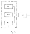
- FIG. 3 shows a block diagram of the clock source TQ. It consists of several individual clock sources TQ1, TQ2, TQ3 etc. together.
- the clock data of the individual clock sources TQ1, TQ2, TQ3 become one first selection device AE1 supplied.
- Dependent on of parameters of the process to be controlled the first selector AE1 selects one of the Single clock sources TQ1, TQ2, TQ3, whose clock the counter Z is supplied. Because of the variety the individual clock sources TQ1, TQ2, TQ3 can thus the counting frequency of the counter Z in the desired Influence wise.
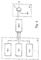
- FIG 4 shows a further embodiment a clock source TQ.
- the multiplexed clock output of the first Multiplexing device MUX1 is connected to a time selection device ZT1 connected.
- the Time selection device ZT1 the clock data of those Single clock source TQ, TQ2, TQ3 selects that should be sent to the meter. So is also a selection of the in this embodiment Clock frequency possible.
- the time selection device ZT1 of FIG. 4 has a first AND gate 2. An entrance to this first And gate 2 is on the multiplexed clock output the first multiplex device MUX1 connected. A second entrance of the first AND gate can be supplied with a first selection signal AS1 become. This is a time selection of the desired cycle possible. Whenever the desired clock at the one input of the AND gate is applied, this is created by creating the first Selection signal AS1 to the output of the first AND gate 2 transmitted and can thus be fed to the counter Z. become.
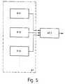
- the first register R1 can have several have first individual registers R11, R12, R13 etc.
- the outputs of all the first individual registers R11, R12, R13 are connected to a second selection device AE2 connected. This is from the corresponding Influenced parameters of the process to be controlled and thus enables one of the first individual registers Select R11, R12, R13 so that its value supplied to the counter Z by the charging device as soon as an event signal is present.
- Figure 6 illustrates that the second register R2 several second individual registers R21, R22, R23, etc. may have a third selection device AE3 are connected.
- the third Selection device AE3 enables the selection of one the second individual registers R21, R22, R23, see above that the corresponding second register value of the selected one second individual register the comparator K is feedable.
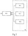
- the formation of the clock device TE explained in more detail. It has several individual clock devices TE1, TE2, TE3 etc. on the connected to a fourth selection device AE4 are.
- this fourth selection device AE4 can make a choice between the individual clock devices TE1, TE2, TE3 take place, that is, the clock of the selected individual clock device is fed to the comparator K. Because of the variety the individual clock devices TE1, TE2, TE3 make individual settings.
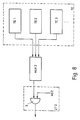
- FIG. 8 illustrates using a block diagram another embodiment of a clock device TE.
- This in turn has several individual clock devices TE1, TE2, TE3 etc. on the connected to a second multiplex device MUX2 are.
- the multiplexed clock output of the second multiplex device MUX2 is available with a second time selection device ZT2 in connection.
- This selects from the large number of clock data of the individual clock device TE1, TE2, TE3 on multiplexed Clock output of the second multiplex device MUX2 the desired clock data of the selected individual clock device out.
- the second one Time selection device ZT2 a second AND gate 3 at whose one entrance the multiplexed Clock output of the second multiplex device MUX2 connected.
- Another entrance to the second And gate 3 becomes a second selection signal AS2 for a temporal selection of the desired one Fed clock.
- the corresponding clock to the output of the AND gate passed on and fed to the comparator K.
- the clock device TE several individual clock devices TE1, TE2, TE3, etc., each connected to the A input of a Comparators K1, K2, K3 etc. are connected.
- the second input B of the individual comparators K1, K2, K3 is connected to the output of the second register.
- the outputs of the comparators K1, K2, K3 are fed to a fifth selection device AE5.
- the comparators switch K1, K2, K3 and give their output signal to the fifth selection device AE5.
- This selects operating parameters that can be predetermined from the multitude of output signals from the comparators K1, K2, K3 a corresponding output signal and outputs this as an event signal ES to the Loading device L from.
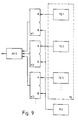
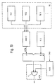
- the clock device TE has several Single clock devices TE1, TE2, TE3 etc. on to a third multiplex device MUX3 are connected.
- the multiplexed clock output the third multiplex device MUX3 is over a multiplex clock data bus MTB with the A input of the comparator K in connection.
- the B entrance of the Comparator K is at the output of the second register R2 connected.
- the output of the comparator K stands with a sixth selection device AE6 in connection, the output of which is the event signal ES delivers.
- the sixth selection device AE6 points a third AND gate 4, at the one entrance the output of the comparator K is connected is.
- Another input of the third AND gate 4 is connected to an address selection circuit AAS.
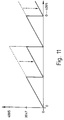
- Figure 11 illustrates the practical application an injection module that by inclusion Hide bits of the clock data the clock device TE has a current data value part of a cycle can be projected.
- the number of a twelve-bit clock for example an angle between 0 ° and 720 ° (the means two revolutions) of the crankshaft, so can by hiding a bit (then there are only still eleven bits available) the values of the second Revolution always projected onto the first revolution become.
- the necessary in the motor vehicle control 720 ° of a crankshaft engine cycle can do so with the same angle source also as a 360 ° crankshaft position be interpreted.
- Figure 11 corresponds the number 4095 the twelve bit value and the Number 2047 the eleven bit value.
- the device according to the invention thus represents a Structure for mixed digital processing of various electronic databases, for example Timebase and / or angular basis available for example in automotive injection technology can be used.
- the module compares depending on the initial state a value of the second register R2 with the Crankshaft angle (timing device TE). With identity an output signal is set or deleted and thus triggered an ignition, if a falling edge of the output signal (Ignition angle) is present.
- the ignition is - as described above - with identity at a corresponding start angle switched on, but after an im first register R1 standing opening angle turned off.
- the in the first register standing first register value with the clock of the clock source decremented.
- Injection module compares this to a value in the second register with the crankshaft angle (clock device TE).
- identity the content of the first register loaded in the counter and with a Time count down from, for example, 1 microsecond (Clock source).
- Lock source the content of the first register loaded in the counter and with a Time count down from, for example, 1 microsecond (Clock source).
- Becomes the next identity the value of the second register with the clock device detects before the meter reaches its final meter reading, for example, has reached zero the counter again with the value of the first register loaded (continuous transition from injection to continuous wave and back).
- the state of the counter (count status or reaching of the final count) corresponds to the output signal for the injection valve (opening begins as an angle base, Opening time as time base).
- a complete one Loading process from opening and opening time can be made even while the execution of the last cycle runs since the data is up to their use can be overwritten as often as required.
- An injection that has already been triggered can be caused by direct change of the meter reading at any time lengthened or shortened, for example by writing a value into one already counter counted to zero, resulting in a Post-injection is achieved.
Landscapes
- Engineering & Computer Science (AREA)
- Physics & Mathematics (AREA)
- General Physics & Mathematics (AREA)
- Mechanical Engineering (AREA)
- General Engineering & Computer Science (AREA)
- Chemical & Material Sciences (AREA)
- Combustion & Propulsion (AREA)
- Manipulation Of Pulses (AREA)
- Electric Clocks (AREA)
- Measurement Of Predetermined Time Intervals (AREA)
- Electrical Control Of Air Or Fuel Supplied To Internal-Combustion Engine (AREA)
- Measurement Of Unknown Time Intervals (AREA)
- Time-Division Multiplex Systems (AREA)
Abstract
Description
- Figur 1
- ein Blockschaltbild der Steuereinrichtung,
- Figur 2
- ein Blockschaltbild zur Bildung eines Ereignissignals,
- Figur 3
- ein Blockschaltbild einer Taktquelle,
- Figur 4
- ein weiteres Ausführungsbeispiel einer Taktquelle,
- Figur 5
- ein Blockschaltbild eines ersten Registers,
- Figur 6
- ein Blockschaltbild eines zweiten Registers,
- Figur 7
- ein Blockschaltbild einer Takt-Einrichtung,
- Figur 8
- ein Blockschaltbild eines weiteren Ausführungsbeispiels einer Takt-Einrichtung,
- Figur 9
- ein Blockschaltbild eines weiteren Ausführungsbeispiels einer Takt-Einrichtung,
- Figur 10
- ein letztes Ausführungsbeispiel einer Takt-Einrichtung und
- Figur 11
- ein Diagramm für einen Anwendungsfall der Steuereinrichtung.
Claims (22)
- Elektronische Steuereinrichtung zur Steuerung der Einspritzdauer und des Startpunktes einer Motoreinspritzung,wobei zur Steuerung der Einspritzdauer ein erstes Register R1, ein Zähler Z und eine Ladevorrichtung L vorgesehen sind,wobei ein Zähltakt des Zähler Z durch eine Taktquelle TQ vorgegeben wird,wobei für die Einspritzdauer in das erste Register R1 ein veränderlicher Registerwert einschreibbar ist, der beim Eintreffen eines Ereignissignals ES an einem Eingang der Ladevorrichtung L von der Ladevorrichtung als Startwert in den Zähler eingeschrieben und dabei der Zähler gestartet und die Einspritzung begonnen wird,und wobei der Zähler bei Erreichen eines vorgegebenen Zählerstandes gestoppt und die Einspritzung beendet wird,wobei zur Steuerung des Startpunktes eine Ereignisvorrichtung E vorgesehen ist, die einen Ausgang zur Abgabe des Ereignissignals ES aufweist, dadurch gekennzeichnet,daß die Ereignisvorrichtung E ein zweites Register R2 eine Takt-Einrichtung TE und einen Komparator aufweist unddaß der Komparator einen in das zweite Register R2 eingeschriebenen Registerwert mit einem Wert der Takteinrichtung TE vergleicht, und bei einer Übereinstimmung der beiden Werte ein Signal zur Erzeugung des Ereignissignals ES erzeugt.
- Steuereinrichtung nach einem der vorhergehenden Ansprüche, dadurch gekennzeichnet, daß der Zähler (Z) aufwärts zählt.
- Steuereinrichtung nach einem der vorhergehenden Ansprüche 1 oder 2, dadurch gekennzeichnet, daß der Zähler (Z) abwärts zählt.
- Steuereinrichtung nach einem der vorhergehenden Ansprüche, dadurch gekennzeichnet, daß der vorgebbare Zählerendstand der Wert Null ist.
- Steuereinrichtung nach einem der vorhergehenden Ansprüche, dadurch gekennzeichnet, daß die Taktquelle (TQ) eine konstante Zeitbasis aufweist.
- Steuereinrichtung nach einem der vorhergehenden Ansprüche 1-4, dadurch gekennzeichnet, daß die Taktquelle (TQ) als asynchrone Quelle ausgebildet ist.
- Steuereinrichtung nach einem der vorhergehenden Ansprüche, dadurch gekennzeichnet, daß die Taktquelle (TQ) mehrere Einzel-Taktquellen (TQ1, TQ2, TQ3) aufweist, und daß der Takt der Taktquelle (TQ) durch mittels einer ersten Auswahl-Einrichtung (AE1) erfolgenden Wahl von einer der Einzel-Taktquellen (TE1, TE2, TE3) am Zähler (Z) bereitgestellt wird.
- Steuereinrichtung nach einem der vorhergehenden Anspruche 1-6, dadurch gekennzeichnet, daß die Taktquelle (TQ) mehrere Einzel-Taktquellen (TQ1, TQ2, TQ3) aufweist, die mit einer ersten Multiplex-Einrichtung (MUX1) zusammenwirken, und daß an den gemultiplexten Taktausgang der ersten Multiplex-Einrichtung (MUX1) mittels einer ersten Zeitauswahl-einrichtung (ZT1) der Takt einer der Einzel-Taktquellen (TQ1, TQ2, TQ3) ausgewählt und dem Zähler (Z) zugeführt wird.
- Steuereinrichtung nach Anspruch 8, dadurch gekennzeichnet, daß die erste Zeitauswahleinrichtung (ZT1) ein erstes Und-Glied aufweist, das ein Eingang des ersten Und-Glieds an den gemultiplexten Taktausgang der ersten Multiplex-Einrichtung (MUX1) angeschlossen ist, daß einem weiteren Eingang des ersten Und-Glieds ein erstes Auswahlsignal (AS1) für eine zeitliche Auswahl des Taktes zugeführt wird, und daß der Ausgang des ersten Und-Glieds zur Zuführung des ausgewählten Takts an den Zähler (Z) angeschlossen ist.
- Steuereinrichtung nach einem der vorhergehenden Ansprüche, dadurch gekennzeichnet, daß das erste Register (R1) mehrere erste Einzel-Register (R11, R12, R13) aufweist, und daß mittels einer zweiten Auswahl-Einrichtung (AE2) eines der ersten Einzel-Register (R11, R12, R13) zur Bereitstellung des ersten Registerwerts auswählbar ist.
- Steuereinrichtung nach einem der vorhergehenden Ansprüche, dadurch gekennzeichnet, daß das zweite Register (R2) mehrere zweite Einzel-Register (R21, R22, R23) aufweist, und daß der zweite Registerwert durch mittels einer dritten Auswahl-Einrichtung (AE3) erfolgenden Wahl von einem der zweiten Einzel-Register (R21, R22, R23) am Komparator (K) bereitgestellt wird.
- Steuereinrichtung nach einem der vorhergehenden Ansprüche, dadurch gekennzeichnet, daß die Takt-Einrichtung (TE) mehrere Einzel-Takteinrichtungen (TE1, TE2, TE3) aufweist, und daß der Takt der Takt-Einrichtung (TE) durch mittels einer vierten Auswahl-Einrichtung (AE4) erfolgenden Wahl von einer der Einzel-Takteinrichtungen (TE1, TE2, TE3) am Komparator (K) bereitgestellt wird.
- Steuereinrichtung nach einem der Ansprüche 1 bis 11, dadurch gekennzeichnet, daß die Takt-Einrichtung (TE) mehrere Einzel-Takteinrichtungen (TE1, TE2, TE3) aufweist, die mit einer zweiten Multiplex-Einrichtung (MUX2) zusammenwirken, und daß an den gemultiplexten Taktausgang der zweiten Multiplex-Einrichtung (MUX2) mittels einer zweiten Zeitauswahleinrichtung (ZT2) der Takt einer der Einzel-Takteinrichtungen (TE1, TE2, TE3) ausgewählt und dem Komparator (K) zugeführt wird.
- Steuereinrichtung nach Anspruch 13, dadurch gekennzeichnet, daß die zweite Zeitauswahleinrichtung (ZT2) ein zweites Und-Glied aufweist, daß ein Eingang des zweiten Und-Glieds an den gemultiplexten Taktausgang der zweiten Multiplex-Einrichtung (MUX2) angeschlossen ist, daß einem weiteren Eingang des zweiten Und-Glieds ein zweites Auswahlsignal (AS2) für eine zeitliche Auswahl des Takts zugeführt wird, und daß der Ausgang des zweiten Und-Glieds zur Zuführung des ausgewählten Takts an den Komparator (K) angeschlossen ist.
- Steuereinrichtung nach einem der vorhergehenden Ansprüche 1 bis 11, dadurch gekennzeichnet, daß die Takt-Einrichtung (TE) mehrere Einzel-Takteinrichtungen (TE1, TE2, TE3) aufweist, daß jede Einzel-Takteinrichtung (TE1, TE2, TE3) an jeweils einen Eingang jeweils eines Komparators (K) angeschlossen ist, daß einem zweiten Eingang jedes Komparators (K) der zweite Registerwert zugeführt wird, und daß durch mittels einer fünften Auswahl-Einrichtung (AE5) erfolgenden Wahl von einem der Komparatoren (K) das Ereignissignal (ES) bereitgestellt wird.
- Steuereinrichtung nach einem der vorhergehenden Anspruche 1 bis 11, dadurch gekennzeichnet, daß die Takt-Einrichtung (TE) mehrere Einzel-Takteinrichtungen (TE1, TE2, TE3) aufweist, die mit einer dritten Multiplex-Einrichtung (MUX3) zusammenwirken, daß vorzugsweise über einen Multiplex-Taktdaten-Bus (MTB) an den gemultiplexten Taktausgang der dritten Multiplex-Einrichtung (MUX3) ein Eingang des Komparators (K) angeschlossen ist, daß vorzugsweise über einen Takt-Adress-Bus (TAB) einer Adressauswahlschaltung (AAS) die Adressen der Taktdaten der Einzel-Takteinrichtungen (TE1, TE2, TE3) zugeführt wird, und daß mittels einer sechsten Auswahl-Einrichtung (AE6) der Ausgang des Komparators (K) zur Abgabe des Ereignissignals (ES) durchgeschaltet wird.
- Steuereinrichtung nach Anspruch 16, dadurch gekennzeichnet, daß die sechste Auswahl-Einrichtung (AE6) ein drittes Und-Glied aufweist, daß ein Eingang des dritten Und-Glieds an den Ausgang des Komparators (K) und ein weiterer Eingang des dritten Und-Glieds an die Adressauswahlschaltung (AAS) angeschlossen ist, und daß am Ausgang des dritten Und-Glieds das Ereignissignal (ES) ausgegeben wird.
- Steuereinrichtung nach Anspruch 16 oder 17, dadurch gekennzeichnet, daß die Daten der Einzel-Takteinrichtungen (TE1, TE2,TE3) nur dann auf den gemeinsamen Multiplex-Taktdaten-Bus (MTB) gegeben werden, wenn sich Daten einer der Einzel-Takteinrichtungen (TE1, TE2, TE3) verändert haben oder wenn eine Anforderung erfolgt.
- Steuereinrichtung nach einem der Ansprüche 16 bis 18, dadurch gekennzeichnet, daß die Daten des Takt-Adress-Busses (TAB) zeitlich vor den Daten der zugehörigen Einzel-Takteinrichtung (TE1, TE2, TE3) vom Multiplex-Taktdaten-Bus (MTB) übertragen werden.
- Steuereinrichtung nach einem der Ansprüche 13 bis 19, dadurch gekennzeichnet, daß die Adresse der Taktdaten ebenso wie die Taktdaten der Einzel-Takteinrichtungen (TE1, TE2, TE3) auf dem Multiplex-Taktdaten-Bus (MTB) übertragen werden, wobei die Adressen zeitlich vor den Taktdaten übertragen werden und ein Speicher für die Adressen vorgesehen ist.
- Steuereinrichtung nach einem der vorhergehenden Ansprüche, dadurch gekennzeichnet, daß die Taktquelle (TQ) und/oder die Takt-Einrichtung (TE) jeweils eine Einrichtung zum programmierbaren Aus- beziehungsweise Einblenden von Datenbits der Taktdaten aufweist.
- Steuereinrichtung nach einem der vorhergehenden Ansprüche, dadurch gekennzeichnet, daß die Taktquelle (TQ) und/oder die Takt-Einrichtung (TE) als Winkelgeber ausgebildet ist beziehungsweise sind.
Applications Claiming Priority (3)
| Application Number | Priority Date | Filing Date | Title |
|---|---|---|---|
| DE4330906A DE4330906A1 (de) | 1993-09-11 | 1993-09-11 | Elektronische Steuereinrichtung |
| DE4330906 | 1993-09-11 | ||
| PCT/DE1994/000981 WO1995007501A1 (de) | 1993-09-11 | 1994-08-25 | Elektronische steuereinrichtung |
Publications (2)
| Publication Number | Publication Date |
|---|---|
| EP0669014A1 EP0669014A1 (de) | 1995-08-30 |
| EP0669014B1 true EP0669014B1 (de) | 1999-07-14 |
Family
ID=6497501
Family Applications (1)
| Application Number | Title | Priority Date | Filing Date |
|---|---|---|---|
| EP94924208A Expired - Lifetime EP0669014B1 (de) | 1993-09-11 | 1994-08-25 | Elektronische steuereinrichtung |
Country Status (5)
| Country | Link |
|---|---|
| US (1) | US5666329A (de) |
| EP (1) | EP0669014B1 (de) |
| JP (1) | JP3340438B2 (de) |
| DE (2) | DE4330906A1 (de) |
| WO (1) | WO1995007501A1 (de) |
Families Citing this family (3)
| Publication number | Priority date | Publication date | Assignee | Title |
|---|---|---|---|---|
| DE4444751A1 (de) * | 1994-12-15 | 1996-06-20 | Bosch Gmbh Robert | System zur Steuerung einer Brennkraftmaschine |
| DE19908807A1 (de) * | 1999-03-01 | 2000-09-14 | Siemens Ag | Anordnung und Verfahren zum Ermitteln, ob der Zählstand eines Zählers einen vorbestimmten Zählstand erreicht hat oder nicht |
| WO2001040643A1 (de) | 1999-11-30 | 2001-06-07 | Siemens Aktiengesellschaft | Steuereinrichtung und steuerverfahren für eine brennkraftmaschine, steuereinheit für stellglieder einer brennkraftmaschine |
Family Cites Families (11)
| Publication number | Priority date | Publication date | Assignee | Title |
|---|---|---|---|---|
| US3809029A (en) * | 1970-01-09 | 1974-05-07 | Toyota Motor Co Ltd | Electric control apparatus for internal combustion engines |
| FR2428152B1 (fr) * | 1978-06-07 | 1987-04-10 | Bosch Gmbh Robert | Dispositif pour la commande de processus fonction de parametres de marche et repetitifs pour moteurs a combustion interne |
| DE2834638A1 (de) * | 1978-08-08 | 1980-02-28 | Bosch Gmbh Robert | Vorrichtung zur wenigstens teilweisen unterbrechung der kraftstoffzufuhr bei vorzugsweise in fahrzeugen eingebauten brennkraftmaschinen im schiebetrieb |
| JPS598656B2 (ja) * | 1979-03-15 | 1984-02-25 | 日産自動車株式会社 | 燃料噴射装置 |
| US4245605A (en) * | 1979-06-27 | 1981-01-20 | General Motors Corporation | Acceleration enrichment for an engine fuel supply system |
| JPS56124637A (en) * | 1980-03-07 | 1981-09-30 | Hitachi Ltd | Method of controlling acceleration of engine |
| DE3100825A1 (de) * | 1981-01-14 | 1982-08-12 | Robert Bosch Gmbh, 7000 Stuttgart | Einrichtung zum steuern der zuend- und/oder kraftstoffeinspritz- und/oder getriebeschaltvorgaenge bei brennkraftmaschinen |
| DE3411402A1 (de) * | 1984-03-28 | 1985-10-10 | Atlas Fahrzeugtechnik GmbH, 5980 Werdohl | Anordnung zur intermittierenden kraftstoffeinspritzung |
| JP2725205B2 (ja) * | 1988-07-08 | 1998-03-11 | シーメンス、アクチエンゲゼルシヤフト | マイクロコントローラのカウンタ・タイマー回路 |
| US4952367A (en) * | 1988-08-19 | 1990-08-28 | Motorola, Inc. | Timer channel for use in a multiple channel timer system |
| JPH0423021A (ja) * | 1990-05-17 | 1992-01-27 | Mitsubishi Electric Corp | タイマ回路 |
-
1993
- 1993-09-11 DE DE4330906A patent/DE4330906A1/de not_active Withdrawn
-
1994
- 1994-08-25 WO PCT/DE1994/000981 patent/WO1995007501A1/de not_active Ceased
- 1994-08-25 JP JP50838395A patent/JP3340438B2/ja not_active Expired - Lifetime
- 1994-08-25 EP EP94924208A patent/EP0669014B1/de not_active Expired - Lifetime
- 1994-08-25 DE DE59408490T patent/DE59408490D1/de not_active Expired - Lifetime
- 1994-08-25 US US08/436,382 patent/US5666329A/en not_active Expired - Lifetime
Also Published As
| Publication number | Publication date |
|---|---|
| US5666329A (en) | 1997-09-09 |
| JPH08503309A (ja) | 1996-04-09 |
| WO1995007501A1 (de) | 1995-03-16 |
| JP3340438B2 (ja) | 2002-11-05 |
| EP0669014A1 (de) | 1995-08-30 |
| DE59408490D1 (de) | 1999-08-19 |
| DE4330906A1 (de) | 1995-03-16 |
Similar Documents
| Publication | Publication Date | Title |
|---|---|---|
| DE2732781C2 (de) | Einrichtung zum Steuern von betriebsparameterabhängigen und sich wiederholenden Vorgängen | |
| DE2326187C3 (de) | Einrichtung zur elektronischen Verstellung des Zündzeitpunktes und zur elekronischen Auslösung des Zündvorganges in Zündanlagen von Brennkraftmaschinen | |
| DE2951622C2 (de) | ||
| DE3818546C2 (de) | ||
| DE2504843B2 (de) | Digital arbeitende elektronische einrichtung zum steuern von betriebsparameterabhaengigen und sich wiederholenden vorgaengen bei brennkraftmaschinen, insbesondere der zuendzeitpunkte von brennkraftmaschinen mit fremdzuendung | |
| DE3312950C2 (de) | ||
| DE3310920A1 (de) | Verfahren und vorrichtung zur bestimmung des einspritzzeitpunktes bei brennkraftmaschinen waehrend des startvorgangs | |
| DE2642645A1 (de) | Digitales tachometer zur bestimmung und anzeige der drehzahl einer sich drehenden einrichtung | |
| DE2726950C2 (de) | Anordnung zum Bestimmen eines Funktionszeitpunkts für eine Brennkraftmaschine | |
| DE2812325A1 (de) | Elektronisches zuendsteuersystem | |
| DE2703575A1 (de) | Einrichtung zum steuern des zuendzeitpunkts einer brennkraftmaschine | |
| DE2551680A1 (de) | Verfahren und vorrichtung zur adressierung eines zentralspeichers, insbesondere fuer eine elektronische kraftstoffeinspritzanlage | |
| DE3735820A1 (de) | Zuendsteuersystem fuer brennkraftmaschinen | |
| EP0489022B1 (de) | Elektronischer zähler | |
| DE4221308A1 (de) | Regelvorrichtung fuer eine mehrzylinder-brennkraftmaschine | |
| DE2526994C2 (de) | Prozeßsteuervorrichtung, insbesondere für die Brennstoffeinspritzung bei Verbrennungskraftmaschinen | |
| DE2850534A1 (de) | Einrichtung, insbesondere zum steuern der zuend- und/oder kraftstoffeinspritzvorgaenge bei brennkraftmaschinen | |
| DE4124092C1 (de) | ||
| DE4330906A1 (de) | Elektronische Steuereinrichtung | |
| DE2455440B2 (de) | Verifizierungsanordnung für ein bestimmtes Impulsmuster | |
| EP0728260A1 (de) | Elektronische zählerschaltung | |
| DE2325479A1 (de) | Verfahren und anordnung zur drehzahlabhaengigen einstellung des zuendwinkels einer fremdgezuendeten brennkraftmaschine | |
| DE19610609B4 (de) | Anordnung zum Steuern sich zyklisch wiederholender Vorgänge in Brennkraftmaschinen | |
| EP0448566B1 (de) | Verfahren zur steuerung der zündung einer brennkraftmaschine | |
| DE2040209C3 (de) | Steuereinrichtung für die Brennstoffeinspritzung bei einer Brennkraftmaschine |
Legal Events
| Date | Code | Title | Description |
|---|---|---|---|
| PUAI | Public reference made under article 153(3) epc to a published international application that has entered the european phase |
Free format text: ORIGINAL CODE: 0009012 |
|
| AK | Designated contracting states |
Kind code of ref document: A1 Designated state(s): DE FR GB IT SE |
|
| 17P | Request for examination filed |
Effective date: 19950918 |
|
| 17Q | First examination report despatched |
Effective date: 19961021 |
|
| GRAG | Despatch of communication of intention to grant |
Free format text: ORIGINAL CODE: EPIDOS AGRA |
|
| GRAG | Despatch of communication of intention to grant |
Free format text: ORIGINAL CODE: EPIDOS AGRA |
|
| GRAH | Despatch of communication of intention to grant a patent |
Free format text: ORIGINAL CODE: EPIDOS IGRA |
|
| GRAH | Despatch of communication of intention to grant a patent |
Free format text: ORIGINAL CODE: EPIDOS IGRA |
|
| GRAA | (expected) grant |
Free format text: ORIGINAL CODE: 0009210 |
|
| AK | Designated contracting states |
Kind code of ref document: B1 Designated state(s): DE FR GB IT SE |
|
| REF | Corresponds to: |
Ref document number: 59408490 Country of ref document: DE Date of ref document: 19990819 |
|
| ET | Fr: translation filed | ||
| ITF | It: translation for a ep patent filed | ||
| GBT | Gb: translation of ep patent filed (gb section 77(6)(a)/1977) |
Effective date: 19990922 |
|
| PLBE | No opposition filed within time limit |
Free format text: ORIGINAL CODE: 0009261 |
|
| STAA | Information on the status of an ep patent application or granted ep patent |
Free format text: STATUS: NO OPPOSITION FILED WITHIN TIME LIMIT |
|
| 26N | No opposition filed | ||
| REG | Reference to a national code |
Ref country code: GB Ref legal event code: IF02 |
|
| PGFP | Annual fee paid to national office [announced via postgrant information from national office to epo] |
Ref country code: SE Payment date: 20040825 Year of fee payment: 11 |
|
| PG25 | Lapsed in a contracting state [announced via postgrant information from national office to epo] |
Ref country code: SE Free format text: LAPSE BECAUSE OF NON-PAYMENT OF DUE FEES Effective date: 20050826 |
|
| EUG | Se: european patent has lapsed | ||
| PGFP | Annual fee paid to national office [announced via postgrant information from national office to epo] |
Ref country code: GB Payment date: 20130823 Year of fee payment: 20 Ref country code: FR Payment date: 20130820 Year of fee payment: 20 |
|
| PGFP | Annual fee paid to national office [announced via postgrant information from national office to epo] |
Ref country code: IT Payment date: 20130823 Year of fee payment: 20 |
|
| PGFP | Annual fee paid to national office [announced via postgrant information from national office to epo] |
Ref country code: DE Payment date: 20131025 Year of fee payment: 20 |
|
| REG | Reference to a national code |
Ref country code: DE Ref legal event code: R071 Ref document number: 59408490 Country of ref document: DE |
|
| REG | Reference to a national code |
Ref country code: GB Ref legal event code: PE20 Expiry date: 20140824 |
|
| PG25 | Lapsed in a contracting state [announced via postgrant information from national office to epo] |
Ref country code: DE Free format text: LAPSE BECAUSE OF EXPIRATION OF PROTECTION Effective date: 20140826 |
|
| PG25 | Lapsed in a contracting state [announced via postgrant information from national office to epo] |
Ref country code: GB Free format text: LAPSE BECAUSE OF EXPIRATION OF PROTECTION Effective date: 20140824 |