EP0668018A1 - Vorrichtung für Säge-Stelle in einer primären Schneidanlage von Schlachttieren - Google Patents
Vorrichtung für Säge-Stelle in einer primären Schneidanlage von Schlachttieren Download PDFInfo
- Publication number
- EP0668018A1 EP0668018A1 EP95460008A EP95460008A EP0668018A1 EP 0668018 A1 EP0668018 A1 EP 0668018A1 EP 95460008 A EP95460008 A EP 95460008A EP 95460008 A EP95460008 A EP 95460008A EP 0668018 A1 EP0668018 A1 EP 0668018A1
- Authority
- EP
- European Patent Office
- Prior art keywords
- strand
- pallets
- along
- chain
- carcasses
- Prior art date
- Legal status (The legal status is an assumption and is not a legal conclusion. Google has not performed a legal analysis and makes no representation as to the accuracy of the status listed.)
- Withdrawn
Links
- 241001465754 Metazoa Species 0.000 title description 2
- 238000004140 cleaning Methods 0.000 claims description 7
- 230000001681 protective effect Effects 0.000 claims description 2
- 230000000630 rising effect Effects 0.000 claims description 2
- 230000000717 retained effect Effects 0.000 description 3
- 230000001680 brushing effect Effects 0.000 description 2
- 238000000926 separation method Methods 0.000 description 2
- 229920002994 synthetic fiber Polymers 0.000 description 2
- 238000011144 upstream manufacturing Methods 0.000 description 2
- 239000004952 Polyamide Substances 0.000 description 1
- 239000004698 Polyethylene Substances 0.000 description 1
- 244000052616 bacterial pathogen Species 0.000 description 1
- 230000005540 biological transmission Effects 0.000 description 1
- 210000000988 bone and bone Anatomy 0.000 description 1
- 210000000481 breast Anatomy 0.000 description 1
- 239000003795 chemical substances by application Substances 0.000 description 1
- 239000003599 detergent Substances 0.000 description 1
- 238000006073 displacement reaction Methods 0.000 description 1
- 230000006872 improvement Effects 0.000 description 1
- 238000009434 installation Methods 0.000 description 1
- 238000012423 maintenance Methods 0.000 description 1
- 239000002184 metal Substances 0.000 description 1
- 229920002647 polyamide Polymers 0.000 description 1
- -1 polyethylene Polymers 0.000 description 1
- 229920000573 polyethylene Polymers 0.000 description 1
- 235000015277 pork Nutrition 0.000 description 1
- 238000003307 slaughter Methods 0.000 description 1
- 238000005507 spraying Methods 0.000 description 1
- 229910001220 stainless steel Inorganic materials 0.000 description 1
- 239000010935 stainless steel Substances 0.000 description 1
- 239000000725 suspension Substances 0.000 description 1
- 230000007704 transition Effects 0.000 description 1
- 230000032258 transport Effects 0.000 description 1
- 238000005406 washing Methods 0.000 description 1
Images


Classifications
-
- A—HUMAN NECESSITIES
- A22—BUTCHERING; MEAT TREATMENT; PROCESSING POULTRY OR FISH
- A22B—SLAUGHTERING
- A22B5/00—Accessories for use during or after slaughtering
- A22B5/0017—Apparatus for cutting, dividing or deboning carcasses
- A22B5/0029—Cutting through or detaching portions of a carcass
-
- A—HUMAN NECESSITIES
- A22—BUTCHERING; MEAT TREATMENT; PROCESSING POULTRY OR FISH
- A22B—SLAUGHTERING
- A22B7/00—Slaughterhouse arrangements
- A22B7/001—Conveying arrangements
- A22B7/003—Positioning, orienting or supporting carcasses as they are being conveyed
Definitions
- the present invention relates to the primary cutting of slaughter animals, that is to say the operation by which carcasses previously split in two longitudinally are cut into pieces such as ham, breast, loin, shoulder ...
- the primary cutting carried out on half-carcasses comprises a first step consisting of sawing of bone parts without separation of the various parts, this separation being carried out by cutting the fleshy parts with a knife in a second step.
- the two tasks mentioned above do not take place at a fixed position, but during the continuous movement of the half-carcasses along a chain: the half-carcasses transported suspended to an overhead conveyor arrive at the entrance of a horizontal cutting conveyor where they are collapsed on the side.
- the cutting conveyor is wide enough to admit two rows of right and left half-carcasses in parallel.
- the invention was conceived, which consists of a simple device intended to provide support along a sawing station in a primary cutting chain, for advancing half-carcasses suspended from a overhead conveyor.
- this device associated with an overhead conveyor is characterized in that it comprises: an endless loop, chain or the like, defining a longitudinal outward strand placed parallel and sideways with respect to the overhead conveyor, which outward longitudinal strand travels at the same speed and in the same direction as said overhead conveyor, a set of elongated pallets mounted one after the other suspended by one of their ends of said endless loop, by means of articulations giving them a pivoting ability perpendicular to said endless loop, and means for controlling the pallets in inclination towards said overhead conveyor along said outward strand, so that the pallets bear the half-carcasses transported by the overhead conveyor due to the fact of gradually rising along a first section of the go strand, then retain a bearing inclination on a second section of the go strand, and fall back on a third section of the go strand to gradually release said half-carcasses.
- the pallets Over the length of the second section of the outward strand, the pallets therefore form a working plane for the sawyers, plane on which the half-carcasses are perfectly immobilized. If necessary, this plane can be split into two differently inclined planes, provided that the task of each operator is made easier.
- the pallets are in a substantially vertical position, a position which is particularly suitable for effective cleaning. This cleaning advantageously comprises brushing, for example by means of one or more rotary brushes arranged vertically in the path of the pallets.
- the means for controlling the inclination of the pallets is a continuous guide along said outward strand, on which the lower part of the pallets rests and slides.
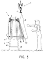
- the device according to the invention is used in combination with an overhead conveyor C, FIG. 3, which transports parts such as half-carcasses of pork to be cut, according to a determined spacing and speed.
- the device 1 is placed under the conveyor C, and offset as appropriate on one side. Its function is to constitute a support plane for the half-carcasses transported by the conveyor C along the length of a sawing station, downstream of which the half-carcasses are then lowered onto a horizontal conveyor, not shown here, where the actual cutting takes place with a knife, as explained above.
- the support plane of the device 1 is produced by a set of pallets 2 which are follow, articulated around their upper end to an endless loop consisting of a chain 3 forming a straight line strand 30 which will be placed parallel to the conveyor C, and scroll in the same direction and at the same speed as the latter.
- the pallets 2 which arrive substantially vertical at the upstream end of the strand 30 will gradually rise by pivoting along a first section 30a, FIG. 1, thus engaging in the passage of the half-carcasses D, FIG. 3. Consequently, each half-carcass D arriving at the level of the device 1 will first meet the base of pallets 2 which will therefore accompany it in its movement.
- the pallets which rise along the section 30a will push towards the opposite side the half-carcass D, by making it tilt transversely around its suspension hook S until it is in support on them as shown in Fig. 3.
- This support is maintained along an intermediate section 30b of the strand 30, the length of which corresponds to the sawing station.
- the pallets gradually release the half-carcass D which continues its progression until a lowering station, not shown.
- the pallets 2 are elongated rectangular blades, advantageously made of a food-grade synthetic material such as polyethylene. On the section 30b of the strand going along the sawing station, they follow each other in an almost contiguous manner, so as to form a work plan without significant discontinuities.
- the endless chain 3 is carried on top of a frame 4 in the general form of a gantry, the elements of which are preferably made of stainless steel.
- the frame 4 comprises two pairs of ends and a middle pair of inclined legs 40 joined by transverse and longitudinal elements, carrying a spar 42, which in turn carries, by means of uprights 43 and crosspieces 44 a rectangular upper frame 5 arranged horizontally.
- two cogwheels 6, 7 are mounted horizontally, one of which is driving, on which the endless chain 3 is engaged and kept in tension by conventional means.
- the chain 3 which includes rollers 32, is retained and guided in two rectilinear strands, the forward strand 30 and a return strand 31, in paths suspended under the two lateral side members of the frame 5 , respectively 51 and 52, Fig. 4.
- Each of these paths is formed by two identical parallel tubular rails of rectangular section, that is an inner rail 8 and an outer rail 9 arranged at the same level and spaced apart by a distance corresponding to the diameter of the rollers 32 of the chain 3.
- the rails 8 and 9 are fixed under each spar 51 and 52 by means of stirrups 10.
- the chain 3 is retained inside the rails 8 and 9 and, for this purpose, it is provided with upper sliding pads 37 and lower 38 arranged in pairs.
- the upper shoe 37 and the lower shoe 38 are respectively placed externally with respect to the upper link 33 and to the lower link 34 of the same link in the vertical direction, and parallel to these.
- the pads 37, 38 are for example fixed to their respective mesh at two points such as 36 spaced apart on the longitudinal axis of the latter.
- the pairs of pads 37, 38 are repeated at the rate of one every two links.
- the pads 37, 38 come to cover the two rails 8, 9 above and below, projecting from the chain 3. Their spacing being only very slightly less than the height of the rails 8, 9, in addition to retaining the chain at the 'inside these, they ensure its transverse maintenance in a substantially horizontal position.
- the pads 37, 38 are advantageously made of a synthetic material such as polyamide, retained for its sliding qualities on metal surfaces.
- the pallets 2 which have a width very slightly less than the pitch of the chain 3 are each connected to a link by an articulation 11.
- the articulation 11 comprises a plate 12 mounted integral with the lower mesh 34 of the link, and which extends outwardly beyond the outer rail 9.
- the plate 12 is placed under the lower shoe 38, FIG. 4, mounted with it under the mesh 34 by means of the fasteners 36.
- the plate 12 can be mounted directly under the mesh 34.
- a step shown in 120 at the Fig. 5.
- the plate 12 Under its outer edge, the plate 12 carries an axis 13 parallel to the longitudinal axis of the link.
- the pallet 2 is pivotally mounted around this axis by means of a yoke 14 fixed at its upper end.
- the pallets 2 are controlled in inclination along the outward strand 30.
- the pallets 2 rise first progressively on a first section 30a, are maintained in a determined inclination along an intermediate section 30b, then gradually decrease on a last section 30c.
- the intermediate section 30b is itself subdivided into two parts between which the inclination of the pallets will vary gradually, along a transition section.
- the means shown for controlling the pallets 2 in inclination is a continuous guide along the outward strand 30, forming a sliding ramp on which their lower part is supported. It is advantageously a round bar 15, FIG. 3, the plan form of which is shown in broken lines in FIG. 2.
- the guide 15 can be extended all around the device, to prevent the pallets 2 from pivoting inward.
- the pallets 2 can undergo cleaning along the return strand 31, cleaning which may include brushing, for example by means of rotary brushes oriented vertically, washing with spraying of an agent detergent, and a rinse. It will be noted that when they pass around the toothed wheels 6, 7, the pallets 2 are in a suitable situation for cleaning their adjacent edges, due to the fact that they separate from one another.
- protective covers 16 can be provided, Figs. 1 and 2, wrapping the ends of the device.
Landscapes
- Life Sciences & Earth Sciences (AREA)
- Engineering & Computer Science (AREA)
- Food Science & Technology (AREA)
- Chain Conveyers (AREA)
Applications Claiming Priority (2)
| Application Number | Priority Date | Filing Date | Title |
|---|---|---|---|
| FR9402305A FR2716340B1 (fr) | 1994-02-23 | 1994-02-23 | Dispositif pour poste de sciage dans une chaîne de découpage primaire d'animaux de boucherie. |
| FR9402305 | 1994-02-23 |
Publications (1)
| Publication Number | Publication Date |
|---|---|
| EP0668018A1 true EP0668018A1 (de) | 1995-08-23 |
Family
ID=9460522
Family Applications (1)
| Application Number | Title | Priority Date | Filing Date |
|---|---|---|---|
| EP95460008A Withdrawn EP0668018A1 (de) | 1994-02-23 | 1995-02-20 | Vorrichtung für Säge-Stelle in einer primären Schneidanlage von Schlachttieren |
Country Status (2)
| Country | Link |
|---|---|
| EP (1) | EP0668018A1 (de) |
| FR (1) | FR2716340B1 (de) |
Cited By (6)
| Publication number | Priority date | Publication date | Assignee | Title |
|---|---|---|---|---|
| EP1008301A1 (de) * | 1998-12-10 | 2000-06-14 | Inalca- Industria Alimentare Carni- Societa' per Azioni | Linie zum Abstreifen des Fleisches von Rindervierteln |
| DE102004060401A1 (de) * | 2004-12-14 | 2006-06-29 | Banss Schlacht- und Fördertechnik GmbH | Verfahren sowie Anordnung zum Bearbeiten von Schlachttierkörperhälften |
| FR2940747A1 (fr) * | 2009-01-06 | 2010-07-09 | Couedic Madore Equipement | Procede de decoupe d'une demi-carcasse de porc |
| EP3537882A4 (de) * | 2016-11-09 | 2020-04-29 | Scott Automation & Robotics Pty Limited | Kadaververarbeitungssystem und -verfahren |
| CN113678869A (zh) * | 2021-08-31 | 2021-11-23 | 无为市康宁科技食品有限公司 | 一种宰后生猪分割系统 |
| CN115605090A (zh) * | 2020-05-15 | 2023-01-13 | 北欧机械制造鲁道夫巴德尔有限及两合公司(De) | 用于运输去除内脏的家禽屠体或其部分的运输设备以及用于附接和加工家禽屠体或其部分的设备和方法 |
Citations (11)
| Publication number | Priority date | Publication date | Assignee | Title |
|---|---|---|---|---|
| US3027991A (en) * | 1958-11-03 | 1962-04-03 | Leslie L Flaherty | Hog handling device |
| FR2121645A1 (de) * | 1971-01-07 | 1972-08-25 | Stork Amsterdam | |
| CA968512A (en) * | 1973-03-12 | 1975-06-03 | Knud Simonsen Industries Limited | Carcass support |
| US4158903A (en) * | 1974-06-10 | 1979-06-26 | Edward Ochylski | Hog head removal method |
| DE3011026A1 (de) * | 1980-03-21 | 1981-10-01 | Herta Kg Karl Schweisfurth, 4352 Herten | Verfahren und anlage zum zerlegen von auf einem haengefoerdermittel zu einem ausloeseplatz gefoerderten schlachttierkoerpern, insbesondere rindervierteln |
| US4651384A (en) * | 1983-02-18 | 1987-03-24 | Korhonen K J | Support apparatus for butchering an animal quarter |
| EP0235001A1 (de) * | 1986-02-12 | 1987-09-02 | SOCIETE DES VIANDES DU COTENTIN, Société dite: | Einrichtung zum hängenden Zerlegen von Rindervordervierteln |
| FR2598887A1 (fr) * | 1986-05-22 | 1987-11-27 | Conseil Organisation Formation | Procede et installation de desossage d'un quartier arriere de boucherie. |
| EP0300940A1 (de) * | 1987-06-18 | 1989-01-25 | S.O.C.O.F. Societe De Conseil En Organisation Et De Formation | Verfahren und Vorrichtung zum Ausbeinen von einem Schlacht-Hinterteil |
| EP0443101A2 (de) * | 1989-11-13 | 1991-08-28 | Banss Maschinenfabrik GmbH & Co. KG | Anlage zum erleichterten Zerlegen von Schlachttierteilen, insbesondere Rindervierteln |
| EP0487075A1 (de) * | 1990-11-22 | 1992-05-27 | Riniker AG | Schlachtanlage |
-
1994
- 1994-02-23 FR FR9402305A patent/FR2716340B1/fr not_active Expired - Fee Related
-
1995
- 1995-02-20 EP EP95460008A patent/EP0668018A1/de not_active Withdrawn
Patent Citations (11)
| Publication number | Priority date | Publication date | Assignee | Title |
|---|---|---|---|---|
| US3027991A (en) * | 1958-11-03 | 1962-04-03 | Leslie L Flaherty | Hog handling device |
| FR2121645A1 (de) * | 1971-01-07 | 1972-08-25 | Stork Amsterdam | |
| CA968512A (en) * | 1973-03-12 | 1975-06-03 | Knud Simonsen Industries Limited | Carcass support |
| US4158903A (en) * | 1974-06-10 | 1979-06-26 | Edward Ochylski | Hog head removal method |
| DE3011026A1 (de) * | 1980-03-21 | 1981-10-01 | Herta Kg Karl Schweisfurth, 4352 Herten | Verfahren und anlage zum zerlegen von auf einem haengefoerdermittel zu einem ausloeseplatz gefoerderten schlachttierkoerpern, insbesondere rindervierteln |
| US4651384A (en) * | 1983-02-18 | 1987-03-24 | Korhonen K J | Support apparatus for butchering an animal quarter |
| EP0235001A1 (de) * | 1986-02-12 | 1987-09-02 | SOCIETE DES VIANDES DU COTENTIN, Société dite: | Einrichtung zum hängenden Zerlegen von Rindervordervierteln |
| FR2598887A1 (fr) * | 1986-05-22 | 1987-11-27 | Conseil Organisation Formation | Procede et installation de desossage d'un quartier arriere de boucherie. |
| EP0300940A1 (de) * | 1987-06-18 | 1989-01-25 | S.O.C.O.F. Societe De Conseil En Organisation Et De Formation | Verfahren und Vorrichtung zum Ausbeinen von einem Schlacht-Hinterteil |
| EP0443101A2 (de) * | 1989-11-13 | 1991-08-28 | Banss Maschinenfabrik GmbH & Co. KG | Anlage zum erleichterten Zerlegen von Schlachttierteilen, insbesondere Rindervierteln |
| EP0487075A1 (de) * | 1990-11-22 | 1992-05-27 | Riniker AG | Schlachtanlage |
Cited By (9)
| Publication number | Priority date | Publication date | Assignee | Title |
|---|---|---|---|---|
| EP1008301A1 (de) * | 1998-12-10 | 2000-06-14 | Inalca- Industria Alimentare Carni- Societa' per Azioni | Linie zum Abstreifen des Fleisches von Rindervierteln |
| US6334811B1 (en) | 1998-12-10 | 2002-01-01 | Inalca-Industria Alimentare-Carni-Societa' Per Azioni | Line for stripping meat from cattle fore and hind quarters |
| DE102004060401A1 (de) * | 2004-12-14 | 2006-06-29 | Banss Schlacht- und Fördertechnik GmbH | Verfahren sowie Anordnung zum Bearbeiten von Schlachttierkörperhälften |
| FR2940747A1 (fr) * | 2009-01-06 | 2010-07-09 | Couedic Madore Equipement | Procede de decoupe d'une demi-carcasse de porc |
| EP3537882A4 (de) * | 2016-11-09 | 2020-04-29 | Scott Automation & Robotics Pty Limited | Kadaververarbeitungssystem und -verfahren |
| CN115605090A (zh) * | 2020-05-15 | 2023-01-13 | 北欧机械制造鲁道夫巴德尔有限及两合公司(De) | 用于运输去除内脏的家禽屠体或其部分的运输设备以及用于附接和加工家禽屠体或其部分的设备和方法 |
| US11751579B2 (en) | 2020-05-15 | 2023-09-12 | Nordischer Maschinenbau Rud. Baader Gmbh + Co. Kg | Transport apparatus for transporting eviscerated poultry carcasses or parts thereof, and apparatus and method for attaching and processing the poultry carcasses or parts thereof |
| CN115605090B (zh) * | 2020-05-15 | 2023-10-27 | 北欧机械制造鲁道夫巴德尔有限及两合公司 | 用于运输去除内脏的家禽屠体或其部分的运输设备以及用于附接和加工家禽屠体或其部分的设备和方法 |
| CN113678869A (zh) * | 2021-08-31 | 2021-11-23 | 无为市康宁科技食品有限公司 | 一种宰后生猪分割系统 |
Also Published As
| Publication number | Publication date |
|---|---|
| FR2716340A1 (fr) | 1995-08-25 |
| FR2716340B1 (fr) | 1996-06-07 |
Similar Documents
| Publication | Publication Date | Title |
|---|---|---|
| EP0014298B1 (de) | Umlaufende Fördereinrichtung mit örtlich unterschiedlichen Geschwindigkeiten und Anwendung für Rollsteige | |
| EP0193476A1 (de) | Maschine zum Behandeln von Porree | |
| EP0668018A1 (de) | Vorrichtung für Säge-Stelle in einer primären Schneidanlage von Schlachttieren | |
| CA2968911A1 (fr) | Chariot de transport d'un convoyeur a bande, installation mobile de convoyage comprenant un tel chariot, et procede de deplacement associe | |
| EP0300940B1 (de) | Verfahren und Vorrichtung zum Ausbeinen von einem Schlacht-Hinterteil | |
| FR2679869A1 (fr) | Machine destinee a l'emballage d'articles de dimensions universelles au moyen de morceaux d'une bande de matiere thermoretractable. | |
| FR2976195A1 (fr) | Dispositif de convoyage d'objets tels que des fruits ou legumes a zones amont d'individualisation bilaterale. | |
| EP2462810A1 (de) | Messergehäuse für eine Maschine zum Zerteilen von Schlachttierkörpern | |
| BE1003931A3 (fr) | Dispositif de securite pour les machines a depouiller la viande. | |
| FR2598887A1 (fr) | Procede et installation de desossage d'un quartier arriere de boucherie. | |
| EP0135417A1 (de) | Vorrichtung zum Schneiden länglicher Elemente mit rechteckigem Querschnitt in Stücke einer vorbestimmten Länge | |
| FR2627059A1 (fr) | Procede et installation pour detacher la depouille ou la peau de carcasses d'animaux | |
| FR2524355A1 (fr) | Appareil pour enlever les bavures sur un produit de coulee continue | |
| EP2550866B1 (de) | Fließband mit Zapfen für Vorrichtung zur Geflügelzerteilung | |
| CA2277693A1 (fr) | Machine pour retirer le gras de la longe d'une demi-carcasse | |
| EP1923335A1 (de) | Anlage zur Beförderung einer Ladung auf parallelen Laufbändern | |
| FR2512642A1 (fr) | Machine automatique pour le nettoyage des jambons crus apres salage et avant massage | |
| EP0598957B1 (de) | Vorrichtung zum Enthäuten von Schlachttieren, insbesondere von Schafen und Ziegen | |
| FR2693441A1 (fr) | Dispositif transporteur comportant un tapis convoyeur sans fin. | |
| EP0108009A1 (de) | Automatische Maschine zum Abgraten von Werkstücken kleiner Ausmassen | |
| FR2678238A1 (fr) | Machine pour la pose de poignees sur des colis. | |
| FR2625076A1 (fr) | Dispositif pour refendre des corps d'animaux abattus, comprenant un chariot mobile portant une scie ou analogue se deplacant verticalement | |
| FR2515151A1 (fr) | Tete motrice d'un convoyeur de mine et convoyeur comprenant cette tete | |
| FR2661862A1 (fr) | Procede et machine pour decouper en lamelles dans la meme orientation des produits varies, tels que des champignons. | |
| FR2648118A1 (fr) | Convoyeur de plateaux notamment pour l'industrie agro-alimentaire |
Legal Events
| Date | Code | Title | Description |
|---|---|---|---|
| PUAI | Public reference made under article 153(3) epc to a published international application that has entered the european phase |
Free format text: ORIGINAL CODE: 0009012 |
|
| AK | Designated contracting states |
Kind code of ref document: A1 Designated state(s): BE CH DE ES FR GB LI LU NL |
|
| STAA | Information on the status of an ep patent application or granted ep patent |
Free format text: STATUS: THE APPLICATION IS DEEMED TO BE WITHDRAWN |
|
| 18D | Application deemed to be withdrawn |
Effective date: 19960224 |