EP0664581A2 - Niederprofilverbinder zwischen Leiterplatten - Google Patents
Niederprofilverbinder zwischen Leiterplatten Download PDFInfo
- Publication number
- EP0664581A2 EP0664581A2 EP94309377A EP94309377A EP0664581A2 EP 0664581 A2 EP0664581 A2 EP 0664581A2 EP 94309377 A EP94309377 A EP 94309377A EP 94309377 A EP94309377 A EP 94309377A EP 0664581 A2 EP0664581 A2 EP 0664581A2
- Authority
- EP
- European Patent Office
- Prior art keywords
- contact
- housing
- contacts
- connector
- electrical
- Prior art date
- Legal status (The legal status is an assumption and is not a legal conclusion. Google has not performed a legal analysis and makes no representation as to the accuracy of the status listed.)
- Granted
Links
Images


Classifications
-
- H—ELECTRICITY
- H01—ELECTRIC ELEMENTS
- H01R—ELECTRICALLY-CONDUCTIVE CONNECTIONS; STRUCTURAL ASSOCIATIONS OF A PLURALITY OF MUTUALLY-INSULATED ELECTRICAL CONNECTING ELEMENTS; COUPLING DEVICES; CURRENT COLLECTORS
- H01R12/00—Structural associations of a plurality of mutually-insulated electrical connecting elements, specially adapted for printed circuits, e.g. printed circuit boards [PCB], flat or ribbon cables, or like generally planar structures, e.g. terminal strips, terminal blocks; Coupling devices specially adapted for printed circuits, flat or ribbon cables, or like generally planar structures; Terminals specially adapted for contact with, or insertion into, printed circuits, flat or ribbon cables, or like generally planar structures
- H01R12/70—Coupling devices
- H01R12/71—Coupling devices for rigid printing circuits or like structures
- H01R12/712—Coupling devices for rigid printing circuits or like structures co-operating with the surface of the printed circuit or with a coupling device exclusively provided on the surface of the printed circuit
- H01R12/716—Coupling device provided on the PCB
-
- H—ELECTRICITY
- H01—ELECTRIC ELEMENTS
- H01R—ELECTRICALLY-CONDUCTIVE CONNECTIONS; STRUCTURAL ASSOCIATIONS OF A PLURALITY OF MUTUALLY-INSULATED ELECTRICAL CONNECTING ELEMENTS; COUPLING DEVICES; CURRENT COLLECTORS
- H01R12/00—Structural associations of a plurality of mutually-insulated electrical connecting elements, specially adapted for printed circuits, e.g. printed circuit boards [PCB], flat or ribbon cables, or like generally planar structures, e.g. terminal strips, terminal blocks; Coupling devices specially adapted for printed circuits, flat or ribbon cables, or like generally planar structures; Terminals specially adapted for contact with, or insertion into, printed circuits, flat or ribbon cables, or like generally planar structures
- H01R12/50—Fixed connections
- H01R12/51—Fixed connections for rigid printed circuits or like structures
- H01R12/55—Fixed connections for rigid printed circuits or like structures characterised by the terminals
- H01R12/58—Fixed connections for rigid printed circuits or like structures characterised by the terminals terminals for insertion into holes
-
- H—ELECTRICITY
- H01—ELECTRIC ELEMENTS
- H01R—ELECTRICALLY-CONDUCTIVE CONNECTIONS; STRUCTURAL ASSOCIATIONS OF A PLURALITY OF MUTUALLY-INSULATED ELECTRICAL CONNECTING ELEMENTS; COUPLING DEVICES; CURRENT COLLECTORS
- H01R4/00—Electrically-conductive connections between two or more conductive members in direct contact, i.e. touching one another; Means for effecting or maintaining such contact; Electrically-conductive connections having two or more spaced connecting locations for conductors and using contact members penetrating insulation
- H01R4/02—Soldered or welded connections
- H01R4/028—Soldered or welded connections comprising means for preventing flowing or wicking of solder or flux in parts not desired
Definitions
- This invention relates to electrical connectors and more particularly to board to board electrical connectors for interconnecting circuits between parallel circuit boards.
- U.S. Patent No. 5,199,884 discloses a blind matable miniature connector for interconnecting circuits between parallel circuit boards.
- the connector in this patent includes contacts placed on close center lines such as on the order 0.5 mm (0.020 inches) for high density interconnection. Spring design of the contacts, and the housings require a minimum height of about 5 mm (0.20 inches), which means that the boards to be connected can be no closer than 5 mm (0.20 inches) apart.
- connectors that will allow circuit boards to be placed at lower stack heights on the order of 3.0 mm and 4.0 mm (0.118 inches to 0.157 inches) . It is further desirable that the low profile connector contacts also provide for high density interconnections.
- the present invention is directed an electrical connector assembly comprising first and second connectors having respective first and second housings and respective first and second electrical contacts secured in at least one row in the associated housing.
- the first and second contacts include respective first and second contact sections electrically engagable along a mating interface of the first and second connectors.
- Each first contact section is joined to an axially extending intermediate section proximate an inner wall of the first housing and is laterally deflectable upon mating.
- Each second contact section is a post portion extending axially along an outer wall of the second housing and engagable with the first contact section.
- the first contact section is a transverse arm extending outwardly from the intermediate section and includes a contact surface.
- the post portion of the second contact is spaced inwardly from an outer wall of the second housing and includes a contact surface, whereby upon mating of the first and second connectors the contact surfaces of the first contacts and second contacts slidably engage each other deflecting the arms in a lateral direction parallel to the outer wall of the second housing.
- the post portions extend along and past the arms and are in spring-biased engagement therewith.
- the present invention is a low profile board to board connector assembly including a plug and receptacle, each having respective housings and arrays of contacts of thin metal set on edge in the housing on center lines complimentary to the center lines of the circuits on the printed circuit boards.
- the contacts include edge contact surfaces projecting from the housings in a common plane for soldering to the board circuits.
- the receptacle housing includes a floor, opposed side walls, and opposed end walls, together defining an interior cavity configured to receive the plug housing inserted therein.
- the housing floor has a plurality of contact receiving slots extending therethrough, each slot having a receptacle contact disposed therein.
- the receptacle contacts have a body with a C-shaped configuration and include a base, an intermediate portion and an arm, the base and arm extending essentially parallel to one another from the intermediate portion.
- the outward edge of the base defines the edge contact surface for engagement with a respective circuit on a circuit board and the intermediate portion and arm define a spring, the arm including a contact surface adapted to mate with a corresponding plug contact upon mating the receptacle and plug.
- the receptacle contact is disposed in the slot of the housing floor such that the board contact surface thereof is spaced outwardly from the outer major surface of the floor and the intermediate portion and arm extend into the interior cavity of the receptacle housing, the arm extending transversely of the axis of mating in a first direction.
- the arm is adapted to be deflected transversely of the axis of mating in a second direction by the corresponding plug contact when the receptacle and plug are mated.
- the plug housing includes a floor having a plurality of cavity walls extending laterally across the interior surface of the floor and a plurality of contact receiving apertures extending through the floor.
- Each plug contact has an L-shaped configuration including a base and a transversely directed post extending from an interior edge of the base.
- the outer edge of the base defines an edge contact surface for engagement with a respective circuit of a circuit board and the post defines a mating surface for a corresponding one of the receptacle contacts.
- the plug contact is disposed in the plug housing such that the base portion extends along the outer surface of the floor and the post portion extends through the aperture into a contact receiving cavity adjacent a respective cavity wall.
- the post of the plug contact engages the contact surface of the spring arm of the receptacle contact in a sliding engagement, deflecting the spring arm in a direction transverse to the axis of mating.
- the post co-extends past the spring arm and is in spring bias engagement therewith resulting in a low profile connector thus minimizing board to board spacing.
- the present invention is also directed to electrical contacts having means for preventing solder from being wicked into a connector housing.
- Each contact includes a body having opposed side surfaces and first and second portions, the first portion defines a base having a contact surface extending along an outer edge thereof for electrical connection to a circuit of a circuit board.
- the second portion is securable within a housing and includes a contact section for mating with a complementary contact of a mating connector.
- At least one side surface of the base includes at least one interruption extending at least between the edge contact surface thereof and the second body portion.
- the interruption prevents solder from being wicked into the connector housing.
- One or more interruptions can be located on the side body surfaces.
- the receptacle and plug contacts further include a plurality of grooves on at least one side thereof to prevent solder from being wicked up into the mating area when the connector is soldered to the circuit board.
- the present invention also provides a means for adjusting the stacking height between parallel boards by providing another embodiment of the plug contact wherein the width of the base of the L-shaped member is selected to provide a desired stacking height.
- connector assembly 20 includes a receptacle 22 having a plurality of receptacle contacts 44 disposed therein and a plug 70 having a plurality of contacts 92 disposed therein.
- Receptacle 22 includes a housing 24 having a floor 26 having major inner and outer surfaces 28,30 respectively.
- Floor 26 further includes a plurality of contact receiving slots 32 extending therethrough between the inner and outer major surfaces 28,30.
- Receptacle housing 24 also includes opposed side walls 34 and opposed end walls 38, the floor 26, side walls 34 and end walls 38 together defining a cavity 42 configured to receive a portion of the plug 70 therein upon mating the receptacle 22 and plug 70.
- End walls 38 include apertures 40 for receiving guide pins 78 of the plug housing 72 when the receptacle 22 and plug 70 are mated.
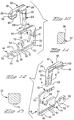
- Plug 70 as shown in Figures 1 through 4 includes a plug housing 72 having a floor 74 and opposed major surfaces 76 and 80 and a plurality of contact receiving apertures 84 extending through the floor 74.
- the inner surface 76 of floor 74 includes posts 78, which extend forwardly therefrom for engagement with corresponding apertures 40 in the receptacle housing 24 when the plug 70 is mated to receptacle 22.
- the outer surface 80 of floor 74 includes posts 82 for mounting plug 70 onto a circuit board 116 as can best be seen in Figures 4 through 6.
- the major inner surface 76 of floor 74 further includes a center wall 86 extending longitudinally therealong.
- a plurality of side walls 88 extend essentially perpendicular to the center wall 86 and between the respective apertures 84 and define internal open ended cavities 90 for receiving the mating portions of the respective receptacle and plug contacts 44,92 as more fully described below.
- Receptacle and plug housings 24,72 respectively are preferably made from a high temperature resistant material such as a liquid crystal polymer or the like. The material selected must be able to withstand temperatures of about 250° C that are typically achieved during a soldering process, such as infrared reflow soldering or other methods as known in the art.
- Receptacle contacts 44 as best seen in Figures 10 and 12 have C-shaped bodies 46 having opposed major surfaces 45 and 47.
- Body 46 includes a base 48, intermediate portion 60 and an arm 62.
- Base 48 has an outer contact surface 50 for engaging corresponding circuit pads 114 on circuit board 112 as shown in Figures 4 through 7, and 16.
- Base 48 includes a plurality of dimples or protrusions 52,53 extending outwardly from major surface 45, which aid in positioning receptacle contact 44 within the corresponding slot 32.
- the receptacle contact 44 is made from metal stock material having a thickness of approximately 0.15 mm (0.006 inches).
- the metal selected preferably has a high yield strength in the range of 105-125 thousand p.s.i. to assure that sufficient normal force is achieved in the mated assembly.
- the protrusions 52,53 aid in the absorbing the clearance within the slot 32 so that the other major surface 47 of the contact 44 is held flat against a wall within the slot 32.
- the position of protrusion 53 in particular, also influences the spring characteristics of spring arm 66 and determines the amount of stress transmitted to base 48.
- Base 48 further includes a retention means 54 which engages the surface of receptacle housing 24 when contact 44 is disposed within the slot 32. Also seen in Figure 4, when contact 44 is disposed within its respective slot 32, arm 62 and a portion of the intermediate portion 60 extend into the receptacle cavity 42.
- the base 48 of contact 44 further includes a short leg portion 56 having a groove 55 therein for receiving the side wall 34 therein. As shown in Figures 4, 10, 12 and 16 the base 48 further includes two grooves 58 on each side thereof that act to prevent the solder 59 from being wicked into the receptacle cavity, as shown in Figure 16.
- the outer edge 50 of contact 44 has an indentation 51 that allows a fillet of solder to spread beneath the thin edge of the contact 44 as seen in Figure 16.
- the intermediate portion 60 includes an inner tapered edge 61. This tapering evenly distributes stresses along the length of portion 60 and arm 62, thus optimizing the spring characteristics of receptacle contact 44.
- the arm 62 is shorter than the base 48 and includes a radiused portion 66 at the leading end 64 thereof as shown in Figure 11.
- the radiused surface 66 provides a ramp and a contact surface 68 for engaging a corresponding contact surface 110 of the plug contact 92 when the receptacle 22 and plug 70 are mated, as is more fully described below.
- the receptacle 22 is assembled by inserting C-shaped contact members 44 into the respective slots 32 of floor 26 from the outer surface 30 thereof such that the arm 62 extends into the cavity 42.
- the lower portion of base 48 extends from the outer surface 30 of housing 24 with the slot 55 capturing the respective housing side wall 34, and the retention means 54 engages an inner wall surface.
- the protrusions 52,53 as can best be seen in Figure 5, hold contact 44 against one of the walls of the slot 32.
- the solder wicking prevention grooves 58 lie approximate the outer surface 30 of floor 26.
- Figure 4 also shows the receptacle 22 having its terminals 44 and outer edge contact surface 50 positioned on corresponding circuit pads 114 of circuit board 112. Contact 44 is shown soldered to the pad in Figure 16, which also illustrates the function of grooves 58.
- plug contacts 92 have an L-shaped configuration including a base 94 having an inner and outer surface 93,95 respectively and a transversely directed post 104 extending from an interior end thereof.
- the base 94 further includes a thinner area 96 which defines a thin outer edge contact surface 98 for engagement with a respective circuit 118 on a circuit board 116 as shown in Figures 4 through 7.
- Contact 92 is preferably made from metal stock such as phosphor bronze of the like having a thickness of approximately 0.32 mm (0.0126 inches), which preferably has reduced thickness of approximately 0.23 mm at 96 to provide the contact edge surface 98.
- the plug contact 92 further includes solder wicking prevention grooves 102 on one side thereof.
- Post 104 includes a retention area 106 for holding the contact 92 within the housing floor 74 and has a radiused and tapered section 108 at the leading end thereof leading to the contact surface 110, as seen more clearly in Figures 10, 12 and 13.
- the L-shaped plug contact 92 is assembled into the plug housing 72 by inserting the post 104 into respective apertures 84 from the outer surface 80 of floor 74 such that the base 94 of the contact lies against the outer surface 80 of housing 72 and the straight side of post 104 extends adjacent one of the side walls 88 and into cavities 90, as can be seen in Figures 4 and 5.
- the respective contacts 92 are secured in the plug housing by means of the retention feature 106 and essentially in an interference fit.
- the lead-in surface 108 of post 104 of the plug contact 92 engages the corresponding contact surface 68 of the spring arm 62 of the receptacle contact 44 in sliding engagement therewith.
- the surface 108 deflects the spring arm 62 in a direction transversely to the axis of mating.
- the intermediate body portions 60 of the receptacle contact 44 twists thereby providing sufficient normal force between the two contact members.
- the amount of normal force can be controlled by adjusting the position of slot 32 with respect to apertures 84 thereby determining the amount of deflection of spring arm 62.
- the post 104 co-extends past the spring arm 62 and is in spring bias engagement therewith.
- the resulting assembly 20 has a low profile thus minimizing the board to board spacing as can be seen in Figures 6 and 7.
- the configuration of the contacts 44, 92 and housings 22, 72 and the high deflection force of the contacts 44 provide a low profile connector assembly that will permit mating of the contacts 44, 92 even when the contacts 44,92 of each matable pair are slightly misaligned with respect to each other, thereby permitting multiple arrays of rigidly mounted contacts 44, 92 in multiple connectors 10 to be mated simultaneously, thus defining an arrangement that compensates for tolerances.
- the protrusions 52,53 are on only one side of the contact 44.
- all the contacts 44 in the first row are thrown in a common first direction in their respective slots 32 and all the contacts 44 in the second row are thrown in a common second direction, opposed to the first direction.
- the shape of plug base 94 throws the plug contact 92 to one side of its respective aperture 84 as shown in Figures 1, 3 and 7.
- the plug contacts 92 in the first row are thrown in a common direction opposite to that of the receptacle contacts 44 thereby enabling the corresponding contact surfaces 66, 110 to engage each other.
- the plug contacts 92 in the second row are thrown in a common direction opposite to that of the receptacle contacts 44 thereby enabling the corresponding contact surfaces 66, 110 to engage each other in the second row.
- Figures 8, 9, 14 and 15 illustrate the present invention using another embodiment 192 of the plug contact in which the contact base 194 is wider thereby providing a greater stack height between the parallel circuit boards when the connector 120 is assembled.
- the base 194 of the L-shaped base of contact 192 includes the thinned area 196 and the corresponding grooves 202 to prevent solder wicking in the same manner as previously described.
- the floor portion 194 may further include an aperture 197 as can be seen in the above Figures.
- Figure 8 illustrates connector assembly 120 prior to mating and Figures 9 illustrates the assembly 120 after mating.
Applications Claiming Priority (2)
| Application Number | Priority Date | Filing Date | Title |
|---|---|---|---|
| US184522 | 1994-01-21 | ||
| US08/184,522 US5395250A (en) | 1994-01-21 | 1994-01-21 | Low profile board to board connector |
Publications (3)
| Publication Number | Publication Date |
|---|---|
| EP0664581A2 true EP0664581A2 (de) | 1995-07-26 |
| EP0664581A3 EP0664581A3 (de) | 1996-10-30 |
| EP0664581B1 EP0664581B1 (de) | 1999-07-21 |
Family
ID=22677248
Family Applications (1)
| Application Number | Title | Priority Date | Filing Date |
|---|---|---|---|
| EP94309377A Expired - Lifetime EP0664581B1 (de) | 1994-01-21 | 1994-12-15 | Niederprofilverbinder zwischen Leiterplatten |
Country Status (7)
| Country | Link |
|---|---|
| US (1) | US5395250A (de) |
| EP (1) | EP0664581B1 (de) |
| JP (1) | JPH07220830A (de) |
| KR (1) | KR950034923A (de) |
| CN (1) | CN1040053C (de) |
| DE (1) | DE69419590T2 (de) |
| TW (1) | TW239915B (de) |
Cited By (2)
| Publication number | Priority date | Publication date | Assignee | Title |
|---|---|---|---|---|
| WO2005022699A2 (en) * | 2003-08-27 | 2005-03-10 | Molex Incorporated | Board-to-board electrical connector assembly |
| GB2413017A (en) * | 2004-04-06 | 2005-10-12 | Ford Global Tech Llc | An electrical connector for a vehicle |
Families Citing this family (73)
| Publication number | Priority date | Publication date | Assignee | Title |
|---|---|---|---|---|
| US5403206A (en) * | 1993-04-05 | 1995-04-04 | Teradyne, Inc. | Shielded electrical connector |
| NL9301779A (nl) * | 1993-10-14 | 1995-05-01 | Connector Systems Tech Nv | Elektrische connector voor montage op het oppervlak van een printplaat. |
| KR100339767B1 (ko) * | 1993-12-09 | 2002-11-30 | 메소드 일렉트로닉스 인코포레이티드 | 전기신호전달용전기커넥터및그제조방법 |
| US5567166A (en) * | 1994-04-08 | 1996-10-22 | Berg Technology, Inc. | Low profile connector and processes for making and using the same |
| US6939173B1 (en) | 1995-06-12 | 2005-09-06 | Fci Americas Technology, Inc. | Low cross talk and impedance controlled electrical connector with solder masses |
| US5545051A (en) * | 1995-06-28 | 1996-08-13 | The Whitaker Corporation | Board to board matable assembly |
| US5876217A (en) * | 1996-03-14 | 1999-03-02 | Molex Incorporated | Electric connector assembly with improved retention characteristics |
| US5885092A (en) * | 1996-06-21 | 1999-03-23 | Molex Incorporated | Electric connector assembly with improved registration characteristics |
| US6093035A (en) * | 1996-06-28 | 2000-07-25 | Berg Technology, Inc. | Contact for use in an electrical connector |
| AT1695U1 (de) * | 1996-07-29 | 1997-09-25 | Mikroelektronik Ges Mit Beschr | Schaltanordnung |
| TW298347U (en) * | 1996-08-08 | 1997-02-11 | Hon Hai Prec Ind Co Ltd | Improved structure of connector terminal |
| US6042389A (en) * | 1996-10-10 | 2000-03-28 | Berg Technology, Inc. | Low profile connector |
| US6241535B1 (en) | 1996-10-10 | 2001-06-05 | Berg Technology, Inc. | Low profile connector |
| SG71046A1 (en) | 1996-10-10 | 2000-03-21 | Connector Systems Tech Nv | High density connector and method of manufacture |
| US6139336A (en) * | 1996-11-14 | 2000-10-31 | Berg Technology, Inc. | High density connector having a ball type of contact surface |
| JP3350843B2 (ja) * | 1996-12-20 | 2002-11-25 | モレックス インコーポレーテッド | インサートモールドで電気コネクタを製造する方法 |
| US5931689A (en) * | 1997-08-06 | 1999-08-03 | Molex Incorporated | Electric connector assembly with improved locking characteristics |
| TW364676U (en) * | 1997-11-22 | 1999-07-11 | Hon Hai Prec Ind Co Ltd | Outlet connector module |
| US6431889B1 (en) | 1997-12-23 | 2002-08-13 | Berg Technology, Inc. | High density edge card connector |
| CN1087106C (zh) * | 1998-02-27 | 2002-07-03 | 鸿海精密工业股份有限公司 | 板对板电连接器 |
| US6439931B1 (en) | 1998-05-13 | 2002-08-27 | Molex Incorporated | Method and structure for tuning the impedance of electrical terminals |
| US6171156B1 (en) * | 1999-04-20 | 2001-01-09 | Hon Hai Precision Ind. Co., Ltd. | Contact for electrical connector for suppressing wicking of solder |
| US6358094B1 (en) * | 1999-09-15 | 2002-03-19 | Fci Americas Technology, Inc. | Low inductance connector with enhanced capacitively coupled contacts for power applications |
| GB2396976A (en) * | 2002-12-31 | 2004-07-07 | Motorola Inc | Assembly and method for interconnecting printed circuit boards using a PLCC socket and frame |
| JP2007535094A (ja) * | 2003-07-16 | 2007-11-29 | グリフィクス インコーポレーティッド | 連動接触システムを備えた電気相互接続アセンブリ |
| US7297003B2 (en) * | 2003-07-16 | 2007-11-20 | Gryphics, Inc. | Fine pitch electrical interconnect assembly |
| US7537461B2 (en) * | 2003-07-16 | 2009-05-26 | Gryphics, Inc. | Fine pitch electrical interconnect assembly |
| US6811411B1 (en) | 2003-09-12 | 2004-11-02 | Molex Incorporated | Board-to-board electrical connector assembly |
| US20050191877A1 (en) * | 2004-03-01 | 2005-09-01 | Peter Huang | Electrical connector |
| US7281950B2 (en) | 2004-09-29 | 2007-10-16 | Fci Americas Technology, Inc. | High speed connectors that minimize signal skew and crosstalk |
| US20060228912A1 (en) * | 2005-04-07 | 2006-10-12 | Fci Americas Technology, Inc. | Orthogonal backplane connector |
| TWM285086U (en) * | 2005-07-22 | 2006-01-01 | Advanced Connectek Inc | Improved structure of board-to-board connectors |
| US7210955B2 (en) * | 2005-08-01 | 2007-05-01 | Tyco Electronics Corporation | Fully buffered press-fit DIMM connector |
| JP4524291B2 (ja) * | 2006-02-20 | 2010-08-11 | 協伸工業株式会社 | 平型アース端子およびその表面実装方法 |
| WO2007109608A2 (en) | 2006-03-20 | 2007-09-27 | Gryphics, Inc. | Composite contact for fine pitch electrical interconnect assembly |
| US7553182B2 (en) * | 2006-06-09 | 2009-06-30 | Fci Americas Technology, Inc. | Electrical connectors with alignment guides |
| US7500871B2 (en) * | 2006-08-21 | 2009-03-10 | Fci Americas Technology, Inc. | Electrical connector system with jogged contact tails |
| US7497736B2 (en) | 2006-12-19 | 2009-03-03 | Fci Americas Technology, Inc. | Shieldless, high-speed, low-cross-talk electrical connector |
| JP5185543B2 (ja) * | 2007-02-27 | 2013-04-17 | 第一電子工業株式会社 | コネクタ |
| US7422444B1 (en) * | 2007-02-28 | 2008-09-09 | Fci Americas Technology, Inc. | Orthogonal header |
| DE102007030920B3 (de) * | 2007-07-03 | 2008-10-23 | Erni Electronics Gmbh | Steckverbinder |
| US7811100B2 (en) * | 2007-07-13 | 2010-10-12 | Fci Americas Technology, Inc. | Electrical connector system having a continuous ground at the mating interface thereof |
| US20090068870A1 (en) * | 2007-08-08 | 2009-03-12 | Mezhinsky Victor B | Floating self-centering connector |
| US7635278B2 (en) * | 2007-08-30 | 2009-12-22 | Fci Americas Technology, Inc. | Mezzanine-type electrical connectors |
| US8147254B2 (en) * | 2007-11-15 | 2012-04-03 | Fci Americas Technology Llc | Electrical connector mating guide |
| JP4954050B2 (ja) * | 2007-12-20 | 2012-06-13 | モレックス インコーポレイテド | 端子及びコネクタ |
| US8764464B2 (en) * | 2008-02-29 | 2014-07-01 | Fci Americas Technology Llc | Cross talk reduction for high speed electrical connectors |
| US8277241B2 (en) * | 2008-09-25 | 2012-10-02 | Fci Americas Technology Llc | Hermaphroditic electrical connector |
| CN102282731B (zh) | 2008-11-14 | 2015-10-21 | 莫列斯公司 | 共振修正连接器 |
| MY155071A (en) | 2008-12-12 | 2015-08-28 | Molex Inc | Resonance modifying connector |
| US7976326B2 (en) * | 2008-12-31 | 2011-07-12 | Fci Americas Technology Llc | Gender-neutral electrical connector |
| US9277649B2 (en) | 2009-02-26 | 2016-03-01 | Fci Americas Technology Llc | Cross talk reduction for high-speed electrical connectors |
| US8366485B2 (en) | 2009-03-19 | 2013-02-05 | Fci Americas Technology Llc | Electrical connector having ribbed ground plate |
| US7766666B1 (en) * | 2009-08-13 | 2010-08-03 | Cheng Uei Precision Industry Co., Ltd. | Board-to-board connector assembly |
| JP4954253B2 (ja) * | 2009-09-11 | 2012-06-13 | モレックス インコーポレイテド | 基板対基板コネクタ |
| US8267721B2 (en) * | 2009-10-28 | 2012-09-18 | Fci Americas Technology Llc | Electrical connector having ground plates and ground coupling bar |
| US8616919B2 (en) * | 2009-11-13 | 2013-12-31 | Fci Americas Technology Llc | Attachment system for electrical connector |
| EP2624034A1 (de) | 2012-01-31 | 2013-08-07 | Fci | Abbaubare optische Kupplungsvorrichtung |
| USD727852S1 (en) | 2012-04-13 | 2015-04-28 | Fci Americas Technology Llc | Ground shield for a right angle electrical connector |
| US9257778B2 (en) | 2012-04-13 | 2016-02-09 | Fci Americas Technology | High speed electrical connector |
| US8944831B2 (en) | 2012-04-13 | 2015-02-03 | Fci Americas Technology Llc | Electrical connector having ribbed ground plate with engagement members |
| USD718253S1 (en) | 2012-04-13 | 2014-11-25 | Fci Americas Technology Llc | Electrical cable connector |
| USD727268S1 (en) | 2012-04-13 | 2015-04-21 | Fci Americas Technology Llc | Vertical electrical connector |
| US9543703B2 (en) | 2012-07-11 | 2017-01-10 | Fci Americas Technology Llc | Electrical connector with reduced stack height |
| USD751507S1 (en) | 2012-07-11 | 2016-03-15 | Fci Americas Technology Llc | Electrical connector |
| USD745852S1 (en) | 2013-01-25 | 2015-12-22 | Fci Americas Technology Llc | Electrical connector |
| CN103117483A (zh) * | 2013-02-28 | 2013-05-22 | 昆山嘉华电子有限公司 | 板对板连接器及板对板连接器组合 |
| USD720698S1 (en) | 2013-03-15 | 2015-01-06 | Fci Americas Technology Llc | Electrical cable connector |
| JP6090930B2 (ja) * | 2013-09-17 | 2017-03-08 | 日本航空電子工業株式会社 | コネクタ |
| JP6247517B2 (ja) * | 2013-12-11 | 2017-12-13 | 日本航空電子工業株式会社 | 薄型コネクタ |
| JP6247520B2 (ja) * | 2013-12-12 | 2017-12-13 | 日本航空電子工業株式会社 | 薄型コネクタ |
| JP6293521B2 (ja) * | 2014-03-07 | 2018-03-14 | 日本航空電子工業株式会社 | 磁石コネクタ |
| CN117293575A (zh) * | 2020-03-26 | 2023-12-26 | 上海莫仕连接器有限公司 | 电连接装置及端子 |
Citations (2)
| Publication number | Priority date | Publication date | Assignee | Title |
|---|---|---|---|---|
| GB1467381A (en) * | 1974-01-10 | 1977-03-16 | Elco Corp | Electrical connectors |
| US5199884A (en) * | 1991-12-02 | 1993-04-06 | Amp Incorporated | Blind mating miniature connector |
Family Cites Families (19)
| Publication number | Priority date | Publication date | Assignee | Title |
|---|---|---|---|---|
| DE1268247B (de) * | 1960-12-08 | 1968-05-16 | Int Standard Electric Corp | Steckerteil zum Herstellen elektrischer Verbindungen |
| DE1490763A1 (de) * | 1968-03-23 | 1969-06-12 | Ulrich Tuchel | Kontaktvorrichtung |
| NL169000C (nl) * | 1974-02-14 | 1982-05-17 | Amp Inc | Elektrisch verbindingsstelsel. |
| JPS6010297Y2 (ja) * | 1981-11-24 | 1985-04-09 | ソニー株式会社 | コネクタ− |
| US4678121A (en) * | 1983-06-17 | 1987-07-07 | Amp Incorporated | Multiplane connector system |
| US4616893A (en) * | 1984-04-25 | 1986-10-14 | Amp Incorporated | Surface mount, miniature, bussing connector |
| US4869677A (en) * | 1984-08-17 | 1989-09-26 | Teradyne, Inc. | Backplane connector |
| US4655519A (en) * | 1985-10-16 | 1987-04-07 | Amp Incorporated | Electrical connector for interconnecting arrays of conductive areas |
| JPS62177875A (ja) * | 1986-01-31 | 1987-08-04 | ケル株式会社 | フラツトケ−ブルコネクタ |
| US4929185A (en) * | 1989-04-03 | 1990-05-29 | Nrc Corporation | Printed circuit board assembly |
| US5098311A (en) * | 1989-06-12 | 1992-03-24 | Ohio Associated Enterprises, Inc. | Hermaphroditic interconnect system |
| US4971565A (en) * | 1989-11-28 | 1990-11-20 | Fox Jr Roy W | Surface mount stacking connector |
| JPH0628791Y2 (ja) * | 1990-03-20 | 1994-08-03 | モレックス インコーポレーテッド | 電気コネクタにおける端子 |
| JPH088552Y2 (ja) * | 1990-05-29 | 1996-03-06 | モレックス インコーポレーテッド | 狭ピッチ用ボードとボードの接続用電気コネクタ |
| JPH0638382Y2 (ja) * | 1990-09-10 | 1994-10-05 | モレックス インコーポレーテッド | 基板と基板を接続する為の表面実装用コネクタ |
| US5030107A (en) * | 1990-11-08 | 1991-07-09 | Molex Incorporated | LCD cluster connector |
| US5190884A (en) * | 1991-01-18 | 1993-03-02 | Exar Corporation | Method of making vertical PNP transistor |
| US5104324A (en) * | 1991-06-26 | 1992-04-14 | Amp Incorporated | Multichip module connector |
| US5310357A (en) * | 1993-02-22 | 1994-05-10 | Berg Technology, Inc. | Blade-like terminal having a passive latch |
-
1994
- 1994-01-21 US US08/184,522 patent/US5395250A/en not_active Expired - Fee Related
- 1994-03-18 TW TW083102355A patent/TW239915B/zh active
- 1994-12-15 DE DE69419590T patent/DE69419590T2/de not_active Expired - Fee Related
- 1994-12-15 EP EP94309377A patent/EP0664581B1/de not_active Expired - Lifetime
-
1995
- 1995-01-18 JP JP7024643A patent/JPH07220830A/ja active Pending
- 1995-01-20 KR KR1019950000889A patent/KR950034923A/ko not_active Application Discontinuation
- 1995-01-20 CN CN95101442A patent/CN1040053C/zh not_active Expired - Fee Related
Patent Citations (2)
| Publication number | Priority date | Publication date | Assignee | Title |
|---|---|---|---|---|
| GB1467381A (en) * | 1974-01-10 | 1977-03-16 | Elco Corp | Electrical connectors |
| US5199884A (en) * | 1991-12-02 | 1993-04-06 | Amp Incorporated | Blind mating miniature connector |
Cited By (3)
| Publication number | Priority date | Publication date | Assignee | Title |
|---|---|---|---|---|
| WO2005022699A2 (en) * | 2003-08-27 | 2005-03-10 | Molex Incorporated | Board-to-board electrical connector assembly |
| WO2005022699A3 (en) * | 2003-08-27 | 2005-09-22 | Molex Inc | Board-to-board electrical connector assembly |
| GB2413017A (en) * | 2004-04-06 | 2005-10-12 | Ford Global Tech Llc | An electrical connector for a vehicle |
Also Published As
| Publication number | Publication date |
|---|---|
| EP0664581A3 (de) | 1996-10-30 |
| KR950034923A (ko) | 1995-12-28 |
| JPH07220830A (ja) | 1995-08-18 |
| EP0664581B1 (de) | 1999-07-21 |
| CN1112739A (zh) | 1995-11-29 |
| US5395250A (en) | 1995-03-07 |
| DE69419590D1 (de) | 1999-08-26 |
| TW239915B (en) | 1995-02-01 |
| DE69419590T2 (de) | 2000-01-20 |
| CN1040053C (zh) | 1998-09-30 |
Similar Documents
| Publication | Publication Date | Title |
|---|---|---|
| EP0664581B1 (de) | Niederprofilverbinder zwischen Leiterplatten | |
| EP0569893B1 (de) | Elektrischer Flachbauverbinder | |
| EP0795929B1 (de) | Elektrische Verbinderanordnung mit verbessertem Haltemittel | |
| EP0543278B1 (de) | Elektrischer Flachbauverbinder | |
| US4842528A (en) | Solder post retention means | |
| US5139446A (en) | Electrical connector assembly | |
| EP0651471B1 (de) | Elektrischer Verbinder mit Erdungsschienen zum Halten einer Leiterplatte | |
| US6341966B1 (en) | Electrical connector connecting system and intermediate board support for the same | |
| US6183268B1 (en) | High-density electrical connectors and electrical receptacle contacts therefor | |
| EP0952632A2 (de) | Elektrischer Verbinder mit eingesetzten Anschlüssen | |
| EP0492944A2 (de) | Steckverbindersystem von hoher Dichte | |
| EP0717463A2 (de) | Flachprofil-, oberflächenmontierbare elektrische Verbinderanordnung | |
| US11233345B2 (en) | Safe, robust, compact connector | |
| KR20020082411A (ko) | 프린트 배선판간 접속 구조 | |
| EP0996993B1 (de) | Verriegelte und abgeschirmte elektrische verbinder | |
| EP0540260A2 (de) | Elektrischer Verbinder zur Verbindung einer Leiterplatte mit einem Kabel | |
| EP0407864A2 (de) | Randverbinder für gedruckte Leiterplatten | |
| US5403195A (en) | Socket having an auxiliary electrical component mounted thereon | |
| US20100297888A1 (en) | Connector | |
| EP0558782B1 (de) | Verbinder mit Einpressstiften | |
| EP0551082A2 (de) | Leiterplatte und stützende Randverbinder-Einrichtung sowie Verfahren für den Zusammenbau | |
| US5888077A (en) | Connector assembly and power contact element | |
| IE59217B1 (en) | Surface mount electrical conector with floating electrical terminals | |
| EP0493107A2 (de) | Elektrischer Mehrfachminiaturstecker | |
| US5967806A (en) | Electrical connector arrangement |
Legal Events
| Date | Code | Title | Description |
|---|---|---|---|
| PUAI | Public reference made under article 153(3) epc to a published international application that has entered the european phase |
Free format text: ORIGINAL CODE: 0009012 |
|
| AK | Designated contracting states |
Kind code of ref document: A2 Designated state(s): DE FR GB |
|
| PUAL | Search report despatched |
Free format text: ORIGINAL CODE: 0009013 |
|
| AK | Designated contracting states |
Kind code of ref document: A3 Designated state(s): DE FR GB IT NL |
|
| 17P | Request for examination filed |
Effective date: 19961129 |
|
| 17Q | First examination report despatched |
Effective date: 19971106 |
|
| GRAG | Despatch of communication of intention to grant |
Free format text: ORIGINAL CODE: EPIDOS AGRA |
|
| GRAG | Despatch of communication of intention to grant |
Free format text: ORIGINAL CODE: EPIDOS AGRA |
|
| GRAG | Despatch of communication of intention to grant |
Free format text: ORIGINAL CODE: EPIDOS AGRA |
|
| GRAH | Despatch of communication of intention to grant a patent |
Free format text: ORIGINAL CODE: EPIDOS IGRA |
|
| GRAH | Despatch of communication of intention to grant a patent |
Free format text: ORIGINAL CODE: EPIDOS IGRA |
|
| GRAA | (expected) grant |
Free format text: ORIGINAL CODE: 0009210 |
|
| RBV | Designated contracting states (corrected) |
Designated state(s): DE FR GB |
|
| AK | Designated contracting states |
Kind code of ref document: B1 Designated state(s): DE FR GB |
|
| REF | Corresponds to: |
Ref document number: 69419590 Country of ref document: DE Date of ref document: 19990826 |
|
| ET | Fr: translation filed | ||
| PLBE | No opposition filed within time limit |
Free format text: ORIGINAL CODE: 0009261 |
|
| STAA | Information on the status of an ep patent application or granted ep patent |
Free format text: STATUS: NO OPPOSITION FILED WITHIN TIME LIMIT |
|
| 26N | No opposition filed | ||
| REG | Reference to a national code |
Ref country code: GB Ref legal event code: IF02 |
|
| PGFP | Annual fee paid to national office [announced via postgrant information from national office to epo] |
Ref country code: GB Payment date: 20031105 Year of fee payment: 10 |
|
| PGFP | Annual fee paid to national office [announced via postgrant information from national office to epo] |
Ref country code: FR Payment date: 20031201 Year of fee payment: 10 |
|
| PGFP | Annual fee paid to national office [announced via postgrant information from national office to epo] |
Ref country code: DE Payment date: 20031230 Year of fee payment: 10 |
|
| PG25 | Lapsed in a contracting state [announced via postgrant information from national office to epo] |
Ref country code: GB Free format text: LAPSE BECAUSE OF NON-PAYMENT OF DUE FEES Effective date: 20041215 |
|
| PG25 | Lapsed in a contracting state [announced via postgrant information from national office to epo] |
Ref country code: DE Free format text: LAPSE BECAUSE OF NON-PAYMENT OF DUE FEES Effective date: 20050701 |
|
| GBPC | Gb: european patent ceased through non-payment of renewal fee |
Effective date: 20041215 |
|
| PG25 | Lapsed in a contracting state [announced via postgrant information from national office to epo] |
Ref country code: FR Free format text: LAPSE BECAUSE OF NON-PAYMENT OF DUE FEES Effective date: 20050831 |
|
| REG | Reference to a national code |
Ref country code: FR Ref legal event code: ST |