EP0664408A1 - Kugelgelenk - Google Patents
Kugelgelenk Download PDFInfo
- Publication number
- EP0664408A1 EP0664408A1 EP94120373A EP94120373A EP0664408A1 EP 0664408 A1 EP0664408 A1 EP 0664408A1 EP 94120373 A EP94120373 A EP 94120373A EP 94120373 A EP94120373 A EP 94120373A EP 0664408 A1 EP0664408 A1 EP 0664408A1
- Authority
- EP
- European Patent Office
- Prior art keywords
- support
- ball
- pressure shell
- cover
- joint
- Prior art date
- Legal status (The legal status is an assumption and is not a legal conclusion. Google has not performed a legal analysis and makes no representation as to the accuracy of the status listed.)
- Granted
Links
Images

Classifications
-
- F—MECHANICAL ENGINEERING; LIGHTING; HEATING; WEAPONS; BLASTING
- F16—ENGINEERING ELEMENTS AND UNITS; GENERAL MEASURES FOR PRODUCING AND MAINTAINING EFFECTIVE FUNCTIONING OF MACHINES OR INSTALLATIONS; THERMAL INSULATION IN GENERAL
- F16C—SHAFTS; FLEXIBLE SHAFTS; ELEMENTS OR CRANKSHAFT MECHANISMS; ROTARY BODIES OTHER THAN GEARING ELEMENTS; BEARINGS
- F16C11/00—Pivots; Pivotal connections
- F16C11/04—Pivotal connections
- F16C11/06—Ball-joints; Other joints having more than one degree of angular freedom, i.e. universal joints
- F16C11/0619—Ball-joints; Other joints having more than one degree of angular freedom, i.e. universal joints the female part comprising a blind socket receiving the male part
- F16C11/0623—Construction or details of the socket member
- F16C11/0628—Construction or details of the socket member with linings
- F16C11/0633—Construction or details of the socket member with linings the linings being made of plastics
- F16C11/0638—Construction or details of the socket member with linings the linings being made of plastics characterised by geometrical details
-
- F—MECHANICAL ENGINEERING; LIGHTING; HEATING; WEAPONS; BLASTING
- F16—ENGINEERING ELEMENTS AND UNITS; GENERAL MEASURES FOR PRODUCING AND MAINTAINING EFFECTIVE FUNCTIONING OF MACHINES OR INSTALLATIONS; THERMAL INSULATION IN GENERAL
- F16C—SHAFTS; FLEXIBLE SHAFTS; ELEMENTS OR CRANKSHAFT MECHANISMS; ROTARY BODIES OTHER THAN GEARING ELEMENTS; BEARINGS
- F16C11/00—Pivots; Pivotal connections
-
- B—PERFORMING OPERATIONS; TRANSPORTING
- B60—VEHICLES IN GENERAL
- B60G—VEHICLE SUSPENSION ARRANGEMENTS
- B60G2204/00—Indexing codes related to suspensions per se or to auxiliary parts
- B60G2204/40—Auxiliary suspension parts; Adjustment of suspensions
- B60G2204/416—Ball or spherical joints
-
- Y—GENERAL TAGGING OF NEW TECHNOLOGICAL DEVELOPMENTS; GENERAL TAGGING OF CROSS-SECTIONAL TECHNOLOGIES SPANNING OVER SEVERAL SECTIONS OF THE IPC; TECHNICAL SUBJECTS COVERED BY FORMER USPC CROSS-REFERENCE ART COLLECTIONS [XRACs] AND DIGESTS
- Y10—TECHNICAL SUBJECTS COVERED BY FORMER USPC
- Y10T—TECHNICAL SUBJECTS COVERED BY FORMER US CLASSIFICATION
- Y10T403/00—Joints and connections
- Y10T403/32—Articulated members
- Y10T403/32606—Pivoted
- Y10T403/32631—Universal ball and socket
- Y10T403/32647—Plural concave surfaces with diverse curvature
- Y10T403/32655—Interposed concavo-convex component
-
- Y—GENERAL TAGGING OF NEW TECHNOLOGICAL DEVELOPMENTS; GENERAL TAGGING OF CROSS-SECTIONAL TECHNOLOGIES SPANNING OVER SEVERAL SECTIONS OF THE IPC; TECHNICAL SUBJECTS COVERED BY FORMER USPC CROSS-REFERENCE ART COLLECTIONS [XRACs] AND DIGESTS
- Y10—TECHNICAL SUBJECTS COVERED BY FORMER USPC
- Y10T—TECHNICAL SUBJECTS COVERED BY FORMER US CLASSIFICATION
- Y10T403/00—Joints and connections
- Y10T403/32—Articulated members
- Y10T403/32606—Pivoted
- Y10T403/32631—Universal ball and socket
- Y10T403/32721—Elastomeric seat
-
- Y—GENERAL TAGGING OF NEW TECHNOLOGICAL DEVELOPMENTS; GENERAL TAGGING OF CROSS-SECTIONAL TECHNOLOGIES SPANNING OVER SEVERAL SECTIONS OF THE IPC; TECHNICAL SUBJECTS COVERED BY FORMER USPC CROSS-REFERENCE ART COLLECTIONS [XRACs] AND DIGESTS
- Y10—TECHNICAL SUBJECTS COVERED BY FORMER USPC
- Y10T—TECHNICAL SUBJECTS COVERED BY FORMER US CLASSIFICATION
- Y10T403/00—Joints and connections
- Y10T403/32—Articulated members
- Y10T403/32606—Pivoted
- Y10T403/32631—Universal ball and socket
- Y10T403/32737—Universal ball and socket including liner, shim, or discrete seat
- Y10T403/32754—Variably preloaded
-
- Y—GENERAL TAGGING OF NEW TECHNOLOGICAL DEVELOPMENTS; GENERAL TAGGING OF CROSS-SECTIONAL TECHNOLOGIES SPANNING OVER SEVERAL SECTIONS OF THE IPC; TECHNICAL SUBJECTS COVERED BY FORMER USPC CROSS-REFERENCE ART COLLECTIONS [XRACs] AND DIGESTS
- Y10—TECHNICAL SUBJECTS COVERED BY FORMER USPC
- Y10T—TECHNICAL SUBJECTS COVERED BY FORMER US CLASSIFICATION
- Y10T403/00—Joints and connections
- Y10T403/32—Articulated members
- Y10T403/32606—Pivoted
- Y10T403/32631—Universal ball and socket
- Y10T403/32737—Universal ball and socket including liner, shim, or discrete seat
- Y10T403/32778—Completely spacing the members
Definitions
- the invention relates to a support joint of the kind defined in the preamble of claim 1.
- Ball joints of this type are known from practice. They are installed, for example, in double wishbone axles with spring-loaded lower wishbones. In this case, due to the wheel contact force, forces acting perpendicular to the surface of the road surface occur, which, for example, put strain on the ball joint.
- This component which is usually designed as a pressure shell, rests on the one hand on the cover of the support joint against which it is pressed by the ball of the support joint, and on the other hand the pressure shell also rests on the housing wall of the support joint. Due to this concern at two points, i.e.
- the pressure bowl can be used to compensate for play deform only very little or not at all, so that either the play compensation is insufficient or the support joint is very difficult to move because the pressure shell is dimensioned so that very high frictional moments arise between the pressure shell and the ball of the support joint.
- the play-compensating component namely the pressure shell
- the play-compensating component adapts to the shape of the cover of the housing. This process takes place in particular on the outer circumference of the pressure shell, so that when the ball joint housing is rolled in, the pressure shell presses on the ball over a large radius. This has a negative influence on the frictional torque of the joint or the frictional torque tolerance.
- Axial softness in the joint is not permitted, however, because damage to the support joint must be checked using a backlash.
- the present invention has for its object to provide a support joint of the type mentioned, which has the greatest possible tolerance insensitivity without the need for adjustment.
- the inventive choice of the thickness of the pressure shell, which in the unassembled state is greater than the distance between the ball and the support surface of the cover, is easily ensured during assembly by pressing the pressure shell that the joint is free of play and the frictional moments of the Joint or the frictional torque tolerances are not adversely affected, so that the support joint can be moved with as defined friction as possible.
- the material of the pressure shell that is displaced during pressing can escape into the central recess.
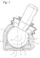
- FIG. 1 a supporting joint according to the prior art is shown in principle in section to illustrate the invention.
- a cover 1 has a dome-shaped inner wall 2 with a support surface on its side facing the interior of the supporting joint.
- a pressure shell 3 with a spherical shape 4 lies between the cover 1 and a ball 5 of a ball pin.
- the pressure shell 3 On its outside or on the side of the pressure shell 3 facing the cover 1, the pressure shell 3 has a spherical or curved surface 6 on which the dome-shaped inner wall 2 of the cover after assembly of the support joint partially abuts, thus providing a support surface for the pressure shell 3.
- the pressure shell 3 has a central bore or recess 7.
- the ball pin is supported with the ball 5 in a housing 8 surrounding it, on the one hand via a bowl-shaped receptacle 11 and, on the other hand, via a support surface of the pressure shell 3, the curvature of which is adapted to the curvature or the radius of the ball on the side of the ball 5 facing the ball is.
- the center line of the support joint is labeled "10".
- the radii of the ball 5, the pressure shell 3 and the cover 1 correspond to one another or are coaxial and the thickness of the pressure shell 3 practically corresponds to the distance between the inner wall 2 of the cover 1 and the ball surface.
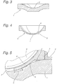
- the solution according to the invention is now shown in FIG. 2 and in particular in the enlarged representations of FIGS. 3 to 5.
- the pressure shell 3 is made of a deformable plastic, so that it deforms under load and no damage As a result, excessive stresses can occur in the material.
- the pressure shell 3 has a greater thickness than the distance between the ball 5 and the inner wall of the cover 1 in the assembled state of the support joint, at least in the overlap or support area provided between the pressure shell 3 and the cover 1.
- the overlap or support area means the area in which the pressure shell 3, with its curved surface 6, bears against the inner wall 2 of the cover 1. This support area is indicated by "9" in FIG. 5 and lies in the radially inner area with respect to the center line 10.
- the radius of curvature of the cover 1 is larger than the outer radius of the pressure shell 3, at least in the support region 9 provided, i.e. the inner wall of the lid 1 is flatter curved.
- the support area 9 is formed in the radially inner area in the form of a wedge-shaped zone, the wedge decreasing radially outward. 5, the length of the support area 9 is indicated by arrows.
- tolerance compensation is achieved in a simple manner. If the ball 5 has its intended diameter, the wedge-shaped zone of the support area 9 is very small. In the case of a larger ball 5, the support area is inevitably somewhat larger, but remains in the area of a small friction radius, whereby the distance of the wedge-shaped zone from the center line 9 of the support joint is meant. In principle, however, the friction radius remains relatively small and, unlike in the prior art according to FIG. 1, does not lie in the radial outer region under high loads.
- the central recess 7 ensures that material of the pressed pressure shell 3 can migrate into this area. In other words, this prevents the pressure shell 3 from having to move radially outwards, which would lead to a corresponding increase in the friction radius and thus to a corresponding fluctuation in the frictional torque.
- the amount of the acting force also drops outwards, since the force becomes smaller and smaller the less the overlap or the support area 9 is with decreasing wedge-shaped zone. Therefore, there are no major effects on the friction torque tolerance in the case of larger overlap or tolerance errors.
- the mounting of the support joint according to the invention takes place in such a way that the bearing shell or support 11 is first inserted into the housing 8, after which the Ball 5 is inserted. Subsequently, the pressure shell 3 is placed on the ball 5 and the cover 1 is placed on the housing 8, the outer radius of the pressure shell 3 then corresponding to the radius or the curvature of the inner wall 2 of the cover 1 in the support region 9 after a pressing operation.
- the cover 1 is fastened to the housing 8 by flanging a protruding edge of the housing 8, so that no further fastening and adjusting devices are necessary to mount the supporting joint according to the invention.
Landscapes
- Engineering & Computer Science (AREA)
- General Engineering & Computer Science (AREA)
- Mechanical Engineering (AREA)
- Physics & Mathematics (AREA)
- Geometry (AREA)
- Pivots And Pivotal Connections (AREA)
- Vehicle Body Suspensions (AREA)
Abstract
Description
- Die Erfindung betrifft ein Traggelenk der im Oberbegriff von Anspruch 1 näher definierten Art.
- Traggelenke dieser Art sind aus der Praxis bekannt. Sie werden beispielsweise in Doppelquerlenkerachsen mit federbelasteten unteren Querlenkern eingebaut. Dabei treten aufgrund der Radaufstandskraft senkrecht zur Fahrbahnoberfläche angreifende Kräfte auf, welche das Traggelenk beispielsweise auf Zug belasten.
- Da diese Belastung, d.h. die angreifenden Zugkräfte, nicht immer gleich groß ist, sind im Inneren des Traggelenkes Einrichtungen für einen Ausgleich des dort vorhandenen Spieles vorzusehen. Als spielausgleichendes Teil wird meist ein Bauteil aus einem verformungsfähigen Werkstoff, meist einem Kunststoff, verwendet. Dieses Bauteil, das meist als Druckschale ausgeführt ist, liegt einerseits am Deckel des Traggelenkes an, gegen den es von der Kugel des Traggelenkes gepreßt wird, andererseits liegt die Druckschale auch an der Gehäusewand des Traggelenkes an. Aufgrund dieses Anliegens an zwei Punkten, also räumlich gesehen an zwei Ringflächen, kann sich die Druckschale zum Spielausgleich nur sehr wenig oder gar nicht verformen, so daß entweder der Spielausgleich unzureichend ist, oder das Traggelenk nur sehr schwer bewegbar ist, weil die Druckschale so dimensioniert ist, daß sehr hohe Reibmomente zwischen der Druckschale und der Kugel des Traggelenkes entstehen.
- Hinzu kommt noch, daß sich das spielausgleichende Bauteil, nämlich die Druckschale, an die Form des Deckels des Gehäuses anpaßt. Insbesondere am äußeren Umfang der Druckschale findet dieser Vorgang statt, so daß beim Einrollieren des Traggelenkgehäuses die Druckschale auf großem Radius auf die Kugel drückt. Das Reibmoment des Gelenkes bzw. die Reibmomenttoleranz wird hierdurch negativ beeinflußt.
- Wenn der Deckel nach innen gedrückt wird, entsteht zusätzlich eine Keilwirkung im Bereich zwischen der Druckschale und der Kugel. Zudem kann bei Druckbelastung noch immer eine axiale Weichheit bzw. Elastizität zwischen der Kugel und dem Gehäuse bzw. der Abstützung auftreten, weil im inneren Bereich bei kleinerem Radius zwischen dem Deckel und der Druckschale ein Freiraum vorhanden ist.
- Eine axiale Weichheit im Gelenk ist jedoch unzulässig, weil Beschädigungen des Traggelenkes anhand einer Spielfreiheit überprüft werden müssen.
- Des weiteren sollten keine großen Reibmomentschwankungen im Traggelenk auftreten, damit das Traggelenk mit möglichst definierter Reibung bewegbar ist.
- In der US-PS 3 401 962 ist ein Gelenk mit einem verdrehbaren teilkugelförmigen Lagerzapfen dargestellt. Auf dem Lagerzapfen liegt ein Zwischenblech auf, das zusammen mit dem Lagerzapfen gegen ein Lagerteil verdreht werden kann (Fig. 4) oder gegen ein Lagerteil direkt (Fig. 1). Das Lagerteil stellt somit ein stehendes Teil gegenüber dem drehbaren Lagerzapfen und gegebenenfalls auch dem Zwischenblech dar. Um einen direkten Kontakt zwischen dem Lagerteil und dem Lagerzapfen oder dem Zwischenblech zu vermeiden und um eine Berührung nur über O-Ringe zu erzielen, ist der Radius der Lagerschale größer als der Radius des Lagerzapfens. Der entstehende Radius dient als berührungsfreier Schmiermittelraum.
- Der vorliegenden Erfindung liegt die Aufgabe zugrunde, ein Traggelenk der eingangs erwähnten Art vorzusehen, das eine möglichst große Toleranzunempfindlichkeit ohne Einstellnotwendigkeit aufweist.
- Erfindungsgemäß wird diese Aufgabe durch die im kennzeichnenden Teil von Anspruch 1 genannten Merkmale gelöst.
- Durch die erfindungsgemäße Wahl der Dicke der Druckschale, welche im unmontierten Zustand größer ist als der Abstand zwischen Kugel und Abstützfläche des Deckels, wird bei der Montage durch eine Pressung der Druckschale auf einfache Art und Weise sichergestellt, daß das Gelenk spielfrei ist und die Reibmomente des Gelenkes bzw. die Reibmomenttoleranzen nicht negativ beeinflußt werden, so daß sich das Traggelenk mit möglichst definierter Reibung bewegen läßt. Das bei der Pressung verdrängte Material der Druckschale kann dabei in die zentrale Ausnehmung ausweichen.
- Vorteilhafte Ausgestaltungen und Weiterbildungen der Erfindung ergeben sich aus den Unteransprüchen und dem nachfolgend anhand der Zeichnung beschriebenen Ausführungsbeispiel.
- Es zeigt:
- Fig. 1
- einen Schnitt durch ein Traggelenk nach dem Stand der Technik;
- Fig. 2
- einen Schnitt durch ein erfindungsgemäßes Traggelenk;
- Fig. 3
- einen Schnitt durch den Deckel eines erfindungsgemäßen Traggelenkes;
- Fig. 4
- einen Schnitt durch die Druckschale eines erfindungsgemäßen Traggelenkes; und
- Fig. 5
- in vergrößerter Darstellung die Einzelheit "V" der Fig. 1.
- In der Fig. 1 ist zur Verdeutlichung der Erfindung ein Traggelenk nach dem Stand der Technik prinzipmäßig im Schnitt dargestellt. Ein Deckel 1 weist auf seiner dem Inneren des Traggelenkes zugewandten Seite eine kalottenförmige Innenwand 2 mit einer Abstützfläche auf. Eine Druckschale 3 mit einer Kalottenform 4 liegt zwischen dem Deckel 1 und einer Kugel 5 eines Kugelzapfens. Auf ihrer Außenseite bzw. auf der zu dem Deckel 1 gerichteten Seite der Druckschale 3 weist diese eine sphärisch bzw. gekrümmte Fläche 6 auf, an der die kalottenförmige Innenwand 2 des Deckels nach der Montage des Traggelenkes teilweise anliegt, und damit eine Abstützfläche für die Druckschale 3 ergibt. Die Druckschale 3 weist eine zentrale Bohrung bzw. Ausnehmung 7 auf.
- Die Abstützung des Kugelzapfens mit der Kugel 5 in einem diesen umgebenden Gehäuse 8 erfolgt zum einen über eine schalenförmige Aufnahme 11 und zum anderen über eine Abstützfläche der Druckschale 3, deren Krümmung auf der der Kugel 5 zugewandten Seite der Krümmung bzw. dem Radius der Kugel angepaßt ist. Die Mittellinie des Traggelenkes ist mit "10" bezeichnet.
- Bei dieser Ausgestaltung des Standes der Technik sind die Radien der Kugel 5, der Druckschale 3 und des Deckels 1 korrespondierend zueinander bzw. koaxial und die Dicke der Druckschale 3 entspricht praktisch dem Abstand zwischen der Innenwand 2 des Deckels 1 und der Kugeloberfläche. Dies bedeutet, daß mit zunehmender Last der Abstützbereich in eine radial äußere, dem Deckelrand nahe Ringzone wandert, mit der Folge eines entsprechend großen Reibradius und eines daraus resultierenden großen Reibmomentes. Wie aus der Fig. 1 ersichtlich ist, kann dabei sogar die Situation entstehen, daß im radialen inneren Bereich ein Freiraum zwischen dem Außendurchmesser der Druckschale, d.h. der Fläche 6, und der Innenwand 2 des Deckels 1 entsteht. Das Reibmoment ist damit toleranzabhängig.
- In der Fig. 2 und insbesondere in den vergrößerten Darstellungen der Fig. 3 bis 5 ist nun die erfindungsgemäße Lösung dargestellt. Die Druckschale 3 ist aus einem verformbaren Kunststoff hergestellt, so daß sie sich unter Belastung verformen und keine Beschädigung in Folge zu hoher Spannungen im Werkstoff auftreten kann. Die Druckschale 3 weist im unmontierten Zustand zumindest in dem vorgesehenen Überdeckungs- bzw. Abstützbereich zwischen Druckschale 3 und Deckel 1 eine größere Dicke auf als der Abstand zwischen der Kugel 5 und der Innenwand des Deckels 1 im montierten Zustand des Traggelenkes.
- Mit Überdeckungs- bzw. Abstützbereich ist dabei der Bereich gemeint, in dem die Druckschale 3 mit ihrer gekrümmten Fläche 6 an der Innenwand 2 des Deckels 1 anliegt. Dieser Abstützbereich ist in der Fig. 5 mit "9" angegeben und liegt im radial inneren Bereich, bezogen auf die Mittellinie 10.
- Der Krümmungsradius des Deckels 1 ist wenigstens in dem vorgesehenen Abstützbereich 9 größer als der Außenradius der Druckschale 3, d.h. die Innenwand des Deckels 1 ist flacher gekrümmt.
- Dies bedeutet, bei der Montage des Traggelenkes erfolgt eine Pressung der Druckschale 3 im inneren Bereich, wobei sich das Material im wesentlichen in die zentrale Ausnehmung 7 verteilt. Auf diese Weise entsteht der Abstützbereich 9 im radial inneren Bereich in Form einer keilförmigen Zone, wobei der Keil radial nach außen zu abnimmt. In der Fig. 5 ist die Länge des Abstützbereiches 9 mit Pfeilen gekennzeichnet. Wie ersichtlich wird damit auf einfache Weise ein Toleranzausgleich erzielt. Weist die Kugel 5 ihren vorgesehenen Durchmesser auf, ist die keilförmige Zone des Abstützbereiches 9 sehr klein. Bei einer größeren Kugel 5 ist der Abstützbereich zwangsweise etwas größer, er verbleibt jedoch im Bereich eines kleinen Reibradiuses, wobei damit der Abstand der keilförmigen Zone von der Mittellinie 9 des Traggelenkes gemeint ist. Grundsätzlich verbleibt der Reibradius jedoch relativ klein und liegt nicht wie beim Stand der Technik gemäß Fig. 1 bei hoher Belastung im radialen äußeren Bereich.
- Bei der Ausgestaltung nach den Fig. 2 bis 5 werden somit höhere Belastungen stets im zentralen Bereich abgefangen. Damit bleibt der Reibradius auch belastungsabhängig und unabhängig von Toleranzen im wesentlichen gleich und damit auch das Reibmoment. Die Belastung entspricht einer entsprechenden Vorspannung aufgrund von Maßtoleranzen.
- Durch die zentrale Ausnehmung 7 wird - wie vorstehend bereits erwähnt - erreicht, daß ein Auswandern von Material der gepreßten Druckschale 3 in diesen Bereich möglich ist. Dies bedeutet, mit anderen Worten, es wird verhindert, daß die Druckschale 3 nach radial außen ausweichen muß, was zu einer entsprechenden Vergrößerung des Reibradius und damit zu einer entsprechenden Schwankung im Reibmoment führen würde. Zwar werden auftretende Kräfte immer weiter nach außen verteilt, allerdings sinkt auch der Betrag der angreifenden Kraft nach außen hin, da die Kraft immer kleiner wird, je geringer die überdeckung bzw. der Abstützbereich 9 bei abnehmender keilförmiger Zone ist. Daher ergeben sich keine größeren Auswirkungen auf die Reibmomenttoleranz bei größeren Überdeckungs- bzw. Toleranzfehlern.
- Die Bildung des keilförmigen Abstützbereiches im inneren Bereich kann auf zwei verschiedenen Wegen bezüglich der unterschiedlichen Radien zwischen der Druckschale und dem Deckel erreicht werden, nämlich:
- 1. Wie in den Fig. 2 bis 5 dargestellt: Der Radius der Innenwand des Deckels ist größer bzw. flacher. Auf diese Weise wird bei einem herkömmlichen Gelenk mit einer Kugel eine normale Druckschale verwendet und der Deckel 1 entsprechend abgeändert bezüglich eines entsprechend flacheren Verlaufes seiner Innenwandung. Mit anderen Worten, der Mittelpunkt des Radius des Deckels ist versetzt zum Kugelmittelpunkt. Nur die beiden Radien der Druckschale 3 haben den gleichen Mittelpunkt wie die Kugel 5.
- 2. Die Innenwand des Deckels 2 liegt konzentrisch zur Kugel 5. In diesem Fall muß dann jedoch, um die Abstützfläche mit der Keilform im inneren Bereich zu erhalten, die Dicke der Druckschale 3 variiert werden. Durch eine entsprechende Radiusänderung wird die Druckschale 3 nunmehr im inneren Bereich dicker gemacht. Der Erfolg davon ist, daß dann bei der Montage ebenfalls die Druckschale 3 in der Mitte keilförmig gedrückt wird und außen der Freiraum zwischen der Druckschale 3 und dem Deckel 2 verbleibt.
- Dies bedeutet, die erfindungsgemäße Lösung kann zum einen von der Druckschalenseite her durch eine dickere Ausbildung im inneren Bereich oder von der Deckelseite her mit einem flacheren Radius der Innenwand erreicht werden.
- Die Montage des erfindungsgemäßen Traggelenkes erfolgt dergestalt, daß zuerst die Lagerschale bzw. Abstützung 11 in das Gehäuse 8 eingelegt wird, wonach dann die Kugel 5 eingelegt wird. Anschließend wird die Druckschale 3 an die Kugel 5 gelegt und der Deckel 1 an dem Gehäuse 8 angelegt, wobei dann nach einem Anpreßvorgang der Außenradius der Druckschale 3 dem Radius bzw. der Krümmung der Innenwand 2 des Deckels 1 im Abstützbereich 9 entspricht.
- Die Befestigung des Deckels 1 an dem Gehäuse 8 erfolgt durch Umbördeln eines überstehenden Randes des Gehäuses 8, so daß keine weiteren Befestigungs- und Einstelleinrichtungen notwendig sind, um das erfindungsgemäße Traggelenk zu montieren.
Claims (3)
- Traggelenk mit einem Gehäuse (8) und einem über eine Abstützung in diesem gehaltenen Kugelzapfen, wobei die Abstützung zapfenseitig eine schalenförmige Aufnahme (11), gegenüberliegend zum Zapfen eine Druckschale (3) mit einer Ausnehmung (7) in ihrem zentralen Abstützbereich und rückseitig zur Druckschale (3) einen diese abstützenden Deckel (1) aufweist, dessen Abstützfläche in ihrer Krümmung der Krümmung der Kugel im wesentlichen entspricht,
dadurch gekennzeichnet, daß, bezogen auf das montierte Gelenk, die im unmontierten Zustand gemessene Dicke der Druckschale (3) im zentralen Abstützbereich (9) größer als der Abstand zwischen der Kugel (5) und der Abstützfläche (2) des Deckels (1) ist. - Traggelenk nach Anspruch 1,
dadurch gekennzeichnet, daß in unmontiertem Zustand des Traggelenkes die Krümmung des Deckels (1) wenigstens im Abstützbereich (9) einen größeren Radius aufweist als ein Außenradius der Druckschale (3), welcher der Krümmung des Deckels (1) benachbart liegt, und daß in montiertem Zustand des Traggelenkes wenigstens im Abstützbereich (9) durch Verpressung der Druckschale (3) die Radien gleich groß sind. - Traggelenk nach Anspruch 1 oder 2,
dadurch gekennzeichnet, daß nach radial außen, bezogen auf die Druckschale (3), die Größe des Abstandes zwischen der Kugel (5) und der Abstützfläche des Deckels (1) die Dicke der Druckschale (3) überschreitet.
Applications Claiming Priority (2)
| Application Number | Priority Date | Filing Date | Title |
|---|---|---|---|
| DE4401639A DE4401639C2 (de) | 1994-01-21 | 1994-01-21 | Traggelenk |
| DE4401639 | 1994-01-21 |
Publications (2)
| Publication Number | Publication Date |
|---|---|
| EP0664408A1 true EP0664408A1 (de) | 1995-07-26 |
| EP0664408B1 EP0664408B1 (de) | 1999-03-10 |
Family
ID=6508347
Family Applications (1)
| Application Number | Title | Priority Date | Filing Date |
|---|---|---|---|
| EP94120373A Expired - Lifetime EP0664408B1 (de) | 1994-01-21 | 1994-12-22 | Kugelgelenk |
Country Status (5)
| Country | Link |
|---|---|
| US (1) | US6386787B1 (de) |
| EP (1) | EP0664408B1 (de) |
| JP (1) | JPH07208451A (de) |
| KR (1) | KR0180957B1 (de) |
| DE (2) | DE4401639C2 (de) |
Cited By (1)
| Publication number | Priority date | Publication date | Assignee | Title |
|---|---|---|---|---|
| WO2002036972A3 (en) * | 2000-10-31 | 2002-09-06 | Gerber Coburn Optical Inc | Spherical bearing |
Families Citing this family (10)
| Publication number | Priority date | Publication date | Assignee | Title |
|---|---|---|---|---|
| DE29708162U1 (de) * | 1997-05-09 | 1997-07-17 | Lemförder Metallwaren AG, 49448 Lemförde | Radialkugelgelenk für Kraftfahrzeug |
| DE19748117C2 (de) | 1997-10-31 | 2002-11-14 | Zf Lemfoerder Metallwaren Ag | Kugelzapfen |
| JP2003529024A (ja) * | 2000-03-28 | 2003-09-30 | ルーク ラメレン ウント クツプルングスバウ ベタイリグングス コマンディートゲゼルシャフト | 変速機を備えた自動車 |
| US6533490B2 (en) * | 2001-01-05 | 2003-03-18 | American Axle & Manufacturing, Inc. | Isolation ball joint for steering and suspension |
| BR0103298B1 (pt) * | 2001-06-28 | 2010-08-10 | construção de tampa para articulação esférica. | |
| DE102007016713B4 (de) | 2007-04-04 | 2011-07-14 | Saint-Gobain Performance Plastics Pampus GmbH, 47877 | Gelenklager |
| DE102008049747A1 (de) | 2008-09-30 | 2010-04-01 | Saint-Gobain Performance Plastics Pampus Gmbh | Schwingungsdämpfendes Gleitlager-Verbundmaterial und Gleitlagerbuchse und Gleitlageranordnung |
| DE102013220038A1 (de) * | 2013-10-02 | 2015-04-02 | Zf Friedrichshafen Ag | Kugelgelenk mit belastungsoptimierter Kugelschale |
| DE102015219899B4 (de) * | 2015-10-14 | 2020-01-30 | Continental Automotive Gmbh | Stelleinrichtung zum Betätigen eines Stellglieds eines Turboladers sowie Turbolader für eine Brennkraftmaschine |
| KR101815146B1 (ko) * | 2016-02-19 | 2018-03-15 | 주식회사 일진 | 볼 조인트 및 그 제작 방법 |
Citations (7)
| Publication number | Priority date | Publication date | Assignee | Title |
|---|---|---|---|---|
| US2917334A (en) * | 1956-11-13 | 1959-12-15 | Gen Motors Corp | Ball joint |
| GB861976A (en) * | 1958-04-24 | 1961-03-01 | Eng Productions Clevedon Ltd | Improvements in or relating to ball and socket joints |
| US3545797A (en) * | 1968-08-22 | 1970-12-08 | Barmatic Machines Inc | Ball joint with plastic seat |
| FR2250042A1 (de) * | 1973-11-06 | 1975-05-30 | Ishikawa Tekko Kk | |
| GB2038928A (en) * | 1978-11-28 | 1980-07-30 | Armstrong Patents Co Ltd | Improved Ball Joint |
| EP0213314A2 (de) * | 1985-08-28 | 1987-03-11 | TRW Ehrenreich GmbH & Co. KG | Kugelgelenk |
| EP0345452A2 (de) * | 1988-06-08 | 1989-12-13 | TRW Fahrwerksysteme GmbH & Co. KG | Verfahren zum Herstellen von Kugelgelenken |
Family Cites Families (23)
| Publication number | Priority date | Publication date | Assignee | Title |
|---|---|---|---|---|
| US3375027A (en) * | 1964-04-24 | 1968-03-26 | Ulderup Jurgen | Universal joint construction having housing of epoxy resin |
| DE1904381U (de) * | 1964-07-16 | 1964-11-12 | Ehrenreich & Cie A | Kugelgelenk fuer kraftfahrzeuge. |
| DE1525084A1 (de) * | 1965-11-27 | 1969-07-03 | Ehrenreich & Cie A | Kugelgelenk |
| US3401962A (en) * | 1965-12-06 | 1968-09-17 | Moog Industries Inc | Wear-compensating movable joint device |
| AT278544B (de) * | 1966-12-22 | 1970-02-10 | Ehrenreich & Cie A | Kugelgelenk für Lenkgestänge von Kraftfahrzeugen, insbesondere für Zugbelastungen |
| US3832668A (en) * | 1972-03-31 | 1974-08-27 | Westinghouse Electric Corp | Silicon carbide junction thermistor |
| JPS513853B2 (de) * | 1972-06-14 | 1976-02-06 | ||
| JPS5328576B2 (de) * | 1973-07-02 | 1978-08-15 | ||
| JPS5137365A (de) * | 1974-09-27 | 1976-03-29 | Toshio Hata | |
| DE2757198A1 (de) * | 1977-12-22 | 1979-06-28 | Ehrenreich Gmbh & Co Kg A | Kugelgelenk |
| DE3018187A1 (de) * | 1980-05-13 | 1981-11-19 | Daimler-Benz Ag, 7000 Stuttgart | Kugelgelenk und verfahren zu dessen herstellung |
| JPS59121332A (ja) * | 1982-12-28 | 1984-07-13 | Konishiroku Photo Ind Co Ltd | 写真用カプラ− |
| DE3315658C2 (de) * | 1983-04-29 | 1986-10-09 | Lemförder Metallwaren AG, 2844 Lemförde | Kugelgelenk, insbesondere Spurstangengelenk |
| JPH0781580B2 (ja) | 1986-06-16 | 1995-08-30 | 武蔵精密工業株式会社 | ボ−ルジヨイント |
| DE3623542C1 (de) * | 1986-07-12 | 1987-12-17 | Trw Ehrenreich Gmbh | Kugelgelenk |
| GB8617540D0 (en) | 1986-07-17 | 1986-08-28 | British Petroleum Co Plc | Leaf spring |
| JPS6372913A (ja) * | 1986-09-16 | 1988-04-02 | Musashi Seimitsu Ind Co Ltd | ボ−ルジヨイント |
| JPH01100921A (ja) | 1987-10-13 | 1989-04-19 | Sumitomo Metal Ind Ltd | プラズマエッチング装置 |
| DE3741347C1 (de) * | 1987-12-07 | 1989-05-11 | Trw Ehrenreich Gmbh | Befestigung und Verfahren zur Befestigung eines Dichtungsbalges am Gelenkgehaeuse eines Kugelgelenkes |
| US4875794A (en) * | 1987-12-23 | 1989-10-24 | Dana Corporation | Preloaded steering ball joint assembly and method |
| JP2510261Y2 (ja) * | 1988-06-06 | 1996-09-11 | リズム自動車部品製造 株式会社 | ボ―ルジョイントのソケット |
| DE9304897U1 (de) * | 1993-03-31 | 1993-06-03 | P.C. Turck GmbH & Co. KG, 58507 Lüdenscheid | Kugelgelenk |
| JP2598449Y2 (ja) * | 1993-08-06 | 1999-08-09 | 株式会社ソミック石川 | ボールジョイント |
-
1994
- 1994-01-21 DE DE4401639A patent/DE4401639C2/de not_active Expired - Fee Related
- 1994-12-22 DE DE59407922T patent/DE59407922D1/de not_active Expired - Fee Related
- 1994-12-22 EP EP94120373A patent/EP0664408B1/de not_active Expired - Lifetime
-
1995
- 1995-01-20 JP JP7038932A patent/JPH07208451A/ja active Pending
- 1995-01-20 KR KR1019950000880A patent/KR0180957B1/ko not_active Expired - Fee Related
-
1996
- 1996-08-13 US US08/689,681 patent/US6386787B1/en not_active Expired - Fee Related
Patent Citations (7)
| Publication number | Priority date | Publication date | Assignee | Title |
|---|---|---|---|---|
| US2917334A (en) * | 1956-11-13 | 1959-12-15 | Gen Motors Corp | Ball joint |
| GB861976A (en) * | 1958-04-24 | 1961-03-01 | Eng Productions Clevedon Ltd | Improvements in or relating to ball and socket joints |
| US3545797A (en) * | 1968-08-22 | 1970-12-08 | Barmatic Machines Inc | Ball joint with plastic seat |
| FR2250042A1 (de) * | 1973-11-06 | 1975-05-30 | Ishikawa Tekko Kk | |
| GB2038928A (en) * | 1978-11-28 | 1980-07-30 | Armstrong Patents Co Ltd | Improved Ball Joint |
| EP0213314A2 (de) * | 1985-08-28 | 1987-03-11 | TRW Ehrenreich GmbH & Co. KG | Kugelgelenk |
| EP0345452A2 (de) * | 1988-06-08 | 1989-12-13 | TRW Fahrwerksysteme GmbH & Co. KG | Verfahren zum Herstellen von Kugelgelenken |
Cited By (1)
| Publication number | Priority date | Publication date | Assignee | Title |
|---|---|---|---|---|
| WO2002036972A3 (en) * | 2000-10-31 | 2002-09-06 | Gerber Coburn Optical Inc | Spherical bearing |
Also Published As
| Publication number | Publication date |
|---|---|
| EP0664408B1 (de) | 1999-03-10 |
| KR0180957B1 (ko) | 1999-05-15 |
| DE4401639C2 (de) | 1997-03-20 |
| KR950023868A (ko) | 1995-08-18 |
| JPH07208451A (ja) | 1995-08-11 |
| DE4401639A1 (de) | 1995-08-03 |
| US6386787B1 (en) | 2002-05-14 |
| DE59407922D1 (de) | 1999-04-15 |
Similar Documents
| Publication | Publication Date | Title |
|---|---|---|
| EP2631499B1 (de) | Kugelgelenk | |
| DE4401639C2 (de) | Traggelenk | |
| EP0916798B1 (de) | Halterung für plattenförmige Bauteile | |
| DE102016206863A1 (de) | Axialkugelgelenk und längeneinstellbarer Zweipunktlenker mit einem solchen Axialkugelgelenk | |
| DE2729064C2 (de) | Symmetrische flache Kraftmeßzelle | |
| DE4401639C9 (de) | Traggelenk | |
| DE102015104925A1 (de) | Kugelgewindetrieb und damit ausgestattete Lenkung eines Kraftfahrzeugs | |
| DE29710578U1 (de) | Einknüpflager | |
| EP0785370A1 (de) | Kreuzgelenkanordnung für eine Gelenkwelle | |
| DE4428870C1 (de) | Gummi-Gelenklager | |
| DE4304775C2 (de) | Gelenklager | |
| DE102017216488A1 (de) | Radialkugelgelenk für ein Lenkerbauteil eines Kraftfahrzeugs | |
| DE4419954C2 (de) | Zapfengelenk | |
| DE102009031738B4 (de) | Kugelgelenk | |
| DE10002757B4 (de) | Kugelgelenk | |
| EP0751310B1 (de) | Kugelgelenk | |
| WO2001036252A1 (de) | Achsschenkel mit minimaler wandstärkendifferenz | |
| DE19510761B4 (de) | Anlaufscheibe für Gelenkkreuzbüchsen | |
| DE10258987B4 (de) | Gelenklager | |
| DE19851530C2 (de) | Kreuzgelenkanordnung für den Einsatz in Gelenkwellen | |
| DE4301178C2 (de) | Kreuzzapfengelenk einer zur Übertragung hoher Drehmomente geeigneten Gelenkwelle | |
| DE2632289C2 (de) | Klappenventil | |
| DE3920683C2 (de) | Kugelgelenkanordnung | |
| EP1756439A1 (de) | Zentralgelenk für einen dreieckslenker von kraftfahrzeugen | |
| EP0750123A1 (de) | Kugelgelenk |
Legal Events
| Date | Code | Title | Description |
|---|---|---|---|
| PUAI | Public reference made under article 153(3) epc to a published international application that has entered the european phase |
Free format text: ORIGINAL CODE: 0009012 |
|
| 17P | Request for examination filed |
Effective date: 19950509 |
|
| AK | Designated contracting states |
Kind code of ref document: A1 Designated state(s): DE FR GB IT |
|
| 17Q | First examination report despatched |
Effective date: 19970626 |
|
| RAP1 | Party data changed (applicant data changed or rights of an application transferred) |
Owner name: DAIMLER-BENZ AKTIENGESELLSCHAFT |
|
| GRAG | Despatch of communication of intention to grant |
Free format text: ORIGINAL CODE: EPIDOS AGRA |
|
| GRAG | Despatch of communication of intention to grant |
Free format text: ORIGINAL CODE: EPIDOS AGRA |
|
| GRAH | Despatch of communication of intention to grant a patent |
Free format text: ORIGINAL CODE: EPIDOS IGRA |
|
| GRAH | Despatch of communication of intention to grant a patent |
Free format text: ORIGINAL CODE: EPIDOS IGRA |
|
| GRAA | (expected) grant |
Free format text: ORIGINAL CODE: 0009210 |
|
| ITF | It: translation for a ep patent filed | ||
| AK | Designated contracting states |
Kind code of ref document: B1 Designated state(s): DE FR GB IT |
|
| RAP2 | Party data changed (patent owner data changed or rights of a patent transferred) |
Owner name: DAIMLERCHRYSLER AG |
|
| GBT | Gb: translation of ep patent filed (gb section 77(6)(a)/1977) |
Effective date: 19990323 |
|
| REF | Corresponds to: |
Ref document number: 59407922 Country of ref document: DE Date of ref document: 19990415 |
|
| ET | Fr: translation filed | ||
| PLBE | No opposition filed within time limit |
Free format text: ORIGINAL CODE: 0009261 |
|
| STAA | Information on the status of an ep patent application or granted ep patent |
Free format text: STATUS: NO OPPOSITION FILED WITHIN TIME LIMIT |
|
| 26N | No opposition filed | ||
| PGFP | Annual fee paid to national office [announced via postgrant information from national office to epo] |
Ref country code: GB Payment date: 20011116 Year of fee payment: 8 |
|
| PGFP | Annual fee paid to national office [announced via postgrant information from national office to epo] |
Ref country code: FR Payment date: 20011211 Year of fee payment: 8 |
|
| REG | Reference to a national code |
Ref country code: GB Ref legal event code: IF02 |
|
| REG | Reference to a national code |
Ref country code: FR Ref legal event code: TP |
|
| PG25 | Lapsed in a contracting state [announced via postgrant information from national office to epo] |
Ref country code: GB Free format text: LAPSE BECAUSE OF NON-PAYMENT OF DUE FEES Effective date: 20021222 |
|
| GBPC | Gb: european patent ceased through non-payment of renewal fee |
Effective date: 20021222 |
|
| PG25 | Lapsed in a contracting state [announced via postgrant information from national office to epo] |
Ref country code: FR Free format text: LAPSE BECAUSE OF NON-PAYMENT OF DUE FEES Effective date: 20030901 |
|
| REG | Reference to a national code |
Ref country code: FR Ref legal event code: ST |
|
| PG25 | Lapsed in a contracting state [announced via postgrant information from national office to epo] |
Ref country code: IT Free format text: LAPSE BECAUSE OF NON-PAYMENT OF DUE FEES Effective date: 20051222 |
|
| PGFP | Annual fee paid to national office [announced via postgrant information from national office to epo] |
Ref country code: DE Payment date: 20070102 Year of fee payment: 13 |
|
| PG25 | Lapsed in a contracting state [announced via postgrant information from national office to epo] |
Ref country code: DE Free format text: LAPSE BECAUSE OF NON-PAYMENT OF DUE FEES Effective date: 20080701 |