EP0660906B1 - Dispositif pour amortir les vibrations et le bruit, pour des installations hydrauliques - Google Patents
Dispositif pour amortir les vibrations et le bruit, pour des installations hydrauliques Download PDFInfo
- Publication number
- EP0660906B1 EP0660906B1 EP94918822A EP94918822A EP0660906B1 EP 0660906 B1 EP0660906 B1 EP 0660906B1 EP 94918822 A EP94918822 A EP 94918822A EP 94918822 A EP94918822 A EP 94918822A EP 0660906 B1 EP0660906 B1 EP 0660906B1
- Authority
- EP
- European Patent Office
- Prior art keywords
- envelope
- runs
- flow
- flexible material
- water
- Prior art date
- Legal status (The legal status is an assumption and is not a legal conclusion. Google has not performed a legal analysis and makes no representation as to the accuracy of the status listed.)
- Expired - Lifetime
Links
- XLYOFNOQVPJJNP-UHFFFAOYSA-N water Substances O XLYOFNOQVPJJNP-UHFFFAOYSA-N 0.000 claims description 54
- 238000009434 installation Methods 0.000 claims description 30
- 239000000463 material Substances 0.000 claims description 24
- 239000002775 capsule Substances 0.000 claims description 17
- 239000012528 membrane Substances 0.000 claims description 6
- 230000002093 peripheral effect Effects 0.000 claims description 6
- 238000004891 communication Methods 0.000 claims description 3
- 238000013016 damping Methods 0.000 description 16
- 230000009471 action Effects 0.000 description 9
- 230000000694 effects Effects 0.000 description 3
- 230000035939 shock Effects 0.000 description 3
- 208000031968 Cadaver Diseases 0.000 description 2
- 230000008901 benefit Effects 0.000 description 2
- 230000007246 mechanism Effects 0.000 description 2
- 238000000034 method Methods 0.000 description 2
- 230000000737 periodic effect Effects 0.000 description 2
- 239000006096 absorbing agent Substances 0.000 description 1
- 238000004026 adhesive bonding Methods 0.000 description 1
- 230000005540 biological transmission Effects 0.000 description 1
- 239000013536 elastomeric material Substances 0.000 description 1
- 230000004907 flux Effects 0.000 description 1
- 230000001939 inductive effect Effects 0.000 description 1
- 238000012986 modification Methods 0.000 description 1
- 230000004048 modification Effects 0.000 description 1
- 230000010355 oscillation Effects 0.000 description 1
- 238000007789 sealing Methods 0.000 description 1
- 238000003466 welding Methods 0.000 description 1
Images

Classifications
-
- F—MECHANICAL ENGINEERING; LIGHTING; HEATING; WEAPONS; BLASTING
- F16—ENGINEERING ELEMENTS AND UNITS; GENERAL MEASURES FOR PRODUCING AND MAINTAINING EFFECTIVE FUNCTIONING OF MACHINES OR INSTALLATIONS; THERMAL INSULATION IN GENERAL
- F16K—VALVES; TAPS; COCKS; ACTUATING-FLOATS; DEVICES FOR VENTING OR AERATING
- F16K47/00—Means in valves for absorbing fluid energy
- F16K47/02—Means in valves for absorbing fluid energy for preventing water-hammer or noise
- F16K47/026—Means in valves for absorbing fluid energy for preventing water-hammer or noise preventing noise in a single handle mixing valve
-
- Y—GENERAL TAGGING OF NEW TECHNOLOGICAL DEVELOPMENTS; GENERAL TAGGING OF CROSS-SECTIONAL TECHNOLOGIES SPANNING OVER SEVERAL SECTIONS OF THE IPC; TECHNICAL SUBJECTS COVERED BY FORMER USPC CROSS-REFERENCE ART COLLECTIONS [XRACs] AND DIGESTS
- Y10—TECHNICAL SUBJECTS COVERED BY FORMER USPC
- Y10T—TECHNICAL SUBJECTS COVERED BY FORMER US CLASSIFICATION
- Y10T137/00—Fluid handling
- Y10T137/8593—Systems
- Y10T137/86493—Multi-way valve unit
- Y10T137/86549—Selective reciprocation or rotation
-
- Y—GENERAL TAGGING OF NEW TECHNOLOGICAL DEVELOPMENTS; GENERAL TAGGING OF CROSS-SECTIONAL TECHNOLOGIES SPANNING OVER SEVERAL SECTIONS OF THE IPC; TECHNICAL SUBJECTS COVERED BY FORMER USPC CROSS-REFERENCE ART COLLECTIONS [XRACs] AND DIGESTS
- Y10—TECHNICAL SUBJECTS COVERED BY FORMER USPC
- Y10T—TECHNICAL SUBJECTS COVERED BY FORMER US CLASSIFICATION
- Y10T137/00—Fluid handling
- Y10T137/8593—Systems
- Y10T137/86493—Multi-way valve unit
- Y10T137/86815—Multiple inlet with single outlet
Definitions
- the subject of the present invention is a device intended to absorb vibrations and noise produced in a hydraulic installation.
- Hydraulic devices including mixing valves for hot and cold water, give rise under certain operating conditions to vibrations, which are mainly due to phenomena of cavitation as well as sudden deviations imposed on water flows, and these vibrations are transmitted by water, through the supply pipes, to the main pipes of the installation, and finally they are transmitted to the environment in the form of noise.
- the vibrations are harmful, and noise should be kept below certain maximum values which are sometimes imposed by regulations.
- the means used usually to limit the noise of an installation is to compensate for the incompressibility of water by including along the passage of water from elastically flexible regions formed by air pockets enclosed in envelopes of flexible material, usually elastomeric.
- these pockets of air are defined by annular envelopes having a cross section C, arranged in the passages traversed by the water between the arrivals at body of a tap and a fixed plate controlling the flow.
- air pockets are defined by tubular casings with wings, the shape of which is more complicated than the preceding envelopes, which are also arranged in the passages traversed by water between arrivals at the body of a tap and a fixed plate controlling the flow.
- air pockets are defined by tubular envelopes arranged in channels formed for the arrival of water in the body of a tap.
- other provisions are known in this purpose, and they can be provided either in the body of a tap or in the S-fittings usually used for the connection of a tap to water intakes inserted in a wall.
- the damping action is due to the flexibility elastic air trapped in the pockets, which is separated from water by the envelopes of elastomeric material which contain the air pockets.
- the presence of these envelopes hinders the action of the pockets air, however it is necessary to prevent air from the pockets is carried away, in time, by the flow of water.
- To achieve action high damping by reducing the obstacle represented by envelopes it is necessary that these show great flexibility, so that they are thin. But if an envelope with the known way would be very thin, the flow of water that licks it would exert on it dynamic actions by inducing vibrations, which are harmful, and ultimately could damage the envelope.
- a device intended to absorb pressure shock in a hydraulic installation includes a casing of flexible material which encloses an air pocket and which is arranged in contact with the water of the hydraulic installation, said envelope being arranged in a derived space communicating with the spaces traversed by the flow of water without being traversed itself by this flow.
- This type of device is intended to suppress pressure shocks due to the rapid closing of a valve, and therefore isolated, intense pressure strokes and impulsive.
- a capacity air pocket is necessary. considerable, and the result is a large device.
- a device of these dimensions could not absorb vibrations and noises, whose intensity is reduced and the frequency of oscillation is relatively high and therefore cannot be absorbed by large capacity air pockets.
- the present invention relates exclusively to depreciation vibration and noise, and in no way suppressing the requirement regarding the dimensions of the air pockets is opposite to that according to document EP-A-0,249,067.
- the main purpose of the present invention is to rationalize the use air pockets enclosed in envelopes of flexible material, exclusively for the purpose of dampening the vibrations and noise of an installation hydraulic.
- An object of the invention is to achieve a more effective damping action than that obtained usually.
- Another object of the invention is to make possible the installation of an envelope enclosing an air pocket even where the place to provision is particularly limited, and therefore, in particular, in connection with a faucet cartridge.
- Another object of the invention is to make possible the provisions of the envelopes containing air pockets, in which the envelopes cannot be put in vibration or be damaged by the water flow on which it is exerted the damping action.
- the device according to the invention can be produced in forms different.
- a device intended to dampen vibrations and noise produced in a hydraulic installation comprising at least one casing of flexible material which encloses an air pocket and which is arranged in contact with the water of the hydraulic system, in which said envelope is arranged in a derived space, which communicates with the spaces traversed by the water flow, but is not itself traversed in appreciable measure by this flow, and in which said envelope of material flexible has a mainly tubular cylindrical shape and is arranged between an internal tubular member traversed by the water flow and an external cylindrical wall, said air pocket being defined on one side of said envelope, and said derived space being defined on the other side of said envelope, is characterized in that said envelope of flexible material co-operates, to enclose said air pocket, with said internal tubular member, on which the envelope is inserted.
- said envelope of flexible material has a semi-toroidal shape.
- said internal tubular member extends over a length somewhat shorter than that of said cylindrical wall external, thus providing at its end a communication passage between the internal space of said tubular member, which is traversed by the water flow, and the space between said internal tubular member and said outer wall, including said derivative space not traversed by the flow.
- said internal tubular member is a part a member of the hydraulic installation, such as a rigid supply pipe or part of a fitting, traversed by the flow, or said internal tubular member is a member made separately and applied to a member of the hydraulic installation, traversed by the flow.
- a device intended to dampen the vibrations and noise produced in a hydraulic installation of the type comprising at least one envelope of flexible material which encloses an air pocket and which is arranged in contact with the water of the hydraulic system, in which said envelope is arranged in a derived space, which communicates with the spaces traversed by the water flow, but is not traversed itself appreciably able by this flow, and in which said envelope of flexible material has substantially a capsule shape, with a thin wall acting as a membrane, and a wall peripheral, is characterized in that said envelope in the form of capsule is arranged in a side derivative space at a formed passage in an intermediate member intended to be interposed between the bottom of a valve body and the bottom of a cartridge; or else she is willing in a side derivative space at a passage formed in the bottom of a cartridge; or it is arranged in a derivative space from side to a passage of the fixed plate of a cartridge.
- FIG. 1 there is illustrated in section one valve body 1, having a bottom bottom 2 with openings 3 and 4 for the entry of hot and cold water, and closed at the top by a cover 5 which maintains in position in the interior of the body 1 a cartridge 6, provided with a control lever 7.
- the cartridge 6 comprises mechanisms which, under the control of the lever 7, actuated by the user, adjust the mixing ratio between hot water and cold water, as well as the amount of mixed water delivered. These mechanisms can be of any kind known per se, and therefore they do not are neither described nor shown.
- the cartridge also has a flow passage, not shown, and it is installed in the body 1 of the tap with suitable seals 10 which establish the seal with respect to the background 2.
- the tap shown in Figure 1 is of the type supplied by rigid pipes 11 and 12 ending in the bottom 2.
- damping devices according to the invention are partially associated with supply pipes 11 and 12 themselves. These pipes are sized from lot to extend as far as neighbor from the upper end of the openings 3 and 4 from the bottom 2, and they are provided with threaded sockets, 13 and 14 respectively, for their connection at the bottom 2.
- envelopes, 15 and 16 respectively are inserted on the ends of pipes 11 and 12, which arrive beyond the sockets 13 and 14 in the interior of the openings 3 and 4 inserted envelopes, 15 and 16 respectively, of material flexible, preferably elastomeric, which contain between their own walls and the walls of the pipes 11 and 12 of the air pockets, 17 and 18 respectively.
- envelopes 15 and 16 have an outside diameter smaller (although only a little) than the diameter of the openings 3 and 4, so that they define spaces, respectively 19 and 20, surrounding the envelopes 15 and 16.
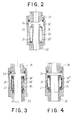
- a connecting member has a hollow body 21 with a bottom 22 threaded to be connected to part of the installation hydraulic, and with a cover 25 in turn threaded to be connected to another part of the hydraulic installation; the flow of the installation therefore runs through connection 21-25.
- a chamber 23 crossed until almost to its end by a section of tube 24 secured to the bottom 22.
- an envelope 26 which in this case has a semi-toroidal shape.
- this device acts, to dampen vibrations and. noise in a way identical to that described in relation to Figure 1.
- the fitting can be inserted between all parts of a hydraulic installation, and, of course, the means it includes for its connection could be different from the threads shown for the bottom 22 and for the cover 25. Note that the water flow can travel the connection, indifferently, in the direction which according to the figure goes from the bottom upwards, or in the opposite direction.
- the casing 26 ' has a semi-toroidal shape with a section at C, and it encloses the air pocket 27 between its own surface and the tube section 24.
- the latter preferably comprises, near its end, a widening, 24 'to hold the envelope in position 26 '.
- Figures 3 and 4 show similar fittings to the following FIG. 2, but in which the section of tube 24 "is produced separately and applied to the bottom 22, instead of being made in one piece with the background itself. This makes it easier to machine the section of 24 "tube and, in particular, allows for seats therein in which the widened, upper and lower edges engage, of the 26 "enclosure. Operation remains identical to operation of the device according to FIG. 2.
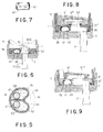
- FIG. 7 shows an embodiment in which the envelope, indicated as a whole by the number 41, can have with advantage of a capsule structure shown in section, with a thin part 42 constituting a membrane (which is the active part damping effects), a peripheral support wall 43 (which may have any suitable thickness) and an edge 44 directed towards the interior.
- the peripheral wall 43 ensures the sealing of such a cover, installed in a corresponding hollow seat, while the edge 44 maintains and also increases the seal when the thin part 42 forming a membrane is deformed by the action of the water pressure.
- Figures 5 and 6 show an intermediate member intended to be interposed between the bottom 2 of a valve body 1 and the bottom of a cartridge 6, to dampen vibrations and noise produced by the tap.
- the intermediate member 50 has passages 51 and 52 which correspond to the supply pipes 11 and 12 ending in the bottom 2 of valve body 1, as well as inlet passages 8 and 9 of the cartridge 6, and these passages 51 and 52 communicate with spaces derivatives 59 and 60 in which capsule envelopes are installed 41 and 41 'similar to those according to Figure 7.
- a seal 61 shaped appropriately defines and separates spaces 51, 59 and 52, 60.
- the operation is still identical to the operation explained with reference to FIG. 1, despite the big difference in the embodiment.
- the layout derived spaces 59 and 60 next to passages 52 and 52 authorizes installation of shock absorbers without requiring any appreciable increase in the length of the valve body 1, allowing thus the installation of the damping devices which, according to the known technique would not be possible, as already said in the preamble.
- intermediate member 50 can be used to connect supply lines 11 and 12 and cartridge inlets 8 and 9, which do not face each other; indeed, there is no difficulty in making the intermediate member 50 so as to connect between them displaced passages with respect to the other.
- Figure 8 shows how the arrangement according to Figure 6 can also be made in the bottom 56 itself of the cartridge 6.
- This bottom includes, for each flow path (i.e., either for hot water, for cold water) a passage 51 'which corresponds to a tubing supply 11, and a passage 51 "which corresponds to a passage 6" of the fixed plate 6 'of the cartridge 6; these passages 51 'and 51 "communicate between them and with the derived space 59 in which the envelope is located in capsule 41 containing the air pocket 40.
- the operation remains identical to the operation already explained.
- this figure give a concrete example of what was said about Figures 5 and 6 about the possibility of connecting supply lines to each other and cartridge inlets (in this case, the passages of the fixed plate of the cartridge) which are not in line.
- Figure 9 shows as the arrangement according to Figure 6 can be carried out even in the fixed plate 6 ', itself, of the cartridge 6.
- the parts which according to figure 8 were carried out or installed in the bottom 56 of the cartridge 6 are now made or installed in the fixed plate 6 'of the cartridge.
- the passage 51 "then forms one of the passages presented by the fixed plate 6 ', which co-operate with the movable plate 6 ° of the cartridge 6.
- the capsule envelope which encloses the air pocket has been shown to be inserted in a seat corresponding hollow.
- this envelope in capsule could also be mounted in a different way on a support, for example by gluing, welding or inserting it as a cap on a support or a connection collar.
- the capsule envelope can also be made in closed form, and in this case she contains an air pocket without co-operating with any other part.
- the envelope containing the air pocket must be made of a flexible material: this is the essential characteristic that the material should show. It is however preferable that said material is as elastic and, more particularly, that it is a material elastomeric.
- the derivative space in which is installed an envelope containing an air pocket intended to carry out amortization can be achieved either in any part of a faucet or faucet cartridge, either in a fitting or in a section of pipeline, or again, in general, in any part of a hydraulic system, which is in communication with the spaces traversed by the flow, in which we want to dampen the vibrations and noise.
Landscapes
- Engineering & Computer Science (AREA)
- General Engineering & Computer Science (AREA)
- Mechanical Engineering (AREA)
- Pipe Accessories (AREA)
- Details Of Valves (AREA)
- Vibration Prevention Devices (AREA)
- Supply Devices, Intensifiers, Converters, And Telemotors (AREA)
- Fluid-Damping Devices (AREA)
Applications Claiming Priority (3)
| Application Number | Priority Date | Filing Date | Title |
|---|---|---|---|
| IT93TO449 IT1261305B (it) | 1993-06-22 | 1993-06-22 | Dispositivo smorzatore di vibrazioni e di rumore, per impianti idraulici |
| ITTO930449 | 1993-06-22 | ||
| PCT/EP1994/001762 WO1995000790A1 (fr) | 1993-06-22 | 1994-05-27 | Dispositif pour amortir les vibrations et le bruit, pour des installations hydrauliques |
Publications (2)
| Publication Number | Publication Date |
|---|---|
| EP0660906A1 EP0660906A1 (fr) | 1995-07-05 |
| EP0660906B1 true EP0660906B1 (fr) | 1998-08-12 |
Family
ID=11411567
Family Applications (1)
| Application Number | Title | Priority Date | Filing Date |
|---|---|---|---|
| EP94918822A Expired - Lifetime EP0660906B1 (fr) | 1993-06-22 | 1994-05-27 | Dispositif pour amortir les vibrations et le bruit, pour des installations hydrauliques |
Country Status (20)
| Country | Link |
|---|---|
| US (3) | US5494076A (it) |
| EP (1) | EP0660906B1 (it) |
| JP (1) | JP3400455B2 (it) |
| KR (1) | KR100352008B1 (it) |
| CN (1) | CN1039256C (it) |
| AU (1) | AU687823B2 (it) |
| BR (1) | BR9405421A (it) |
| CA (1) | CA2142459C (it) |
| DE (1) | DE69412445T2 (it) |
| DK (1) | DK0660906T3 (it) |
| ES (1) | ES2123795T3 (it) |
| FI (1) | FI103914B (it) |
| HU (1) | HU217711B (it) |
| IT (1) | IT1261305B (it) |
| MY (1) | MY110869A (it) |
| PL (1) | PL173891B1 (it) |
| RU (1) | RU2134372C1 (it) |
| TR (1) | TR28573A (it) |
| UA (1) | UA37220C2 (it) |
| WO (1) | WO1995000790A1 (it) |
Families Citing this family (23)
| Publication number | Priority date | Publication date | Assignee | Title |
|---|---|---|---|---|
| AT403514B (de) * | 1995-02-24 | 1998-03-25 | Ideal Standard | Sanitäres wasserventil |
| DE19522098A1 (de) * | 1995-06-19 | 1997-01-02 | Ideal Standard | Sanitäres Wasserventil |
| US5862832A (en) * | 1996-02-29 | 1999-01-26 | Waters Investments Limited | Gradient proportioning valve |
| SE506367C2 (sv) * | 1996-04-25 | 1997-12-08 | Gustavsberg Vaargaarda Armatur | Inloppsdel till en ventil |
| US5819799A (en) * | 1996-05-10 | 1998-10-13 | The Lee Company | Method and apparatus for rapid fluid dispensing |
| EP1197697B1 (en) | 2000-10-11 | 2003-08-27 | Masco Corporation Of Indiana | Capsule for damping vibrations and noises in a hydraulic installation or apparatus |
| JP2002206689A (ja) * | 2000-11-24 | 2002-07-26 | Suzuki Sogyo Co Ltd | 配管直列型液撃防止器 |
| ITTO20010551A1 (it) * | 2001-06-08 | 2002-12-08 | Gevipi Ag | Organi di controllo del flusso in materiale duro per apparecchi idraulici. |
| SE521541C2 (sv) * | 2002-03-18 | 2003-11-11 | Gustavsberg Vaargaarda Armatur | Anslutningsanordning vid inlopp till en ventil, i synnerhet en blandarventil |
| WO2008095107A1 (en) | 2007-01-31 | 2008-08-07 | Moen Incorporated | Valve cartridge with low point of contact for installation |
| US20100282330A1 (en) * | 2009-05-05 | 2010-11-11 | Luther Kenneth M | Burst plug |
| FR2956535B1 (fr) * | 2010-02-18 | 2012-03-02 | Soc De Mecanique Magnetique | Machine tournante pressurisee a conduit flexible d'alimentation electrique |
| DE102012223028B4 (de) | 2012-12-13 | 2024-06-13 | Robert Bosch Gmbh | Vorrichtung zur Dämpfung von Druckschwankungen in einem Fluid |
| DE102012223041B4 (de) | 2012-12-13 | 2024-06-13 | Robert Bosch Gmbh | Vorrichtung zur Dämpfung von Druckschwankungen in einem Fluid |
| CN104613209B (zh) * | 2014-11-20 | 2017-02-22 | 宁波敏宝卫浴五金水暖洁具有限公司 | 小出水流量低噪音混水阀体 |
| CN105065808A (zh) * | 2015-08-08 | 2015-11-18 | 济南大学 | 一种用于管道接口的振动缓冲装置 |
| CA3009074C (en) * | 2016-01-14 | 2020-11-24 | Phoenix Industries Pty Ltd | Adjustable flow regulator |
| CN109990617B (zh) * | 2019-04-03 | 2020-06-30 | 中国船舶重工集团公司第七一九研究所 | 一种抽气器冷却管流体激励振动控制方法和装置 |
| CN110044203B (zh) * | 2019-04-03 | 2020-07-24 | 中国船舶重工集团公司第七一九研究所 | 一种冷油器润滑油激励传热管振动的控制方法和装置 |
| CN110017722B (zh) * | 2019-04-03 | 2020-08-14 | 中国船舶重工集团公司第七一九研究所 | 冷油器润滑油激励换热管振动的控制方法及系统 |
| CN110017699B (zh) * | 2019-04-03 | 2020-07-24 | 中国船舶重工集团公司第七一九研究所 | 一种抽气器换热管振动的控制方法及系统 |
| CN109990649B (zh) * | 2019-04-03 | 2020-06-30 | 中国船舶重工集团公司第七一九研究所 | 冷油器冷却水激励换热管振动的控制方法及装置 |
| WO2021108607A1 (en) | 2019-11-27 | 2021-06-03 | Waters Technologies Corporation | Passive dampening gradient proportioning valve |
Citations (7)
| Publication number | Priority date | Publication date | Assignee | Title |
|---|---|---|---|---|
| BE563715A (it) * | ||||
| US2051019A (en) * | 1933-08-21 | 1936-08-18 | Arutunoff Arieais | Means for stabilizing the fluctuating flow of liquids in pipe or conduit systems |
| FR1149443A (fr) * | 1955-06-02 | 1957-12-26 | Amortisseur de chocs pour conduites sous pression | |
| DE2115826A1 (de) * | 1970-04-06 | 1971-10-21 | Mobil Oil Corp | Vorrichtung und Verfahren zum Dampfen von Druckschwankungen in einer Flüssigkeit |
| EP0249067A1 (de) * | 1986-06-11 | 1987-12-16 | R. Nussbaum AG | Vorrichtung zum Dämpfen von Druckstössen in Rohrleitungen, insbesondere Sanitärinstallationen |
| US4759387A (en) * | 1987-04-10 | 1988-07-26 | Wilkes-Mclean, Ltd. | Pulsation absorbing device |
| DE3842298A1 (de) * | 1988-12-16 | 1990-06-21 | Aeroquip Gmbh | Vorrichtung zur daempfung von druckschwankungen in fluessigkeitsdurchstroemten, weitgehend starren leitungen |
Family Cites Families (15)
| Publication number | Priority date | Publication date | Assignee | Title |
|---|---|---|---|---|
| FR331907A (fr) * | 1903-05-11 | 1903-10-08 | Vuillot Et Nolevalle Soc | Perfectionnements aux clapets et aux boites à clapets de robinets |
| US3061039A (en) * | 1957-11-14 | 1962-10-30 | Joseph J Mascuch | Fluid line sound-absorbing structures |
| JPS521126B1 (it) * | 1969-07-23 | 1977-01-12 | ||
| US3621882A (en) * | 1970-02-25 | 1971-11-23 | Harry P Kupiec | Inline, through-flow pressure compensator and accumulator |
| DE2421372C3 (de) * | 1974-05-03 | 1982-04-08 | Hansa Metallwerke Ag, 7000 Stuttgart | Geräuscharme Wand-Wasserauslauf-Armatur für Waschbecken, Badewannen od. dgl., insbesondere Mischarmatur für Kalt- und Warmwasser |
| DE3000990A1 (de) * | 1980-01-12 | 1981-07-23 | Goswin & Co, 5860 Iserlohn | Geraeuschgedaemmtes mischventil |
| IT1141569B (it) * | 1980-04-11 | 1986-10-01 | Gevipi Ag | Rubinetto perfezionato con smorzatore di perturbazioni delflusso |
| CA1163559A (en) * | 1980-07-09 | 1984-03-13 | Alec D. Keith | Polymeric diffusion matrix for administration of drugs |
| JPS5850400A (ja) * | 1981-09-17 | 1983-03-24 | Shimizu Constr Co Ltd | 水中音サイレンサ |
| FR2550283B1 (fr) * | 1983-08-04 | 1988-03-18 | Commissariat Energie Atomique | Accumulateur hydropneumatique |
| JPH0289895A (ja) * | 1988-09-27 | 1990-03-29 | Osaka Gas Co Ltd | 水撃圧力吸収法 |
| JPH02134490A (ja) * | 1988-11-11 | 1990-05-23 | Inax Corp | 水撃緩衝装置 |
| JP2734478B2 (ja) * | 1989-11-30 | 1998-03-30 | 三菱重工業株式会社 | 圧力脈動吸収装置 |
| JP2516183Y2 (ja) * | 1990-02-20 | 1996-11-06 | 株式会社イナックス | 湯水混合水栓 |
| JP3107574U (ja) | 2004-09-03 | 2005-02-03 | 建徳 陳 | 工具の柄の構造 |
-
1993
- 1993-06-22 IT IT93TO449 patent/IT1261305B/it active IP Right Grant
-
1994
- 1994-05-27 AU AU69986/94A patent/AU687823B2/en not_active Ceased
- 1994-05-27 CA CA 2142459 patent/CA2142459C/fr not_active Expired - Fee Related
- 1994-05-27 HU HU9500825A patent/HU217711B/hu not_active IP Right Cessation
- 1994-05-27 UA UA95038263A patent/UA37220C2/uk unknown
- 1994-05-27 PL PL94307560A patent/PL173891B1/pl unknown
- 1994-05-27 KR KR1019950700551A patent/KR100352008B1/ko not_active Expired - Fee Related
- 1994-05-27 RU RU95108383/06A patent/RU2134372C1/ru not_active IP Right Cessation
- 1994-05-27 DK DK94918822T patent/DK0660906T3/da active
- 1994-05-27 EP EP94918822A patent/EP0660906B1/fr not_active Expired - Lifetime
- 1994-05-27 ES ES94918822T patent/ES2123795T3/es not_active Expired - Lifetime
- 1994-05-27 WO PCT/EP1994/001762 patent/WO1995000790A1/fr not_active Ceased
- 1994-05-27 BR BR9405421A patent/BR9405421A/pt not_active IP Right Cessation
- 1994-05-27 DE DE69412445T patent/DE69412445T2/de not_active Expired - Fee Related
- 1994-05-27 CN CN94190378A patent/CN1039256C/zh not_active Expired - Fee Related
- 1994-05-27 JP JP50237395A patent/JP3400455B2/ja not_active Expired - Fee Related
- 1994-06-10 MY MYPI94001481A patent/MY110869A/en unknown
- 1994-06-15 US US08/259,807 patent/US5494076A/en not_active Expired - Fee Related
- 1994-06-17 TR TR58794A patent/TR28573A/xx unknown
-
1995
- 1995-02-21 FI FI950789A patent/FI103914B/fi active
-
1996
- 1996-02-15 US US08/602,141 patent/US5613520A/en not_active Expired - Fee Related
- 1996-12-10 US US08/762,505 patent/US5816289A/en not_active Expired - Fee Related
Patent Citations (8)
| Publication number | Priority date | Publication date | Assignee | Title |
|---|---|---|---|---|
| BE563715A (it) * | ||||
| US2051019A (en) * | 1933-08-21 | 1936-08-18 | Arutunoff Arieais | Means for stabilizing the fluctuating flow of liquids in pipe or conduit systems |
| FR1149443A (fr) * | 1955-06-02 | 1957-12-26 | Amortisseur de chocs pour conduites sous pression | |
| DE2115826A1 (de) * | 1970-04-06 | 1971-10-21 | Mobil Oil Corp | Vorrichtung und Verfahren zum Dampfen von Druckschwankungen in einer Flüssigkeit |
| EP0249067A1 (de) * | 1986-06-11 | 1987-12-16 | R. Nussbaum AG | Vorrichtung zum Dämpfen von Druckstössen in Rohrleitungen, insbesondere Sanitärinstallationen |
| EP0373155A2 (de) * | 1986-06-11 | 1990-06-13 | R. Nussbaum AG | Vorrichtung zum Dämpfen von Druckstössen in Rohrleitungen, insbesondere Sanitärinstallationen |
| US4759387A (en) * | 1987-04-10 | 1988-07-26 | Wilkes-Mclean, Ltd. | Pulsation absorbing device |
| DE3842298A1 (de) * | 1988-12-16 | 1990-06-21 | Aeroquip Gmbh | Vorrichtung zur daempfung von druckschwankungen in fluessigkeitsdurchstroemten, weitgehend starren leitungen |
Also Published As
Similar Documents
| Publication | Publication Date | Title |
|---|---|---|
| EP0660906B1 (fr) | Dispositif pour amortir les vibrations et le bruit, pour des installations hydrauliques | |
| EP0248714B1 (fr) | Perfectionnements apportés aux manchons de support anti-vibratoires hydrauliques | |
| EP0165095A1 (fr) | Support antivibratoire hydraulique | |
| EP0207958B1 (fr) | Support antivibratoire hydraulique | |
| FR2612596A1 (fr) | Manchon d'etancheite | |
| EP0296062A1 (fr) | Perfectionnements apportés aux manchons de support antivibratoires hydrauliques | |
| EP0409707A1 (fr) | Perfectionnements aux dispositifs antivibratoires hydrauliques | |
| FR2590344A1 (fr) | Perfectionnements aux amortisseurs hydrauliques | |
| EP2440806A1 (fr) | Amortisseur et atterrisseur equipe d'un tel amortisseur | |
| EP0306369A1 (fr) | Perfectionnements aux manchons de support antivibratoires hydrauliques | |
| FR2636391A1 (fr) | Perfectionnements apportes aux manchons antivibratoires hydrauliques | |
| EP0297974B1 (fr) | Perfectionnements apportés aux supports antivibratoires hydrauliques | |
| EP0437137A1 (fr) | Perfectionnements apportés aux manchons antivibratoires hydrauliques | |
| FR2759442A1 (fr) | Regulateur detendeur pneumatique | |
| FR2464422A1 (fr) | Valve a haut rapport de reduction de la pression d'un fluide | |
| FR2713297A1 (fr) | Perfectionnements aux dispositifs antivibratoires hydrauliques. | |
| FR2739668A1 (fr) | Dispositif perfectionne d'obturation a guide centreur lubrifie pour tube d'amortisseur hydraulique pressurise | |
| EP0849494B1 (fr) | Support hydroélastique notamment pour la suspension d'un groupe motopropulseur dans la caisse d'un véhicule automobile | |
| FR2747166A1 (fr) | Perfectionnements apportes aux manchons de support antivibratoires hydrauliques | |
| EP0500432B1 (fr) | Perfectionnements apportés aux dispositifs antivibratoires hydrauliques | |
| EP0539282B1 (fr) | Perfectionnements aux supports antivibratoires hydrauliques | |
| EP0771965B1 (fr) | Dispositif d'obturation perfectionné pour tube d'amortisseur, en particulier d'amortisseur du type monotube pressurisé | |
| EP0595727B1 (fr) | Perfectionnements aux supports antivibratoires hydrauliques | |
| EP0559506B1 (fr) | Dispositif d'amortissement hydraulique pour la suspension d'un groupe motopropulseur de véhicule automobile | |
| FR2652626A1 (fr) | Support elastique, cylindrique, a remplissage de fluide possedant d'excellentes caracteristiques d'isolement ou d'amortissement de vibrations. |
Legal Events
| Date | Code | Title | Description |
|---|---|---|---|
| PUAI | Public reference made under article 153(3) epc to a published international application that has entered the european phase |
Free format text: ORIGINAL CODE: 0009012 |
|
| AK | Designated contracting states |
Kind code of ref document: A1 Designated state(s): DE DK ES FR GB IT SE |
|
| 17P | Request for examination filed |
Effective date: 19950626 |
|
| 17Q | First examination report despatched |
Effective date: 19961105 |
|
| GRAG | Despatch of communication of intention to grant |
Free format text: ORIGINAL CODE: EPIDOS AGRA |
|
| GRAG | Despatch of communication of intention to grant |
Free format text: ORIGINAL CODE: EPIDOS AGRA |
|
| GRAH | Despatch of communication of intention to grant a patent |
Free format text: ORIGINAL CODE: EPIDOS IGRA |
|
| GRAH | Despatch of communication of intention to grant a patent |
Free format text: ORIGINAL CODE: EPIDOS IGRA |
|
| GRAA | (expected) grant |
Free format text: ORIGINAL CODE: 0009210 |
|
| AK | Designated contracting states |
Kind code of ref document: B1 Designated state(s): DE DK ES FR GB IT SE |
|
| PG25 | Lapsed in a contracting state [announced via postgrant information from national office to epo] |
Ref country code: IT Free format text: LAPSE BECAUSE OF FAILURE TO SUBMIT A TRANSLATION OF THE DESCRIPTION OR TO PAY THE FEE WITHIN THE PRESCRIBED TIME-LIMIT;WARNING: LAPSES OF ITALIAN PATENTS WITH EFFECTIVE DATE BEFORE 2007 MAY HAVE OCCURRED AT ANY TIME BEFORE 2007. THE CORRECT EFFECTIVE DATE MAY BE DIFFERENT FROM THE ONE RECORDED. Effective date: 19980812 |
|
| REF | Corresponds to: |
Ref document number: 69412445 Country of ref document: DE Date of ref document: 19980917 |
|
| GBT | Gb: translation of ep patent filed (gb section 77(6)(a)/1977) |
Effective date: 19981016 |
|
| REG | Reference to a national code |
Ref country code: ES Ref legal event code: FG2A Ref document number: 2123795 Country of ref document: ES Kind code of ref document: T3 |
|
| REG | Reference to a national code |
Ref country code: DK Ref legal event code: T3 |
|
| PLBE | No opposition filed within time limit |
Free format text: ORIGINAL CODE: 0009261 |
|
| STAA | Information on the status of an ep patent application or granted ep patent |
Free format text: STATUS: NO OPPOSITION FILED WITHIN TIME LIMIT |
|
| 26N | No opposition filed | ||
| REG | Reference to a national code |
Ref country code: GB Ref legal event code: IF02 |
|
| PGFP | Annual fee paid to national office [announced via postgrant information from national office to epo] |
Ref country code: SE Payment date: 20020524 Year of fee payment: 9 |
|
| PG25 | Lapsed in a contracting state [announced via postgrant information from national office to epo] |
Ref country code: SE Free format text: LAPSE BECAUSE OF NON-PAYMENT OF DUE FEES Effective date: 20030528 |
|
| EUG | Se: european patent has lapsed | ||
| PGFP | Annual fee paid to national office [announced via postgrant information from national office to epo] |
Ref country code: FR Payment date: 20050517 Year of fee payment: 12 |
|
| PGFP | Annual fee paid to national office [announced via postgrant information from national office to epo] |
Ref country code: ES Payment date: 20050518 Year of fee payment: 12 |
|
| PGFP | Annual fee paid to national office [announced via postgrant information from national office to epo] |
Ref country code: DK Payment date: 20050523 Year of fee payment: 12 |
|
| PG25 | Lapsed in a contracting state [announced via postgrant information from national office to epo] |
Ref country code: ES Free format text: LAPSE BECAUSE OF NON-PAYMENT OF DUE FEES Effective date: 20060529 |
|
| PG25 | Lapsed in a contracting state [announced via postgrant information from national office to epo] |
Ref country code: DK Free format text: LAPSE BECAUSE OF NON-PAYMENT OF DUE FEES Effective date: 20060531 |
|
| REG | Reference to a national code |
Ref country code: DK Ref legal event code: EBP |
|
| PGFP | Annual fee paid to national office [announced via postgrant information from national office to epo] |
Ref country code: DE Payment date: 20070531 Year of fee payment: 14 |
|
| REG | Reference to a national code |
Ref country code: ES Ref legal event code: FD2A Effective date: 20060529 |
|
| PGFP | Annual fee paid to national office [announced via postgrant information from national office to epo] |
Ref country code: GB Payment date: 20070509 Year of fee payment: 14 |
|
| REG | Reference to a national code |
Ref country code: FR Ref legal event code: ST Effective date: 20080131 |
|
| PG25 | Lapsed in a contracting state [announced via postgrant information from national office to epo] |
Ref country code: FR Free format text: LAPSE BECAUSE OF NON-PAYMENT OF DUE FEES Effective date: 20070531 |
|
| PG25 | Lapsed in a contracting state [announced via postgrant information from national office to epo] |
Ref country code: FR Free format text: LAPSE BECAUSE OF NON-PAYMENT OF DUE FEES Effective date: 20060531 |
|
| GBPC | Gb: european patent ceased through non-payment of renewal fee |
Effective date: 20080527 |
|
| PG25 | Lapsed in a contracting state [announced via postgrant information from national office to epo] |
Ref country code: DE Free format text: LAPSE BECAUSE OF NON-PAYMENT OF DUE FEES Effective date: 20081202 |
|
| PG25 | Lapsed in a contracting state [announced via postgrant information from national office to epo] |
Ref country code: GB Free format text: LAPSE BECAUSE OF NON-PAYMENT OF DUE FEES Effective date: 20080527 |