EP0660110A1 - Durch Infrarotstrahlung beheiztes Differenzthermogerät - Google Patents
Durch Infrarotstrahlung beheiztes Differenzthermogerät Download PDFInfo
- Publication number
- EP0660110A1 EP0660110A1 EP94309170A EP94309170A EP0660110A1 EP 0660110 A1 EP0660110 A1 EP 0660110A1 EP 94309170 A EP94309170 A EP 94309170A EP 94309170 A EP94309170 A EP 94309170A EP 0660110 A1 EP0660110 A1 EP 0660110A1
- Authority
- EP
- European Patent Office
- Prior art keywords
- heat
- differential thermal
- temperature
- flow restricting
- restricting element
- Prior art date
- Legal status (The legal status is an assumption and is not a legal conclusion. Google has not performed a legal analysis and makes no representation as to the accuracy of the status listed.)
- Granted
Links
Images


Classifications
-
- G—PHYSICS
- G01—MEASURING; TESTING
- G01N—INVESTIGATING OR ANALYSING MATERIALS BY DETERMINING THEIR CHEMICAL OR PHYSICAL PROPERTIES
- G01N25/00—Investigating or analyzing materials by the use of thermal means
- G01N25/20—Investigating or analyzing materials by the use of thermal means by investigating the development of heat, i.e. calorimetry, e.g. by measuring specific heat, by measuring thermal conductivity
- G01N25/48—Investigating or analyzing materials by the use of thermal means by investigating the development of heat, i.e. calorimetry, e.g. by measuring specific heat, by measuring thermal conductivity on solution, sorption, or a chemical reaction not involving combustion or catalytic oxidation
- G01N25/4806—Details not adapted to a particular type of sample
- G01N25/4826—Details not adapted to a particular type of sample concerning the heating or cooling arrangements
Definitions
- This invention relates to differential thermal analyzers, such as differential scanning calorimeters, which can be heated and cooled very rapidly.
- DTA Differential thermal analyzers
- DSCs Differential scanning calorimeters
- the heating and cooling rates which can be obtained, and the ability to rapidly equilibrate at a desired temperature are important performance characteristics for differential thermal analyzers.
- “Isothermal Crystallization” is a measurement of the elapsed time for crystallization of a sample. The experiment consists essentially of heating a material to a temperature above its melting point, and holding it at that temperature until all crystals in the material have melted. The temperature of the sample is then reduced rapidly to a predetermined temperature below the melting point of the crystal and held at that temperature as the material solidifies and crystals grow. The record of differential temperature versus time will show an exothermic peak. That peak records crystallization of the material. The time at which the maximum temperature difference occurs is taken as the crystallization time.
- Typical specifications for a differential thermal analyzer for isothermal crystallization measurements includes cooling the sample at 200 °C/min. and stabilizing the sample temperature at an isothermal temperature in 30 seconds, without undershooting the isothermal temperature by more than 0.5°C.
- Differential thermal analyzers include the following major components: (1) holders for the sample and the reference materials, (2) a sensor to measure the temperature difference between the sample and the reference, (3) a sensor to measure the temperature of the sample, and (4) an oven to heat the sample and reference materials.
- the oven consists of a high conductivity metal block (usually silver) wound with a resistance heating element enclosed in a thermally insulating housing.
- the oven may also be equipped with a cooling system to remove heat from the oven.
- the large mass of the oven usually limits the cooling rates to well below the minimum required specification for isothermal crystallization because the cooling system must cool the relatively massive furnace in order to cool the sample.
- cryogenic liquids or multistage mechanical refrigeration cooling systems conventional differential thermal analyzers have cooling rates up to 50 °C/min., over a limited range of temperatures. They usually cannot achieve isothermal temperature stability within the desired time, and with the allowable temperature undershoot. Thus conventional DTA instruments cannot be used satisfactorily for isothermal crystallization measurements.
- High density infrared heating uses radiation emitted by infrared (IR) heat lamps to heat the surface of an object.
- IR infrared
- tubular IR heat lamps are used with either elliptical or parabolic reflectors, which direct and focus the radiation onto the object.
- the reflectors are usually metallic with a reflective coating having very high specular reflectance in the IR region of the electromagnetic spectrum (i.e. , wavelengths between 1 ⁇ m and 1 mm).
- Gold or silver coatings are very effective IR reflective coatings, although gold coatings are generally preferred.
- the IR lamp In elliptical reflectors, the IR lamp is positioned at one focus of the ellipse, and the radiant energy emitted by the lamp is focussed by the reflector onto a line located at the opposite focus of the ellipse. In this manner very nearly all of the IR energy emitted by the lamp is concentrated along this focal line, resulting in very high energy densities.
- the energy from multiple IR lamps may be focussed along the same line, increasing the energy delivered to the heated focus in proportion to the number of IR lamps and reflectors used.
- Parabolic reflectors are used with the IR lamp positioned at the focus of the reflector so that the emitted radiant energy is reflected in parallel rays.
- IR heaters employing parabolic reflectors do not deliver the same high energy densities as those having elliptical reflectors, but are well-suited for heating plane surfaces.
- Multiple parabolic reflector IR heaters may be arranged so that the parallel rays emitted by each assembly intersect, creating a heated region having a large volume.
- multiple parabolic reflector IR heaters may be arranged to radiate on a surface, thus increasing the energy density at the heated surface.
- High density IR heating has been used in thermal analysis instruments, for example, in thermogravimetric analyzers (TGA), differential thermal analyzers (DTA), differential scanning calorimeters (DSC), combined TGA and DTA, and combined TGA and DSC.
- TGA thermogravimetric analyzers
- DTA differential thermal analyzers
- DSC differential scanning calorimeters
- the present invention is a differential thermal analyzer which combines high density IR heating with active cooling of the sensing assembly to achieve very high rates of controlled heating and cooling of the differential thermal analysis sensor and the sample being analyzed.
- the differential thermal analyzer includes (1) a differential thermal analysis sensor which can simultaneously measure the temperature of the sample material, and the heat flow to and from the sample, (2) an actively cooled heat sink, (3) a cooling device to supply coolant to the heat sink, (4) a heat flow restricting element connecting the differential thermal analysis sensor to the heat sink, and (5) a high density IR heater incorporating multiple IR heat lamps and elliptical or parabolic reflectors.
- the high density IR heater assembly is arranged to direct the radiation onto the lateral surfaces of the heat flow restricting element, thereby overcoming the cooling effect of the heat sink, and heating the sensor assembly and the sample.
- the heat sink is also irradiated by the IR heating system, it can absorb large quantities of heat which the cooling system must remove. To reduce this heat load, the lateral surfaces of the heat sink are polished and coated with a high IR reflectance coating so that heat absorption is minimized.
- the heat sink coolant supply system may be of the closed loop type wherein the coolant (e.g. , water is circulated through the heat sink and through a heat exchanger. Such a system is to be preferred when the operating temperature range is substantially above ambient temperature or where required cooling rates are more modest. A mechanical refrigeration system may be used when the operating temperature range is lower (including sub-ambient temperatures) or where higher cooling rates are needed.
- the heat sink cooling system may use an expendable liquid cryogen, such as liquid nitrogen, for measurements requiring a very low range of operating temperatures or where the highest cooling rates are required.
- two heat flow restricting elements and two heat sinks are used.
- the first heat flow restricting element is connected between the differential thermal analysis sensor and the first heat sink
- the second heat flow restricting element is connected between the differential thermal analysis sensor and the second heat sink.
- the two heat flow restricting elements and the two heat sinks are located on opposite sides ( e.g. , above and below) of the differential thermal analysis sensor.
- the dual heat flow restricting elements and dual heat sinks increase the cooling capacity of the system, thereby making higher cooling rates possible.
- Differential thermal analyzers and differential scanning calorimeters constructed in accordance with the present invention can achieve very high heating rates, very rapid cooling rates and very precise temperature control. These instruments are therefore ideal for differential thermal analysis measurements requiring rapid heating and cooling. Such instruments can also be stabilized at a predetermined isothermal temperature very rapidly, with a very small overshoot or undershoot.
- differential thermal analyzers and differential scanning calorimeters which can be rapidly heated and cooled.
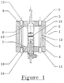
- FIGURE 1 is a vertical cross section through an assembly having two IR heat lamps, a bi-elliptical reflector, a single heat sink and a single heat flow restricting element.
- FIGURE 2 a is a horizontal cross section through an assembly having one IR heat lamp and an elliptical reflector.
- FIGURE 2b is a horizontal cross section through an assembly having two IR heat lamps and a bi-elliptical reflector.
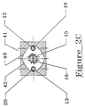
- FIGURE 2c is a horizontal cross section through an assembly having two IR heat lamps and two parabolic reflectors.
- FIGURE 2d is a horizontal cross-section through an assembly having four IR heat lamps and four parabolic reflectors.
- FIGURE 3 is a vertical cross section through the cooling assembly and the sensing assembly.
- FIGURE 4 is a vertical cross section through the sensing assembly showing the configuration of the differential thermal analysis sensor heat sink and heat flow restricting element.
- FIGURE 5 is a vertical cross section through an assembly having two IR heat lamps, a bi-elliptical reflector, two heat sinks and two heat flow restricting elements.
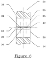
- FIGURE 6 is a vertical cross section through a sensing assembly with two heat flow restricting elements and two heat sinks, showing the configuration of the differential thermal analysis sensor and the heat flow restricting elements.
- Figure 1 is a vertical cross section of a first preferred embodiment through the plane of the lamp filaments of an IR heated DSC assembly which uses two IR heat lamps, a bi-elliptical reflector, a single heat sink and a single heat flow restricting element.
- the reflector assembly 1 includes reflector block 2 and end plates 3 and 4.
- Interior surface 5 of reflector block 2 is a bi-elliptical reflector which is polished to a mirror finish and then coated with gold, which is then also polished to a mirror finish. Gold is preferred over other reflective coatings because, in addition to possessing the requisite spectral reflectance, it does not tarnish.
- End plates 3 and 4 are flat. Their interior surfaces 6 and 7 are polished to a mirror finish.
- the surfaces are also coated with gold which is polished to a mirror finish. Holes 8, 9, 10 and 11, through the top and bottom end plates, allow the ends of IR heat lamps 12 and 13 to project through the end plates so that electrical connections (not shown) may be made to the lamps. This protects the vacuum seals of the lamps by allowing the ambient air to cool the seals.
- the reflectance of the gold coating in the IR region is less than 100%. Also, the IR lamps emit some radiation at wavelengths outside the range wherein the gold coating has a high reflectance. Because of these two factors, the block and the end plates are heated by absorption of IR radiation, thereby necessitating cooling the block and end plates. Furnace block 2 and end plates 3 and 4 are cooled, preferably by circulation of a coolant such as water through coolant passages (not shown) in the block and the end plates. Alternatively, the block and the end plates can be cooled by cooling fins on the exterior of the block and end plates.
- a coolant such as water
- coolant passages not shown
- Sensing assembly 16 and heat sink assembly 14 are enclosed by a quartz (vitreous silica) glass enclosure 15 which provides environmental isolation for the sensing assembly 16 and the sample material.
- Quartz glass is chosen for the enclosure because it has high broadband IR transmittance. IR radiation emitted by the lamps passes through the quartz enclosure tube with a very small absorptive loss. Furthermore, quartz can withstand sustained operation at temperatures as high as 1300 °C. It has a low thermal conductivity, reducing heat loss or gain by conduction of heat along the enclosure.
- the quartz enclosure allows the region surrounding the sensing assembly to be filled with a protective gas which prevents degradation of the sample during the experimental run, or it may be filled with a gas which reacts with the sample when such conditions are required.
- a protective gas which prevents degradation of the sample during the experimental run
- oxygen may be used to study the stability of samples under oxidizing conditions.
- An inlet and an outlet are provided to the enclosure so that the desired atmosphere may be introduced and maintained.
- Figure 2a is a cross sectional view of another embodiment of the present invention, which has a single elliptical reflector and a single IR heat lamp, taken transverse to the plane of the IR lamps (just above the plane of the heat flow sensor).
- the reflecting surface of reflector block 5 is the elliptical cross section cavity 18.
- Filament 20 of IR lamp 13 is located at one focus of the elliptical reflector cavity 18 and heat flow sensing assembly 16 is located at the other focus of the elliptical reflector. This configuration directs almost all the IR energy emitted by lamp filament 20 onto the surface of the sensing assembly 16, through quartz enclosure 15.
- Figure 2b is a cross sectional view of the first preferred embodiment, which has a bi-elliptical reflector, taken transverse to the plane of the IR lamps (just above the plane of the heat flow sensor).
- Bi-elliptical reflector surface 5 of the reflector block consists of two intersecting elliptical cavities 17 and 18, oriented such that the major axes of the ellipses are collinear, and such that one focus of each ellipse coincides with one focus of the other ellipse.
- the line defining the coincident foci is the axial centerline for the sensing assembly 16 and the quartz glass enclosure 15.
- Filament 19 of IR lamp 12 is located at one focus of elliptical reflector cavity 17, while filament 20 of the IR lamp 13 is located at one focus of elliptical reflector cavity 18.
- IR radiation passes through quartz glass enclosure 15, and heats sensing assembly 16.
- Figure 2c is a cross sectional view of another embodiment of the present invention, which has two parabolic reflectors and two heat lamps, taken transverse to the plane of the IR lamps (just above the plane of the heat flow sensor).
- Reflector block 41 includes the parabolic reflector surfaces 42 and 43. The reflectors are arranged so that their axes are collinear. Filament 19 of IR heat lamp 12 is located at the focus of the reflector 43, and filament 20 of IR heat lamp 13 is located at the focus of reflector 42.
- Heat flow sensing assembly 16 is positioned parallel to the lamp filaments along the reflector axes midway between the lamp filaments. This arrangement directs IR energy emitted from the heat lamps onto the surface of the heat flow sensing assembly, which heats the heat flow sensor assembly. Heat flow sensing assembly 16 is surrounded by quartz glass enclosure 15.
- Figure 2d is a cross sectional view of another embodiment of the present invention, which has four parabolic reflectors and four heat lamps, taken transverse to the plane of the IR lamps (just above the plane of the heat flow sensor).
- Reflector block 44 includes the parabolic reflector surfaces 45, 46, 47 and 48.
- the foci of the four parabolic reflectors are arranged in an equally spaced circular pattern about the centerline of the heat flow sensing assembly 16.
- the axes of the four parabolic reflectors intersect at the centerline of heat flow sensing assembly 16.
- the filaments 53, 54, 55, and 56 of the IR lamps 57, 58, 59, and 60 are located at the foci of the four parabolic reflectors. This configuration directs most of the infrared radiation emitted from the four lamps through the quartz enclosure 15 onto the surface of the heat flow sensing assembly 16, thereby heating the heat flow sensing assembly, the samples and the heat flow sensor.
- FIG. 3 is a vertical cross section through heat sink assembly 14 and sensing assembly 16 of the first preferred embodiment of the present invention, which has one heat flow restricting element and one heat sink.
- Heat sink 21 is a cylindrical metal bar with a closed end cooling passage 22. Tube 23 passes upward through the lower end of heat sink 21 into closed end cooling passage 22, terminating just below the end of the passage. Coolant for the heat sink enters the tube 23 via inlet 51, flows upward past the end of the tube and into passage 22, then flows downward inside cooling passage 22, absorbing heat from the heat sink and exiting at discharge tube 24 via coolant outlet 52.
- O-ring seal 25 in groove 26 at the lower end of the heat sink 21 contacts the inner surface of enclosure 15, sealing the enclosure to heat sink 21, and providing containment of the sample atmosphere.
- Heat flow sensing assembly 16 is surrounded by quartz glass enclosure 15.
- FIG 4 is an enlarged view of the vertical cross section through sensing assembly 16 shown in Figure 3.
- the upper end of the heat sink assembly 14 is joined to heat flow restricting element 28, which is joined to temperature equalizing ring 29, which in turn is joined to sensor assembly 30.
- Sensor assembly 30 is joined to another temperature equalizing ring 31, which is joined to upper sample region enclosure 32.
- a sample of the material to be analyzed is contained within sample pan 34, while reference pan 35 may be empty or may contain a (generally inert) reference material. All of the joints are made by brazing (or similar joining processes) to ensure complete and continuous joining of all components.
- Heat flow restricting element 28 is designed to provide a sufficient path for the flow of heat away from the sensor assembly 30, such that the desired cooling rates may be achieved, but also to have a limited heat conductance, such that the desired maximum temperature and heating rate can be achieved.
- the differential temperature across the heat flow restricting element can range from tens or hundreds of degrees Celsius, up to as much as 1,000 °C or more.
- the ideal material for heat flow restricting element 28 is a material with a relatively low thermal conductivity, so that its cross section and length are reasonable. Materials with relatively high thermal conductivity would have to have very thin walls and/or be very long to have sufficient thermal resistance. The material should also have relatively low heat capacity so that it does not store large quantities of heat. Because of the very large temperature difference which develops over its length, the heat flow restriction element will be subject to very high stresses due to differential thermal expansion. Generally this requires that the material be fairly ductile, i.e. , it will generally limit the material selection to metals. Radiation intercepted by the surface of the sensing assembly is generally not uniformly distributed. It may create an asymmetric temperature distribution in the sensor, which will cause extraneous heat flows during measurements. Such extraneous heat flows may result in deviation of the heat flow signal. These deviations of the baseline signal are highly undesirable.
- Temperature equalizing rings 29 and 31 serve to improve the uniformity of temperature about the circumference of the sensor assembly 30 by conduction of heat from higher temperature regions to lower temperature regions, thereby improving the symmetry of the temperature distribution within the sensor, resulting in a baseline heat flow which is very nearly zero over a wide range of temperatures.
- Temperature equalizing rings 29 and 31 are fabricated from a very high thermal conductivity material, so that heat flows readily in the rings to equalize any temperature non-uniformity. Silver, being the highest thermal conductivity metal, is the preferred material for the temperature equalizing rings when operating temperatures are below 725°C.
- the present invention can be used with both differential thermal analyzers and differential scanning calorimeters.
- the key distinguishing feature of a differential scanning calorimeter from a differential thermal analyzer is simply that the DSC has a baseline heat flow signal which differs very little from zero over a wide range of temperature and which is highly reproducible. This allows the temperature difference signal to be accurately calibrated to give heat flow.
- a symmetric temperature distribution in the sensor is an essential characteristic of a DSC.
- Lid 33 in Figure 4 covers the sample region. Its sole purpose is to prevent direct heating of the sample and reference pans by the IR radiation. Such extraneous heating would result in heat flow measurement errors.
- FIG. 5 is a vertical cross section of a second preferred embodiment of the present invention, which includes an IR heated DSC assembly which uses two heat lamps, a bi-elliptical reflector, two heat sinks and two heat flow restricting elements.
- the cross section is taken through the plane of the lamp filaments.
- the second embodiment is similar to the first embodiment, but includes a heat sink assembly 38 above the sensing assembly 36 as well as heat sink assembly 14 below it.
- Sensing assembly 36 and heat sink assemblies 14 and 38 are contained within a quartz (vitreous silica) glass enclosure 37 which provides environmental isolation for the sensing assembly 36 and hence for the sample material.
- upper heat sink assembly 38 is removed along with sample enclosure tube 37.
- the upper heat sink assembly 38 is essentially identical to the lower heat sink assembly and is joined to the upper heat flow restriction element.
- FIG. 6 is an enlarged view of the cross section through the sensing assembly shown in Figure 5.
- the differential thermal analysis sensor 30 is joined to lower temperature equalizing ring 29, which is joined to lower heat flow restricting element 28, which is joined to lower heat sink 14.
- Upper temperature equalizing ring 49 is joined to upper heat flow restricting element 39, which is joined to upper heat sink 38. All of the components are joined by brazing or by other similar joining methods.
- the assembly comprising upper temperature equalizing ring 49, upper heat flow restricting element 39 and upper heat sink 38 separates from the differential thermal analysis sensor 30 along the line 40, allowing access to the sample and reference holders for loading and unloading.
- Line 40 shows the interface between heat flow sensor 30 and upper temperature equalizing ring 49.
Landscapes
- Chemical & Material Sciences (AREA)
- Engineering & Computer Science (AREA)
- Chemical Kinetics & Catalysis (AREA)
- Combustion & Propulsion (AREA)
- Physics & Mathematics (AREA)
- Health & Medical Sciences (AREA)
- Life Sciences & Earth Sciences (AREA)
- Analytical Chemistry (AREA)
- Biochemistry (AREA)
- General Health & Medical Sciences (AREA)
- General Physics & Mathematics (AREA)
- Immunology (AREA)
- Pathology (AREA)
- Investigating Or Analyzing Materials Using Thermal Means (AREA)
Applications Claiming Priority (2)
| Application Number | Priority Date | Filing Date | Title |
|---|---|---|---|
| US171609 | 1993-12-21 | ||
| US08/171,609 US5509733A (en) | 1993-12-21 | 1993-12-21 | Infrared heated differential thermal analyzer |
Publications (2)
| Publication Number | Publication Date |
|---|---|
| EP0660110A1 true EP0660110A1 (de) | 1995-06-28 |
| EP0660110B1 EP0660110B1 (de) | 1999-06-02 |
Family
ID=22624442
Family Applications (1)
| Application Number | Title | Priority Date | Filing Date |
|---|---|---|---|
| EP94309170A Expired - Lifetime EP0660110B1 (de) | 1993-12-21 | 1994-12-08 | Durch Infrarotstrahlung beheiztes Differenzthermogerät |
Country Status (5)
| Country | Link |
|---|---|
| US (1) | US5509733A (de) |
| EP (1) | EP0660110B1 (de) |
| JP (2) | JPH07253405A (de) |
| CA (1) | CA2134432C (de) |
| DE (1) | DE69418839T2 (de) |
Cited By (6)
| Publication number | Priority date | Publication date | Assignee | Title |
|---|---|---|---|---|
| EP0887643A1 (de) * | 1997-06-24 | 1998-12-30 | LAR Analytik und Umweltmesstechnik GmbH | Verfahren zur Bestimmung eines Wasserinhaltsstoffes |
| EP1227317A2 (de) * | 2001-01-26 | 2002-07-31 | TA Instruments - Waters LLC | Thermisches Analysegerät mit verteiltem Widerstand und integriertem Flansch zur Befestigung von veschiedenen Kühlvorrichtungen |
| FR2917163A1 (fr) * | 2007-06-06 | 2008-12-12 | Waters Investments Ltd | Calorimetre a balayage differentiel a chauffage infrarouge |
| GB2478879A (en) * | 2007-06-06 | 2011-09-21 | Waters Technologies Corp | Thermal analysis using variable thermal resistance |
| WO2016188515A1 (de) * | 2015-05-22 | 2016-12-01 | Inoex Gmbh | Terahertz-messvorrichtung und verfahren zur vermessung von prüfobjekten mittels terahertz-strahlung |
| US20210190709A1 (en) * | 2017-11-06 | 2021-06-24 | Calbact Ag | Calorimeter and Sample Container for a Calorimeter |
Families Citing this family (20)
| Publication number | Priority date | Publication date | Assignee | Title |
|---|---|---|---|---|
| AU1685197A (en) * | 1995-12-08 | 1997-06-27 | University Of Alabama At Birmingham, The | Method and apparatus for cooling crystals |
| DE10156915B4 (de) * | 2001-11-21 | 2007-11-29 | Heraeus Noblelight Gmbh | Vorrichtung zum homogenen Erwärmen von Substraten oder Oberflächen und deren Verwendung |
| JP3760234B2 (ja) * | 2003-02-27 | 2006-03-29 | 独立行政法人産業技術総合研究所 | 双楕円柱面鏡を用いた対称x型光学系 |
| FR2878185B1 (fr) * | 2004-11-22 | 2008-11-07 | Sidel Sas | Procede de fabrication de recipients comprenant une etape de chauffe au moyen d'un faisceau de rayonnement electromagnetique coherent |
| US7425296B2 (en) | 2004-12-03 | 2008-09-16 | Pressco Technology Inc. | Method and system for wavelength specific thermal irradiation and treatment |
| US10857722B2 (en) * | 2004-12-03 | 2020-12-08 | Pressco Ip Llc | Method and system for laser-based, wavelength specific infrared irradiation treatment |
| US7416328B2 (en) * | 2004-12-28 | 2008-08-26 | Waters Investments Limited | System and method for a thermogravimetric analyzer having improved dynamic weight baseline |
| FR2913210B1 (fr) * | 2007-03-02 | 2009-05-29 | Sidel Participations | Perfectionnements a la chauffe des matieres plastiques par rayonnement infrarouge |
| US8087821B2 (en) * | 2007-06-06 | 2012-01-03 | Waters Technologies Corporation | Infrared heated differential scanning calorimeter |
| FR2917005B1 (fr) * | 2007-06-11 | 2009-08-28 | Sidel Participations | Installation de chauffage des corps de preformes pour le soufflage de recipients |
| CN101726373B (zh) * | 2009-12-30 | 2012-12-05 | 河南新天科技股份有限公司 | 一种红外方式智能热量表校准装置和方法 |
| US8564947B2 (en) * | 2010-02-12 | 2013-10-22 | Electronics And Telecommunications Research Institute | Heat exhaustion structure for heat dissipating device |
| DE102010008486B4 (de) * | 2010-02-18 | 2012-02-16 | Netzsch-Gerätebau GmbH | Temperiervorrichtung für thermoanalytische Untersuchungen |
| JP5709160B2 (ja) * | 2010-03-29 | 2015-04-30 | 株式会社日立ハイテクサイエンス | 熱分析装置 |
| CN102141529B (zh) * | 2010-12-30 | 2013-04-17 | 西安交通大学 | 一种固定结合面真空接触热导测量装置 |
| DE102013223945A1 (de) | 2013-11-22 | 2015-05-28 | Inoex Gmbh | Messvorrichtung und Verfahren zur Vermessung von Prüfobjekten |
| US9562845B2 (en) * | 2015-02-17 | 2017-02-07 | Xylem IP UK S. A R. L. | Technique for temperature controlling polarimeter sample cells |
| CN104777188A (zh) * | 2015-04-03 | 2015-07-15 | 中国纺织信息中心 | 一种远红外纺织品温升测试装置及测试方法 |
| KR102130872B1 (ko) * | 2016-04-27 | 2020-07-06 | 주식회사 엘지화학 | 고체 시료의 수분 측정 장치, 고체 시료 수분 함량 측정 방법 및 이미드화율 분석 방법 |
| WO2018096441A1 (en) * | 2016-11-22 | 2018-05-31 | Ta Instruments-Waters L.L.C. | Direct thermal injection thermal analysis |
Citations (4)
| Publication number | Priority date | Publication date | Assignee | Title |
|---|---|---|---|---|
| DE2704870A1 (de) * | 1977-02-05 | 1978-08-10 | Bayer Ag | Strahlungsbeheizter ofen |
| US4248083A (en) * | 1979-06-29 | 1981-02-03 | The United States Of America As Represented By The Administrator Of The National Aeronautics And Space Administration | Containerless high temperature calorimeter apparatus |
| JPS5923240A (ja) * | 1982-07-29 | 1984-02-06 | Agency Of Ind Science & Technol | 反応熱測定装置 |
| EP0498063A2 (de) * | 1991-01-04 | 1992-08-12 | The Perkin-Elmer Corporation | Schaltkreis zum Heizen und Fühlen der Temperatur mit einem einzelnen Widerstand |
Family Cites Families (10)
| Publication number | Priority date | Publication date | Assignee | Title |
|---|---|---|---|---|
| GB1074366A (en) * | 1965-03-10 | 1967-07-05 | Ici Ltd | Differential scanning calorimeter |
| US4126032A (en) * | 1976-03-23 | 1978-11-21 | Kabushiki Kaisha Daini Seikosha | Method and apparatus for determining photo-chemical reaction heat |
| DE2704871C3 (de) * | 1977-02-05 | 1981-03-26 | Bodenseewerk Perkin-Elmer & Co GmbH, 88662 Überlingen | Verfahren zu Differenzthermoanalyse |
| US4095453A (en) * | 1977-02-25 | 1978-06-20 | E. I. Du Pont De Nemours And Company | Differential thermal analysis cell |
| HU175262B (hu) * | 1977-04-14 | 1980-06-28 | Mta Mueszaki Fiz Kutato Inteze | Sposob i ustrojstvo termicheskogo analiza veshchestv |
| JPS57186147A (en) * | 1981-05-13 | 1982-11-16 | Agency Of Ind Science & Technol | Simultaneous measurement of heat quantity change and thermogravimetric change |
| US4567849A (en) * | 1981-12-01 | 1986-02-04 | Texas Instruments Incorporated | Dipping liquid phase epitaxy for HgCdTe |
| DE3511778A1 (de) * | 1985-03-30 | 1986-10-02 | Bayer Ag, 5090 Leverkusen | Verfahren und vorrichtung zur messung thermischer signale unter lichteinstrahlung |
| JPH0765974B2 (ja) * | 1988-10-26 | 1995-07-19 | セイコー電子工業株式会社 | 熱分析装置の加熱炉部冷却装置 |
| US5225766A (en) * | 1991-01-04 | 1993-07-06 | The Perkin Elmer Corporation | High impedance current source |
-
1993
- 1993-12-21 US US08/171,609 patent/US5509733A/en not_active Expired - Lifetime
-
1994
- 1994-10-26 CA CA002134432A patent/CA2134432C/en not_active Expired - Lifetime
- 1994-12-06 JP JP6301969A patent/JPH07253405A/ja active Pending
- 1994-12-08 DE DE69418839T patent/DE69418839T2/de not_active Expired - Lifetime
- 1994-12-08 EP EP94309170A patent/EP0660110B1/de not_active Expired - Lifetime
-
2000
- 2000-12-04 JP JP2000368630A patent/JP3338699B2/ja not_active Expired - Lifetime
Patent Citations (4)
| Publication number | Priority date | Publication date | Assignee | Title |
|---|---|---|---|---|
| DE2704870A1 (de) * | 1977-02-05 | 1978-08-10 | Bayer Ag | Strahlungsbeheizter ofen |
| US4248083A (en) * | 1979-06-29 | 1981-02-03 | The United States Of America As Represented By The Administrator Of The National Aeronautics And Space Administration | Containerless high temperature calorimeter apparatus |
| JPS5923240A (ja) * | 1982-07-29 | 1984-02-06 | Agency Of Ind Science & Technol | 反応熱測定装置 |
| EP0498063A2 (de) * | 1991-01-04 | 1992-08-12 | The Perkin-Elmer Corporation | Schaltkreis zum Heizen und Fühlen der Temperatur mit einem einzelnen Widerstand |
Non-Patent Citations (3)
| Title |
|---|
| A. DWORKIN: "COOLING DEVICE FOR LOW TEMPERATURE THERMAL ANALYSIS STUDIES", REVIEW OF SCIENTIFIC INSTRUMENTS, vol. 62, no. 6, June 1991 (1991-06-01), NEW-YORK, US, pages 1654 - 1655, XP000235665 * |
| C. BREMER: "A LASER TEMPERATURE JUMP APPARATUS BASED ON COMMERCIAL PARTS EQUIPPED WITH HIGHLY SENSITIVE SPECTROPHOTOMETRIC DETECTION", MEASUREMENT SCIENCE & TECHNOLOGY, vol. 4, no. 12, December 1993 (1993-12-01), BRISTOL, GB, pages 1385 - 1393, XP000424113 * |
| PATENT ABSTRACTS OF JAPAN vol. 8, no. 117 (P - 277)<1554> 31 May 1984 (1984-05-31) * |
Cited By (10)
| Publication number | Priority date | Publication date | Assignee | Title |
|---|---|---|---|---|
| EP0887643A1 (de) * | 1997-06-24 | 1998-12-30 | LAR Analytik und Umweltmesstechnik GmbH | Verfahren zur Bestimmung eines Wasserinhaltsstoffes |
| EP1227317A2 (de) * | 2001-01-26 | 2002-07-31 | TA Instruments - Waters LLC | Thermisches Analysegerät mit verteiltem Widerstand und integriertem Flansch zur Befestigung von veschiedenen Kühlvorrichtungen |
| EP1227317A3 (de) * | 2001-01-26 | 2004-02-04 | TA Instruments - Waters LLC | Thermisches Analysegerät mit verteiltem Widerstand und integriertem Flansch zur Befestigung von veschiedenen Kühlvorrichtungen |
| FR2917163A1 (fr) * | 2007-06-06 | 2008-12-12 | Waters Investments Ltd | Calorimetre a balayage differentiel a chauffage infrarouge |
| GB2478879A (en) * | 2007-06-06 | 2011-09-21 | Waters Technologies Corp | Thermal analysis using variable thermal resistance |
| GB2478879B (en) * | 2007-06-06 | 2011-11-16 | Waters Technologies Corp | System and method for thermal analysis using variable thermal resistance |
| DE112008001462B4 (de) * | 2007-06-06 | 2015-06-03 | Waters Technologies Corp. | Thermisches Messsystem und Verfahren zum Durchführen einer thermischen Analyse, wobei ein variabler thermischer Widerstand verwendet wird |
| WO2016188515A1 (de) * | 2015-05-22 | 2016-12-01 | Inoex Gmbh | Terahertz-messvorrichtung und verfahren zur vermessung von prüfobjekten mittels terahertz-strahlung |
| US20210190709A1 (en) * | 2017-11-06 | 2021-06-24 | Calbact Ag | Calorimeter and Sample Container for a Calorimeter |
| US11480534B2 (en) * | 2017-11-06 | 2022-10-25 | Calbact Ag | Calorimeter and sample container for a calorimeter |
Also Published As
| Publication number | Publication date |
|---|---|
| DE69418839T2 (de) | 1999-09-23 |
| US5509733A (en) | 1996-04-23 |
| JP3338699B2 (ja) | 2002-10-28 |
| DE69418839D1 (de) | 1999-07-08 |
| EP0660110B1 (de) | 1999-06-02 |
| JPH07253405A (ja) | 1995-10-03 |
| CA2134432A1 (en) | 1995-06-22 |
| CA2134432C (en) | 1998-11-17 |
| JP2001188053A (ja) | 2001-07-10 |
Similar Documents
| Publication | Publication Date | Title |
|---|---|---|
| EP0660110B1 (de) | Durch Infrarotstrahlung beheiztes Differenzthermogerät | |
| US20080304542A1 (en) | Infrared heated differential scanning calorimeter | |
| US7316969B2 (en) | Method and apparatus for thermally treating substrates | |
| US6310328B1 (en) | Rapid thermal processing chamber for processing multiple wafers | |
| US4857704A (en) | Apparatus for thermal treatments of thin parts such as silicon wafers | |
| US7130534B1 (en) | Gas chromatograph having a radiant oven for analytical devices | |
| GB2441833A (en) | Reaction Vessel | |
| JP3666831B2 (ja) | 熱分析及びx線測定装置 | |
| JPH06118039A (ja) | 熱分析装置 | |
| IE46449B1 (en) | Absorption spectrophotometry | |
| US20230160630A1 (en) | Refrigeration system | |
| US6084213A (en) | Method and apparatus for increasing temperature uniformity of heated wafers | |
| US10823650B2 (en) | Direct thermal injection thermal analysis | |
| JP6084961B2 (ja) | 多重反射容器 | |
| WO2008153910A1 (en) | Infrared heated differential scanning calorimeter | |
| JP6494543B2 (ja) | 多重反射セル | |
| US7559226B2 (en) | Radiant thermal energy absorbing analytical column | |
| Byrd et al. | Design, manufacture, and calibration of infrared radiometric blackbody sources | |
| JP3610855B2 (ja) | 分光光度計 | |
| JP2009236631A (ja) | 温度測定装置、これを有する載置台構造及び熱処理装置 | |
| JPH09126997A (ja) | 液体クロマトグラフ用光学式検出器 | |
| JPH0972669A (ja) | 空冷式超高温観察炉 | |
| JPH0921855A (ja) | 電子スピン共鳴用試料加熱方法および装置 | |
| JPS63149619A (ja) | 赤外線ランプ加熱による高温顕微鏡加熱装置 | |
| Bugby et al. | Experimental investigation of ROMPS coupled optical/thermal analysismethodology |
Legal Events
| Date | Code | Title | Description |
|---|---|---|---|
| PUAI | Public reference made under article 153(3) epc to a published international application that has entered the european phase |
Free format text: ORIGINAL CODE: 0009012 |
|
| AK | Designated contracting states |
Kind code of ref document: A1 Designated state(s): BE CH DE FR GB IT LI NL |
|
| 17P | Request for examination filed |
Effective date: 19950815 |
|
| 17Q | First examination report despatched |
Effective date: 19971118 |
|
| GRAG | Despatch of communication of intention to grant |
Free format text: ORIGINAL CODE: EPIDOS AGRA |
|
| GRAG | Despatch of communication of intention to grant |
Free format text: ORIGINAL CODE: EPIDOS AGRA |
|
| GRAH | Despatch of communication of intention to grant a patent |
Free format text: ORIGINAL CODE: EPIDOS IGRA |
|
| GRAH | Despatch of communication of intention to grant a patent |
Free format text: ORIGINAL CODE: EPIDOS IGRA |
|
| GRAA | (expected) grant |
Free format text: ORIGINAL CODE: 0009210 |
|
| AK | Designated contracting states |
Kind code of ref document: B1 Designated state(s): BE CH DE FR GB IT LI NL |
|
| PG25 | Lapsed in a contracting state [announced via postgrant information from national office to epo] |
Ref country code: NL Free format text: LAPSE BECAUSE OF FAILURE TO SUBMIT A TRANSLATION OF THE DESCRIPTION OR TO PAY THE FEE WITHIN THE PRESCRIBED TIME-LIMIT Effective date: 19990602 Ref country code: LI Free format text: LAPSE BECAUSE OF FAILURE TO SUBMIT A TRANSLATION OF THE DESCRIPTION OR TO PAY THE FEE WITHIN THE PRESCRIBED TIME-LIMIT Effective date: 19990602 Ref country code: IT Free format text: LAPSE BECAUSE OF FAILURE TO SUBMIT A TRANSLATION OF THE DESCRIPTION OR TO PAY THE FEE WITHIN THE PRESCRIBED TIME-LIMIT;WARNING: LAPSES OF ITALIAN PATENTS WITH EFFECTIVE DATE BEFORE 2007 MAY HAVE OCCURRED AT ANY TIME BEFORE 2007. THE CORRECT EFFECTIVE DATE MAY BE DIFFERENT FROM THE ONE RECORDED. Effective date: 19990602 Ref country code: CH Free format text: LAPSE BECAUSE OF FAILURE TO SUBMIT A TRANSLATION OF THE DESCRIPTION OR TO PAY THE FEE WITHIN THE PRESCRIBED TIME-LIMIT Effective date: 19990602 |
|
| REG | Reference to a national code |
Ref country code: CH Ref legal event code: EP |
|
| REF | Corresponds to: |
Ref document number: 69418839 Country of ref document: DE Date of ref document: 19990708 |
|
| ET | Fr: translation filed | ||
| REG | Reference to a national code |
Ref country code: CH Ref legal event code: PL |
|
| PLBE | No opposition filed within time limit |
Free format text: ORIGINAL CODE: 0009261 |
|
| STAA | Information on the status of an ep patent application or granted ep patent |
Free format text: STATUS: NO OPPOSITION FILED WITHIN TIME LIMIT |
|
| 26N | No opposition filed | ||
| REG | Reference to a national code |
Ref country code: GB Ref legal event code: IF02 |
|
| REG | Reference to a national code |
Ref country code: DE Ref legal event code: R082 Ref document number: 69418839 Country of ref document: DE Representative=s name: WEICKMANN & WEICKMANN, DE |
|
| REG | Reference to a national code |
Ref country code: GB Ref legal event code: 732E Free format text: REGISTERED BETWEEN 20131017 AND 20131023 |
|
| REG | Reference to a national code |
Ref country code: DE Ref legal event code: R082 Ref document number: 69418839 Country of ref document: DE Representative=s name: PATENTANWAELTE WEICKMANN & WEICKMANN, DE Effective date: 20130923 Ref country code: DE Ref legal event code: R082 Ref document number: 69418839 Country of ref document: DE Representative=s name: WEICKMANN & WEICKMANN, DE Effective date: 20130923 Ref country code: DE Ref legal event code: R081 Ref document number: 69418839 Country of ref document: DE Owner name: WATERS TECHNOLOGIES CORPORATION (N.D.GES.D. ST, US Free format text: FORMER OWNER: TA INSTRUMENTS, INC., NEW CASTLE, DEL., US Effective date: 20130923 Ref country code: DE Ref legal event code: R081 Ref document number: 69418839 Country of ref document: DE Owner name: WATERS TECHNOLOGIES CORPORATION (N.D.GES.D. ST, US Free format text: FORMER OWNER: TA INSTRUMENTS, INC., NEW CASTLE, US Effective date: 20130923 |
|
| REG | Reference to a national code |
Ref country code: FR Ref legal event code: TP Owner name: WATERS TECHNOLOGIES CORPORATION, US Effective date: 20131217 |
|
| PGFP | Annual fee paid to national office [announced via postgrant information from national office to epo] |
Ref country code: DE Payment date: 20131230 Year of fee payment: 20 Ref country code: GB Payment date: 20131227 Year of fee payment: 20 |
|
| PGFP | Annual fee paid to national office [announced via postgrant information from national office to epo] |
Ref country code: FR Payment date: 20131217 Year of fee payment: 20 |
|
| PGFP | Annual fee paid to national office [announced via postgrant information from national office to epo] |
Ref country code: BE Payment date: 20131227 Year of fee payment: 20 |
|
| REG | Reference to a national code |
Ref country code: DE Ref legal event code: R071 Ref document number: 69418839 Country of ref document: DE |
|
| REG | Reference to a national code |
Ref country code: GB Ref legal event code: PE20 Expiry date: 20141207 |
|
| PG25 | Lapsed in a contracting state [announced via postgrant information from national office to epo] |
Ref country code: GB Free format text: LAPSE BECAUSE OF EXPIRATION OF PROTECTION Effective date: 20141207 |