EP0659626A1 - Single running gear for rail vehicles - Google Patents
Single running gear for rail vehicles Download PDFInfo
- Publication number
- EP0659626A1 EP0659626A1 EP94118624A EP94118624A EP0659626A1 EP 0659626 A1 EP0659626 A1 EP 0659626A1 EP 94118624 A EP94118624 A EP 94118624A EP 94118624 A EP94118624 A EP 94118624A EP 0659626 A1 EP0659626 A1 EP 0659626A1
- Authority
- EP
- European Patent Office
- Prior art keywords
- running gear
- undercarriage
- chassis
- frame
- torsion bar
- Prior art date
- Legal status (The legal status is an assumption and is not a legal conclusion. Google has not performed a legal analysis and makes no representation as to the accuracy of the status listed.)
- Granted
Links
Images

Classifications
-
- B—PERFORMING OPERATIONS; TRANSPORTING
- B61—RAILWAYS
- B61F—RAIL VEHICLE SUSPENSIONS, e.g. UNDERFRAMES, BOGIES OR ARRANGEMENTS OF WHEEL AXLES; RAIL VEHICLES FOR USE ON TRACKS OF DIFFERENT WIDTH; PREVENTING DERAILING OF RAIL VEHICLES; WHEEL GUARDS, OBSTRUCTION REMOVERS OR THE LIKE FOR RAIL VEHICLES
- B61F5/00—Constructional details of bogies; Connections between bogies and vehicle underframes; Arrangements or devices for adjusting or allowing self-adjustment of wheel axles or bogies when rounding curves
- B61F5/02—Arrangements permitting limited transverse relative movements between vehicle underframe or bolster and bogie; Connections between underframes and bogies
- B61F5/22—Guiding of the vehicle underframes with respect to the bogies
- B61F5/24—Means for damping or minimising the canting, skewing, pitching, or plunging movements of the underframes
-
- F—MECHANICAL ENGINEERING; LIGHTING; HEATING; WEAPONS; BLASTING
- F02—COMBUSTION ENGINES; HOT-GAS OR COMBUSTION-PRODUCT ENGINE PLANTS
- F02B—INTERNAL-COMBUSTION PISTON ENGINES; COMBUSTION ENGINES IN GENERAL
- F02B3/00—Engines characterised by air compression and subsequent fuel addition
- F02B3/06—Engines characterised by air compression and subsequent fuel addition with compression ignition
Definitions
- the invention relates to a single undercarriage for rail vehicles, in particular for local and regional trains, according to the preamble of patent claim 1.
- EP 00 82 043 B1 discloses a single wheel undercarriage for rail vehicles, the wheelset bearings of which, via inclined rubber layer springs as the primary spring stage, accommodate the undercarriage frame with its cranked longitudinal members.
- the second spring stage is designed with four coil or rubber layer springs on the longitudinal beam ends. Trailing arms are provided for the articulation of the trolleys, which are attached to the base frame of the car body, pointing forwards or towards the center.
- single-wheel set bogies with a primary suspension between the wheelset mounting and the chassis frame and, with a secondary suspension towards the car body, which is formed by an inclined rubber layer spring arranged on the longitudinal beam ends and thus supports the car body on the driving or running gear.
- sliding surfaces can also be present on these secondary rubber layer springs, which are radial and to the center point "wheel set - longitudinal center of car” are arranged obliquely to the vertical. These sliding surfaces are used for better radial adjustment of the wheel sets when driving through bends than the lateral deflection of the secondary rubber layer spring alone would allow (cf. also EP 00 82 043 B1).
- All these single wheel set bogies have in common that the vertical reaction forces generated from the driving or braking torque act on the base frame of the car body via the four supporting points of the second spring stage which are present in each case.
- the radial adjustment of the wheel sets in the bend is made possible by the fact that a radial deflection of the wheel set can take place by transverse thrust in the four elastic support points or pendulums between the body and the chassis. This deflection is positively influenced by lower counterforces in the undercarriages with the inclined sliding surfaces which are provided in addition to the rubber layer springs.
- the pivot point is designed as a pivot and is arranged on the cross member of the drive.
- the chassis swivels around the pivot arranged as a fixed pivot outside the center of the axle, which also serves as a fixed point for absorbing the reaction forces from the drive and braking torque.
- the chassis designed in this way uses only two secondary suspension elements arranged above the axle bearing.
- a single-wheel single running gear which is equipped with self-steering wheels that can always be adjusted tangentially even in the curves.
- Both wheels of the undercarriage can each be swiveled around a vertical axis and connected via a transverse tie rod.
- This solution has no pivot. As a result, a clear centering between the body and the chassis frame to ensure the transverse mobility of the single-wheel single chassis is not against what has a lasting effect on the running behavior.
- the wings of the two opposite sides of the vehicle are connected to each other via a torsion bar, which acts as a transverse stabilizer and thus causes the vehicle construction to tilt towards the inside of the curve.
- the invention specified in claim 1 is based on the problem of creating a generic single chassis that runs centered under the body.
- the position of the body over the middle of the Chassis while ensuring its full transverse mobility should be made possible.
- pitching movements of the undercarriage should be avoided both when the car body is deflected vertically and when the tensile and braking forces are transmitted.
- the compensation device can advantageously be formed from a pendulum arrangement consisting of staggered links with a coupling element serving as a torsion bar.
- the pendulum arrangement can consist of rods or of pneumatic, electrical or hydraulic adjusting cylinders, wherein the coupling of the two subsystems can be solved via pneumatic, hydraulic, electrical or other force-transmitting elements.
- the centering device is formed from a rotary cradle, which is guided over diagonally arranged handlebars of equal length, the reception of the handlebar ends via corresponding bearings (with non-reactive characteristics - claim 8 -) and on the rotary cradle itself and the cross members of the chassis frame accordingly arranged consoles takes place.
- the single chassis is designed as a wheelset.
- the car body 1 is supported on the chassis frame 2 by means of a secondary suspension 5, which in the exemplary embodiment is formed from an air suspension, above the wheel set 3.
- the wheelset 3 is supported in the undercarriage frame 2 formed from the longitudinal beams 2a, the straight crossbeams 2b via the primary spring 4, which is preferably stiff in the longitudinal direction.
- the compensation device K which is arranged in the region of the longitudinal center axis FML of the chassis frame 2 , is composed of a pendulum arrangement 6 formed from links 6a and 6b, and of a torsion bar 7 formed coupling element, formed on the cross beams 2b and rigidly connected to the torsion bar 7, U-shaped receiving means 8 and 9, which receive the bearings 10 arranged at the ends of the links 6a and 6b.
- the bearings 10 have a non-reactive characteristic.
- the open sides of the U-shaped receiving devices 8 and 9 for the bearings 10 are in the rest position offset by 90 ° to one another on a perpendicular perpendicular MS.
- this solution prevents additional loading and unloading of the secondary suspension 5 as a result of reaction forces from the transmission of tensile and braking forces, which occurs, for example, in the case of a torsion bar arranged on one side.
- the centering device Z is formed from a rotary cradle 13 guided via links 12a and 12b.
- the pivoting cradle 13 is guided elastically via the diagonally opposite links 12a and 12b via brackets 15a and 15b to the crossbeams 2b of the chassis frame 2 , the two ends of the pivoting cradle 13 pointing to a defined area of the crossbeams 2b, where u-shaped ones Consoles 16a and 16b are arranged.
- Linkage axles 17 and 18, which are offset by 90 o from one another, serve to accommodate the bearings 11 of the links 12a and 12b.
Abstract
Description
Die Erfindung bezieht sich auf ein Einzelfahrwerk für Schienenfahrzeuge, insbesondere für Nah- und Regionalverkehrsbahnen nach dem Oberbegriff des Patentanspruchs 1.The invention relates to a single undercarriage for rail vehicles, in particular for local and regional trains, according to the preamble of patent claim 1.
Einzelfahrwerke, ausgebildet als Radsatz- oder Einzelradfahrwerk, werden bei leichten zweiachsigen Schienenfahrzeugen, wie zum Beispiel Dieseltriebwagen, angewendet. Sie werden durch ihre Anlenkungen zum Wagenkastengrundrahmen hin in ihrem Laufverhalten und im Verschleiß der Spurkränze und der Laufflächen der Räder beeinflußt.Single trolleys, designed as wheelset or single wheel trolleys, are used in light two-axle rail vehicles, such as diesel railcars. They are influenced by their articulations towards the body frame in their running behavior and in the wear of the wheel flanges and the running surfaces of the wheels.
Alle bekannten Lösungen erfüllen die Aufgabe der Übertragung der Zug- und Bremskräfte. Das führt aber bei allen Konstruktionen zu einer zusätzlichen, zug- bzw. bremskraftabhängigen Be- oder Entlastung der Sekundärfedern. Weiterhin ist bei allen Lösungen, die mit einem ideellen Drehzapfen arbeiten, dieser nicht in allen kinematischen Zuständen des Fahrwerkes wirklich über der Mitte der Radachse geführt wird. Dies führt bei Bogenfahrt zu einer der Wendebewegung überlagerten Gleitbewegung und somit zum Verschleiß des Radsatzes.All known solutions fulfill the task of transmitting the tensile and braking forces. In all constructions, however, this leads to an additional load or relief of the secondary springs that is dependent on traction or braking force. Furthermore, in all solutions that work with an ideal pivot, this is not really guided over the center of the wheel axis in all kinematic states of the chassis. This leads to a sliding movement superimposed on the turning movement and thus to wear of the wheel set when traveling through bends.
Aus der EP 00 82 043 B1 ist ein Einzelradfahrwerk für Schienenfahrzeuge bekannt, dessen Radsatzlager über schräggestellte Gummischichtfedern als Primärfederstufe den Fahrwerksrahmen mit seinen gekröpft ausgeführten Längsträgern aufnehmen. Die zweite Federstufe ist mit vier Schrauben- oder Gummischichtfedern an den Längsträgerenden ausgeführt. Zur Anlenkung der Fahrwerke sind Längslenker vorgesehen, die am Wagenkastengrundrahmen nach vorn oder zur Mitte weisend befestigt sind.EP 00 82 043 B1 discloses a single wheel undercarriage for rail vehicles, the wheelset bearings of which, via inclined rubber layer springs as the primary spring stage, accommodate the undercarriage frame with its cranked longitudinal members. The second spring stage is designed with four coil or rubber layer springs on the longitudinal beam ends. Trailing arms are provided for the articulation of the trolleys, which are attached to the base frame of the car body, pointing forwards or towards the center.
Bekannt sind weiterhin Einzelradsatzfahrwerke mit einer Primärfederung zwischen Radsatzlagerung und Fahrwerksrahmen und, mit einer Sekundärfederung zum Wagenkasten hin, die durch je eine an den Längsträgerenden angeordnete schräggestellte Gummischichtfeder gebildet wird und somit den Wagenkasten auf dem Fahr- oder Laufwerk abstützt. Zusätzlich können an diesen Sekundär-Gummischichtfedern noch Gleitflächen vorhanden sein, die zum Mittelpunkt "Radsatz - Wagenlängsmitte", radial und schräg zur Vertikalen, angeordnet sind. Diese Gleitflächen dienen zur besseren Radialeinstellung der Radsätze bei Bogendurchfahrten als sie die seitliche Auslenkung der Sekundär-Gummischichtfeder allein zulassen würde (vgl. hierzu ebenfalls die EP 00 82 043 B1).Also known are single-wheel set bogies with a primary suspension between the wheelset mounting and the chassis frame and, with a secondary suspension towards the car body, which is formed by an inclined rubber layer spring arranged on the longitudinal beam ends and thus supports the car body on the driving or running gear. In addition, sliding surfaces can also be present on these secondary rubber layer springs, which are radial and to the center point "wheel set - longitudinal center of car" are arranged obliquely to the vertical. These sliding surfaces are used for better radial adjustment of the wheel sets when driving through bends than the lateral deflection of the secondary rubber layer spring alone would allow (cf. also EP 00 82 043 B1).
Weiterhin ist die Lösung eines Einzelradsatz-Triebfahrwerkes für einen Diesel-Kleintriebwagen bekannt, an dessen vier Fahrwerksrahmenlängsträgerenden Pendel vorhanden sind, die über Gummischichtfedern als zweite Federstufe den Wagenkasten abstützen. Die Längskräfte durch die Antriebs- bzw. Bremskräfte werden vom Fahrwerksrahmen mittels Längslenkern auf den Wagenkastengrundrahmen übertragen. Die beiden Längslenker verbinden einen Querbalken mit dem Grundrahmen. Der Querbalken ist wiederum über einen Drehpunkt am Querträger des Fahrwerkes befestigt. Der Radsatz wird dabei wie an einer Deichsel gezogen oder geschoben. Die Querauslenkung wird durch die Rückstellkraft der Pendel bestimmt. (Vgl. dazu eine Werksinformation der CESKOSLOVENSKE VAGONKY G.R., PRAHA, RAIL 76, Dieseltriebwagen M152 in der CSSR, Abb. 11).Furthermore, the solution of a single-wheel drive unit for a small diesel locomotive is known, on the four chassis frame longitudinal beam ends of which there are pendulums that support the car body as rubber springs as a second spring step. The longitudinal forces from the drive or braking forces are transmitted from the chassis frame to the basic body of the car body by means of trailing arms. The two trailing arms connect a crossbeam to the base frame. The crossbar is in turn attached to the crossmember of the undercarriage via a pivot point. The wheelset is pulled or pushed like a drawbar. The transverse deflection is determined by the return force of the pendulum. (See also a works information from CESKOSLOVENSKE VAGONKY G.R., PRAHA, RAIL 76, diesel railcar M152 in the CSSR, Fig. 11).
Alle diese Einzelradsatzfahrwerke haben gemeinsam, daß die aus dem Antriebs- bzw. Bremsmoment erzeugten vertikalen Reaktionskräfte über die jeweils vorhandenen vier Abstützpunkte der zweiten Federstufe auf den Wagenkastengrundrahmen wirken. Die radiale Einstellung der Radsätze im Bogen wird dadurch ermöglicht, daß durch Querschub in den vier elastischen Abstützpunkten bzw. Pendeln zwischen Wagenkasten und Fahrwerk ein radiales Auslenken des Radsatzes erfolgen kann. Diese Auslenkung wird bei den Fahrwerken mit den zusätzlich zu den Gummischichtfedern vorhandenen schräggestellten Gleitflächen durch geringere Gegenkräfte positiv beeinflußt.All these single wheel set bogies have in common that the vertical reaction forces generated from the driving or braking torque act on the base frame of the car body via the four supporting points of the second spring stage which are present in each case. The radial adjustment of the wheel sets in the bend is made possible by the fact that a radial deflection of the wheel set can take place by transverse thrust in the four elastic support points or pendulums between the body and the chassis. This deflection is positively influenced by lower counterforces in the undercarriages with the inclined sliding surfaces which are provided in addition to the rubber layer springs.
Als nachteilig bei diesen Lösungen ist die komplizierte Bauweise anzusehen, die mit einem hohen technologischen Herstellungsaufwand verbunden ist. Auf Grund der als ungenügend angesehenen radialen Einstellung der Radachsen bei Bogendurchlauf ergibt sich ein relativ hoher Spurkranzverschleiß.A disadvantage of these solutions is the complicated construction, which is associated with a high level of technological production. Due to the inadequate radial setting of the wheel axles when passing through bends, there is a relatively high wear on the flange.
Weiterhin ist aus der Zeitschrift Verkehr und Technik 2/56 (9. Jahrgang), Seite 56 bis 59, "Diesel-Leichttriebwagen mit Einachsdeichselgestellen", insbesondere Bild 5, ein an einer Deichsel geführtes Einzelradsatzfahrwerk bekannt, dessen Anlenkpunkt als Drehzapfen ausgebildet ist und am Querträger des Laufwerkes angeordnet ist. Das Fahrwerk vollzieht bei Fahrt eine Schwenkung um den als festen Drehpunkt außerhalb des Achsmittelpunktes angeordneten Drehzapfen, der gleichzeitig als Festpunkt für die Aufnahme der Reaktionskräfte aus dem Antriebs- und Bremsmoment dient. Das derart ausgebildete Fahrwerk verwendet dabei nur zwei über dem Achslager angeordnete Sekundärfederungselemente.Furthermore, from the magazine Verkehr und Technik 2/56 (9th year), pages 56 to 59, "Diesel light rail cars with single-axle drawbar frames", in particular Fig. 5, a single wheel set running gear on a drawbar known, the pivot point is designed as a pivot and is arranged on the cross member of the drive. When traveling, the chassis swivels around the pivot arranged as a fixed pivot outside the center of the axle, which also serves as a fixed point for absorbing the reaction forces from the drive and braking torque. The chassis designed in this way uses only two secondary suspension elements arranged above the axle bearing.
Nachteilig bei derart ausgeführten Einzelradsatzfahrwerken ist das negative Verschleißverhalten der Radsätze bei Bogendurchfahrten. Die Ursache für das Auftreten hoher Verschleißwerte ist in dem außerhalb des Achsmittelpunktes angeordneten Drehzapfen zu sehen.A disadvantage of such individual wheel set undercarriages is the negative wear behavior of the wheel sets when driving through bends. The cause of the occurrence of high wear values can be seen in the pivot located outside the center of the axis.
Weiterhin ist ein Einzelrad-Einzelfahrwerk bekannt, das mit selbststeuernden, auch in den Kurven immer tangential einstellbaren Rädern ausgerüstet ist. (Vgl. die Zeitschrift "Elektrische Bahnen" 89/1991 Nr. 6, Seite 193 bis 196, "Die Straßenbahn-Niederflurfahrzeuge NGT 6 C Kassel", Pkt. 2 Wagenbaulicher Teil, insbesondere Bild 3). Beide Räder des Fahrwerkes sind jeweils um eine Hochachse schwenkbar und über eine querliegende Spurstange verbunden. Hierbei ist von Nachteil, daß diese Lösung keinen Drehzapfen aufweist. Dadurch ist eine eindeutige Zentrierung zwischen Wagenkasten und Fahrwerksrahmen, zur Gewährleistung der Querbeweglichkeit des Einzelrad-Einzelfahrwerkes, nicht gegen, was sich nachhaltig auf das Laufverhalten auswirkt.Furthermore, a single-wheel single running gear is known, which is equipped with self-steering wheels that can always be adjusted tangentially even in the curves. (See the magazine "electric railways" 89/1991 No. 6, pages 193 to 196, "the tram low-floor vehicles NGT 6 C Kassel",
Auch sind Lösungen zur Wankstabilisierung des Wagenkastens von Fahrzeugen bekannt,
- die einen in Fahrzeugquerrichtung liegenden Querstabilisator, wie einen Torsionsstab anwenden (DE 28 41 769 A1),
- die eine zwischen dem Wagenkasten und dem Drehgestellrahmen angeordnete Wankstütze verwenden (DE 35 10 454 A1),
- die über ein Federmedium und eine Druckänderung entsprechende Längenänderungen auswerten und kompensieren (DE-AS 11 76 693, DE 39 42 654 A1, DE 38 21 609 A1), wobei entsprechende Regelmaßnahmen sowohl hydraulisch (DE 38 21 610 A1) als auch mittels einer elektronischen Regeleinrichtung (DE 39 07 870 C2) durchführbar sind.
- who use a transverse stabilizer lying in the transverse direction of the vehicle, such as a torsion bar (DE 28 41 769 A1),
- who use a roll support arranged between the car body and the bogie frame (DE 35 10 454 A1),
- evaluate and compensate for the corresponding changes in length via a spring medium and a pressure change (DE-AS 11 76 693, DE 39 42 654 A1, DE 38 21 609 A1), appropriate control measures being both hydraulic (DE 38 21 610 A1) and by means of an electronic control device (DE 39 07 870 C2) can be carried out.
Diese Lösungen sind jedoch in ihrer Gesamtheit nicht einsetzbar, um eine Lösung zu realisieren, die ein Stabilisieren eines Schienenfahrzeug-Einzelfahrwerkes hinsichtlich auftretender Nickbewegungen und seiner Querstabilität selbst gewährleistet.However, these solutions cannot be used in their entirety to implement a solution that guarantees the stabilization of a single rail vehicle chassis with regard to pitching movements and its transverse stability itself.
Die DE 28 41 769 A1 zeigt die Lösung an einem zweiachsigen Drehgestell, bei der die Fahrzeugachsen des Drehgestells um eine Schwenkachse schwenkbar (relativ zur Fahrzeuglängsachse) gelagert sind, aber im übrigen fest zum Fahrzeugaufbau gehalten werden . Beim Durchfahren einer Kurve verschwenkt sich das Drehgestell um einen bestimmten Winkel zur Fahrzeuglängsachse über ein Drehkranzsegment. Entsprechende auf dem Drehgestell links und rechts angeordnete Schraubenfedern stützen den Fahrzeugaufbau ab, wobei das untere und obere Federlager vertikalbeweglich an einem Schwingenhalter am Drehgestell selbst befestigt sind. Auf der Oberseite der Schwinge befindet sich ein Gleitschuh, der mit der Gleitfläche des Drehkranzes zusammen arbeitet. Die Schwingen der beiden gegenüberliegenden Fahrzeugseiten sind dabei untereinander über einen Torsionsstab miteinander verbunden, der als Querstabilisator wirkt und somit eine Querneigung des Fahrzeugbaues zum Kurveninneren herbeiführt. Damit wird zwar eine Wankbewegung des Schienenfahrzeug-Wagenkastens selbst bei radialer Einstellung der Radsätze ausgeglichen, eine Nickbewegung des Fahrwerkes aber nicht vermieden, was zu einer Verspannung des Fahrwerkes selbst führen kann (was bei Bogenfahrt zu erhöhtem Radreifenverschleiß führt).DE 28 41 769 A1 shows the solution on a biaxial bogie, in which the vehicle axles of the bogie are pivotable about a pivot axis (relative to the longitudinal axis of the vehicle), but are otherwise held firmly to the vehicle body. When driving through a curve, the bogie swivels through a certain angle to the vehicle's longitudinal axis via a slewing ring segment. Corresponding coil springs arranged on the left and right of the bogie support the vehicle body, the lower and upper spring bearings being fastened vertically to a rocker bracket on the bogie itself. On the top of the swing arm there is a sliding block that works together with the sliding surface of the slewing ring. The wings of the two opposite sides of the vehicle are connected to each other via a torsion bar, which acts as a transverse stabilizer and thus causes the vehicle construction to tilt towards the inside of the curve. This compensates for a rolling movement of the rail vehicle body, even with the wheelsets set radially, but does not prevent pitching of the undercarriage, which can lead to tension in the undercarriage itself (which leads to increased tire wear when traveling on bends).
Lösungen zur Vermeidung der Nickbewegungen sind bei Straßenfahrzeugen allgemein bekannt (sh. dazu DE 33 35 861 A1 und DE 39 37 674 A1), die sowohl entsprechende hydraulische Komponenten als auch mechanische Stellglieder (Torsionsstab) verwenden, aber in der Form und Anordnung bei Einzelfahrwerken für Schienenfahrzeuge nicht anwendbar sind.Solutions for avoiding pitching movements are generally known in road vehicles (see also DE 33 35 861 A1 and DE 39 37 674 A1), which use corresponding hydraulic components as well as mechanical actuators (torsion bar), but in the form and arrangement of individual running gear for Rail vehicles are not applicable.
Der im Anspruch 1 angegebenen Erfindung liegt das Problem zugrunde, ein gattungsgemäßes Einzelfahrwerk zu schaffen, das zentriert unter dem Wagenkasten läuft. Die Haltung des Wagenkastens über der Mitte des Fahrwerkes bei Gewährleistung seiner vollen Querbeweglichkeit soll ermöglicht werden. Gleichzeitig sollen Nickbewegungen des Fahrwerkes sowohl beim vertikalen Einfedern des Wagenkastens als auch beim Übertragen der Zug- und Bremskräfte vermieden werden.The invention specified in claim 1 is based on the problem of creating a generic single chassis that runs centered under the body. The position of the body over the middle of the Chassis while ensuring its full transverse mobility should be made possible. At the same time, pitching movements of the undercarriage should be avoided both when the car body is deflected vertically and when the tensile and braking forces are transmitted.
Dieses Problem wird erfindungsgemäß mit den Merkmalen des Anspruches 1 gelöst. Vorteilhafte Ausgestaltungen der Erfindung sind in den Ansprüchen 2 bis 8 angegeben.This problem is solved according to the invention with the features of claim 1. Advantageous embodiments of the invention are specified in
Gemäß Anspruch 2 kann die Kompensationseinrichtung vorteilhafterweise aus einer aus versetzt angeordneten Lenkern bestehenden Pendelanordnung mit einem als Torsionsstab dienenden Koppelelement gebildet werden.According to
In weiterer Ausbildung der Erfindung kann gemäß Anspruch 3 die Pendelanordnung aus Stäben oder aus pneumatischen, elektrischen oder hydraulischen Verstellzylindern bestehen, wobei die Kopplung der beiden Teilsysteme über pneumatische, hydraulische, elektrische oder über andere Kräfte übertragende Elemente gelöst werden kann.In a further embodiment of the invention, the pendulum arrangement can consist of rods or of pneumatic, electrical or hydraulic adjusting cylinders, wherein the coupling of the two subsystems can be solved via pneumatic, hydraulic, electrical or other force-transmitting elements.
Gemäß Anspruch 4 wird die Zentriereinrichtung aus einer Drehwiege gebildet, die über diagonal angeordnete gleich lange Lenker geführt ist, wobei die Aufnahme der Lenkerenden über entsprechende Lager (mit rückwirkungsfreier Charakteristik - Anspruch 8 -) und an der Drehwiege selbst und den Querträgern des Fahrwerkrahmens über entsprechend angeordnete Konsolen erfolgt.According to
In weiterer Ausbildung der Lösung kann nach Anspruch 5 zur Bildung des Drehpunktes Drehgestell/Wagenkasten ein Kugeldrehkranz Anwendung finden.In a further embodiment of the solution, a ball slewing ring can be used according to
Bei Anwendung eines als Koppelelement dienenden Torsionsstabes kann dieser vorteilhaft gemäß Anspruch 6 drehbar gelagert am Wagenkasten geführt sein. Andererseits besteht nach Anspruch 7 die Möglichkeit, den als Kopplungselement eingesetzten Torsionsstab horizontal drehbar im Fahrwerksrahmen selbst zu lagern und die Lenker dabei gelenkig mit dem Wagenkasten in Verbindung zu bringen.When using a torsion bar serving as a coupling element, it can advantageously be rotatably mounted on the body according to
Die mit der Erfindung erzielten Vorteile bestehen insbesondere darin, daß ein als Radsatz oder Einzelradfahrwerk ausgebildetes Einzelfahrwerk in der Lage ist, sich durch Wenden ohne ein Quergleiten radial einstellen kann und wirkungsvoll am Nicken gehindert wird. Die Übertragung der Zug- und Bremskräfte erfolgt ohne nachteilige Rückwirkungen auf das Fahrwerk und den Wagenkasten. Ein zunächst prinzipiell instabiles System wird mit relativ geringem technologischen Aufwand hinematisch eindeutig stabilisiert.The advantages achieved by the invention are, in particular, that a single running gear designed as a wheel set or single wheel running gear is able to adjust itself radially by turning without transverse sliding and is effectively prevented from pitching. The transmission of the traction and braking forces takes place without adverse effects on the chassis and the body. A system that is initially unstable is unambiguously stabilized with relatively little technological effort.
Ein Ausführungsbeispiel der Erfindung soll anhand der Zeichnung gemäß den Fig. 1 bis 4 näher erläutert werden.An embodiment of the invention will be explained in more detail with reference to the drawing according to FIGS. 1 to 4.
Es zeigen:
- Fig. 1:
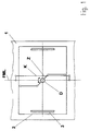
- das Prinzip der Kombination einer Kompensations- und einer Zentriereinrichtung einerseits zur Aufnahme der gegenläufigen vertikalen Bewegungen der äußeren Fahrwerks-Querträger zur Vermeidung des Nickens und andererseits zur Gewährleistung der Querbeweglichkeit des Einzelfahrwerkes selbst;
- Fig. 2:
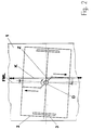
- das Prinzip nach Fig. 1 mit angedeuteten Ausgleichbewegungen und Kräftefluß bei Kurvenfahrt;
- Fig. 3:
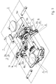
- die Gesamtansicht eines als Einzelfahrwerk ausgebildeten Radsatzlaufwerkes mit der konstruktiven Lage einer aus Lenkern und einem Torsionsstab gebildeten Kompensationseinrichtung und einer aus einer Drehwiege gebildeten Zentriereinrichtung;
- Fig. 4:
- die konkrete Ausführung der Kompensationseinrichtung und Zentriereinrichtung als Baugruppe gemäß Fig. 3.
- Fig. 1:
- the principle of the combination of a compensation and a centering device on the one hand to accommodate the opposite vertical movements of the outer chassis cross member to avoid pitching and on the other hand to ensure the transverse mobility of the individual chassis itself;
- Fig. 2:
- the principle of Figure 1 with indicated compensatory movements and flow of forces when cornering.
- Fig. 3:
- the overall view of a wheel set designed as a single carriage with the structural position of a compensation device formed from handlebars and a torsion bar and a centering device formed from a rotary cradle;
- Fig. 4:
- the concrete design of the compensation device and centering device as an assembly according to FIG. 3.
Die gemäß Fig. 1 aufgezeigte Lösung zeigt die prinzipielle Anbindung eines aus einem Fahrwerkrahmen 2 und einem Radsatz 3 gebildeten Einzelfahrwerkes an den Wagenkasten 1 eines Schienenfahrzeuges in Ruhestellung. Die wesentlichen Baugruppen, die die Funktionen
- a) Übertragung der Zug- und Bremskräfte,
- b) Zentrierung des Fahrwerkes unter dem Wagenkasten über der Radsatzmitte und
- c) Stabilisierung des Fahrwerkes und Nickbewegungen des Fahrwerks verhindern
- a) transmission of tensile and braking forces,
- b) centering the undercarriage under the body over the center of the wheelset and
- c) Prevent stabilization of the undercarriage and pitching movements of the undercarriage
Fig. 2 zeigt dabei die auftretenden Kräfte und Bewegungen beider Einrichtungen für einen bestimmten Fall (hierbei Kurvenfahrt rechts und angenommene übliche Nickbewegung zur Schiene des Fahrwerkrahmen-Querträgers 2b bei Lösungen nach dem Stand der Technik).2 shows the forces and movements occurring for both devices for a specific case (here cornering to the right and assumed usual pitching movement to the rail of the chassis
Durch die symmetrische Erfassung und Kompensation der auftretenden Kräfte aus Nickbewegungen des Fahrwerkes ist es möglich, von vorn herein Verspannungen im Fahrwerk selbst zu vermeiden. Die symmetrische beidseitige Anbindung der Drehwiege an den Fahrwerkrahmen, wobei die Anbindungselemente (Lager ect.) ebenfalls eine rückwirkungsfreie Charakteristik aufweisen müssen, gestatten es, auftretende Kräfte aus den Quer- und Vertikalbewegungen zwischen Fahrwerk und Wagenkasten ebenfalls zu kompensieren, so daß hieraus ebenfalls keine Verspannungen im Fahrwerk auftreten können.The symmetrical detection and compensation of the forces arising from pitching movements of the undercarriage make it possible to avoid tension in the undercarriage itself from the outset. The symmetrical connection of the rotary cradle to the chassis frame on both sides, whereby the connection elements (bearings etc.) must also have a non-reactive characteristic, also allow forces arising from the transverse and vertical movements between the chassis and the body to be compensated, so that there is also no tension can occur in the chassis.
Gemäß Fig. 3 und 4 ist das Einzelfahrwerk als Radsatzlaufwerk ausgebildet. Der Wagenkasten 1 ist auf dem Fahrwerkrahmen 2 mittels einer Sekundärfederung 5, die im Ausführungsbeispiel aus einer Luftfederung gebildet wird, oberhalb des Radsatzes 3 abgestützt. Der Radsatz 3 wird in dem aus den Längsträgern 2a, den geraden Querträgern 2b gebildeten Fahrwerkrahmen 2 über die Primärfeder 4 gelagert, die in Längsrichtung vorzugsweise steif ausgebildet ist.3 and 4, the single chassis is designed as a wheelset. The car body 1 is supported on the
Die Kompensationseinrichtung K, im Bereich der Fahrwerksmittenlängsachse FML des Fahrwerkrahmens 2 angeordnet, wird dabei aus einer aus Lenkern 6a und 6b gebildeten Pendelanordnung 6, aus einem als Torsionsstab 7 ausgebildetem Kopplungselement, an den Querträgern 2b und mit dem Torsionsstab 7 starr verbundenen, u-förmig ausgebildeten Aufnahmeeinrichtungen 8 und 9, die die an den Enden der Lenker 6a und 6b angeordneten Lager 10 aufnehmen, gebildet. Die Lager 10 weisen dabei eine rückwirkungsfreie Charakteristik auf. Die offenen Seiten der u-förmigen Aufnahmeeinrichtungen 8 und 9 für die Lager 10 liegen dabei in Ruhestellung um 90o versetzt zueinander auf einer Mittelsenkrechten MS. Hierdurch wird das Fahrwerk einerseits stabilisiert (Dreipunktlagerung) und andererseits am Nicken gehindert (Verdrehen des Torsionsstabes 7). Weiterhin wird durch diese Lösung eine zusätzliche Be- und Entlastung der Sekundärfederung 5 infolge von Reaktionskräften aus der Übertragung von Zug- und Bremskräften, welche zum Beispiel bei einem einseitig angeordneten Torsionsstab auftritt, verhindert.The compensation device K, which is arranged in the region of the longitudinal center axis FML of the
Die Zentriereinrichtung Z wird aus einer über Lenker 12a und 12b geführten Drehwiege 13 gebildet. Die Führung der Drehwiege 13 erfolgt dabei elastisch über die diagonal gegenüberliegenden Lenker 12a und 12b über Konsole 15a und 15b zu den Querträgern 2b des Fahrwerkrahmens 2 hin, wobei die beiden Enden der Drehwiege 13 zu einem definierten Bereich der Querträger 2b weisen, wo u-förmige Konsolen 16a und 16b angeordnet sind. Zur Aufnahme der Lager 11 der Lenker 12a und 12b dienen Anlenkachsen 17 und 18, die um 90o zueinander versetzt liegen. Die Befestigung der Drehwiege 13 zum Wagenkasten 1 hin erfolgt über ein vertikal drehbares (um den Drehpunkt D Drehgestell/Wagenkasten) in ihr angeordnetes Radiallager 14. Durch diese Anordnung sind sowohl die Übertragung der Zug- und Bremskräfte als auch die Zentrierung des Einzelradsatzfahrwerkes selbst gegeben.The centering device Z is formed from a
- 1 -1 -
- WagenkastenCar body
- 2 - 2 -
- Fahrwerkrahmen gebildet ausLanding gear frame formed from
- 2a -2a -
- LängsträgerSide member
- 2b -2 B -
- Querträger (gerade)Cross member (straight)
- 3 -3 -
- RadsatzWheelset
- 4 -4 -
- PrimärfederungPrimary suspension
- 5 -5 -
- SekundärfederungSecondary suspension
- 6 - 6 -
- PendelanordnungPendulum arrangement
- 6a ) -6a) -
- Lenker der PendelanordnungHandlebar of the pendulum arrangement
- 6b ) -6b) -
- 7 -7 -
- Torsionsstab als KopplungselementTorsion bar as a coupling element
- 8 -8th -
- u-förmig ausgebildete, an den Querträgern angeordnete AufnahmeeinrichtungenU-shaped receiving devices arranged on the cross beams
- 9 -9 -
- u-förmig ausgebildete, am Torsionsstab angeordnete AufnahmeeinrichtungenU-shaped receiving devices arranged on the torsion bar
- 10 -10 -
- Lager ) mit rückwirkungsfreier CharakteristikBearings) with non-reactive characteristics
- 11 -11 -
- Lager)Camp)
- K -K -
- (Pos. 6 bis 10) Kompensationseinrichtung(Pos. 6 to 10) compensation device
- 12a - )12a -)
- LenkerHandlebars
- 12b - )12b -)
- 13 -13 -
- DrehwiegeRotary cradle
- 14 -14 -
- Radiallager der DrehwiegeRadial bearing of the rotary cradle
- 15a - )15a -)
- Konsoleconsole
- 15b - )15b -)
- 16a - )16a -)
- Konsoleconsole
- 16b - )16b -)
- 17 -17 -
-
Anlenkachsen der Lager 11Articulation axes of the
bearings 11 - Z -Z -
- Zentriereinrichung (Pos. 11 - 16b)Centering device (pos. 11 - 16b)
- MS -MS -
- MittelsenkrechtePerpendicular bisector
- FML -FML -
- FahrzeugmittenlängsachseCentral vehicle longitudinal axis
- D -D -
- Drehpunkt Drehgestell/WagenkastenPivot bogie / body
Claims (8)
Applications Claiming Priority (2)
| Application Number | Priority Date | Filing Date | Title |
|---|---|---|---|
| DE4344469A DE4344469C1 (en) | 1993-12-22 | 1993-12-22 | Individual bogie for rail vehicles |
| DE4344469 | 1993-12-22 |
Publications (2)
| Publication Number | Publication Date |
|---|---|
| EP0659626A1 true EP0659626A1 (en) | 1995-06-28 |
| EP0659626B1 EP0659626B1 (en) | 1998-01-21 |
Family
ID=6506212
Family Applications (1)
| Application Number | Title | Priority Date | Filing Date |
|---|---|---|---|
| EP94118624A Expired - Lifetime EP0659626B1 (en) | 1993-12-22 | 1994-11-26 | Single running gear for rail vehicles |
Country Status (7)
| Country | Link |
|---|---|
| EP (1) | EP0659626B1 (en) |
| AT (1) | ATE162480T1 (en) |
| CZ (1) | CZ288124B6 (en) |
| DE (2) | DE4344469C1 (en) |
| DK (1) | DK0659626T3 (en) |
| ES (1) | ES2114648T3 (en) |
| PL (1) | PL305840A1 (en) |
Families Citing this family (5)
| Publication number | Priority date | Publication date | Assignee | Title |
|---|---|---|---|---|
| DE19509515A1 (en) * | 1994-03-19 | 1996-11-07 | Josef Nusser | Steering mechanism for the wheels of railway vehicles |
| DE19507021C2 (en) * | 1995-03-01 | 1999-12-16 | Wax Ebeling Juergen | Chassis for railway vehicles |
| DE19513757C1 (en) * | 1995-04-07 | 1996-05-30 | Deutsche Bahn Ag | Single wheel-set bogie for railway vehicles |
| DE19617003C2 (en) * | 1996-04-27 | 2002-08-01 | Bombardier Transp Gmbh | Rail vehicle with a single-axle drive |
| DE19640332C1 (en) * | 1996-09-19 | 1998-04-09 | Inst Schienenfahrzeuge | Chassis frame for rail vehicle chassis with integrated air spring |
Citations (4)
| Publication number | Priority date | Publication date | Assignee | Title |
|---|---|---|---|---|
| DE829602C (en) * | 1950-09-01 | 1952-01-28 | Krauss Maffei Ag | Trunnion guide on the bogie of rail vehicles |
| DE2841769A1 (en) * | 1978-09-26 | 1980-04-03 | Daimler Benz Ag | Tilting suspension for rail guided vehicle - has angled struts on bogies causing carriage body to lean towards centre of curve |
| EP0409128A1 (en) * | 1989-07-18 | 1991-01-23 | Gec Alsthom Sa | Articulated bogie for rail vehicles |
| EP0507146A1 (en) * | 1991-03-30 | 1992-10-07 | Duewag Aktiengesellschaft | Railway vehicle especially low floor vehicle |
Family Cites Families (9)
| Publication number | Priority date | Publication date | Assignee | Title |
|---|---|---|---|---|
| DE1176693B (en) * | 1957-02-16 | 1964-08-27 | Boge Gmbh | Stabilization device, especially for dampening the rolling movements of rail vehicles |
| DE3269254D1 (en) * | 1981-12-11 | 1986-03-27 | Soule Fer Froid | Two-stage suspension device for a railway vehicle axle |
| DE3335861A1 (en) * | 1983-10-03 | 1985-04-18 | Robert Bosch Gmbh, 7000 Stuttgart | Device for preventing pitching movements of vehicles |
| CH665808A5 (en) * | 1984-04-27 | 1988-06-15 | Sig Schweiz Industrieges | RAIL VEHICLE. |
| DE3821610A1 (en) * | 1988-06-27 | 1989-12-28 | Bayerische Motoren Werke Ag | CONTROL DEVICE FOR STABILIZING A VEHICLE |
| DE3907870A1 (en) * | 1988-03-10 | 1989-09-28 | Yazaki Corp | Device for the stabilisation of a motor vehicle when running |
| DE3821609A1 (en) * | 1988-06-27 | 1989-12-28 | Bayerische Motoren Werke Ag | CONTROL DEVICE FOR STABILIZING A VEHICLE |
| DE3937674A1 (en) * | 1988-11-25 | 1990-05-31 | Volkswagen Ag | Wheel suspension system for two-axle vehicle - uses movement of torsion rod against stop mechanism |
| DE3942654C2 (en) * | 1989-12-22 | 1998-04-16 | Bayerische Motoren Werke Ag | Device for roll stabilization of a vehicle |
-
1993
- 1993-12-22 DE DE4344469A patent/DE4344469C1/en not_active Expired - Fee Related
-
1994
- 1994-11-14 PL PL94305840A patent/PL305840A1/en unknown
- 1994-11-26 ES ES94118624T patent/ES2114648T3/en not_active Expired - Lifetime
- 1994-11-26 DE DE59405096T patent/DE59405096D1/en not_active Expired - Fee Related
- 1994-11-26 AT AT94118624T patent/ATE162480T1/en not_active IP Right Cessation
- 1994-11-26 EP EP94118624A patent/EP0659626B1/en not_active Expired - Lifetime
- 1994-11-26 DK DK94118624T patent/DK0659626T3/en active
- 1994-12-21 CZ CZ19943261A patent/CZ288124B6/en not_active IP Right Cessation
Patent Citations (4)
| Publication number | Priority date | Publication date | Assignee | Title |
|---|---|---|---|---|
| DE829602C (en) * | 1950-09-01 | 1952-01-28 | Krauss Maffei Ag | Trunnion guide on the bogie of rail vehicles |
| DE2841769A1 (en) * | 1978-09-26 | 1980-04-03 | Daimler Benz Ag | Tilting suspension for rail guided vehicle - has angled struts on bogies causing carriage body to lean towards centre of curve |
| EP0409128A1 (en) * | 1989-07-18 | 1991-01-23 | Gec Alsthom Sa | Articulated bogie for rail vehicles |
| EP0507146A1 (en) * | 1991-03-30 | 1992-10-07 | Duewag Aktiengesellschaft | Railway vehicle especially low floor vehicle |
Also Published As
| Publication number | Publication date |
|---|---|
| DE59405096D1 (en) | 1998-02-26 |
| EP0659626B1 (en) | 1998-01-21 |
| CZ326194A3 (en) | 1995-07-12 |
| ES2114648T3 (en) | 1998-06-01 |
| CZ288124B6 (en) | 2001-04-11 |
| ATE162480T1 (en) | 1998-02-15 |
| DE4344469C1 (en) | 1995-02-09 |
| PL305840A1 (en) | 1995-06-26 |
| DK0659626T3 (en) | 1998-09-21 |
Similar Documents
| Publication | Publication Date | Title |
|---|---|---|
| DE1605826C3 (en) | Bogie for railway wagons with at least two wheelsets | |
| EP0565676B1 (en) | Running gear for low-platform waggons | |
| AT403267B (en) | RAIL VEHICLE, IN PARTICULAR LOW-FLOOR VEHICLE | |
| EP0282738B1 (en) | Single axle bogie with idle wheels for railway vehicles | |
| DE19826448C2 (en) | Running gear for a rail vehicle | |
| EP0135877B1 (en) | Running gear for railway vehicles | |
| DE4122741A1 (en) | BOG FOR FAST-SPEED RAIL VEHICLES | |
| CH671930A5 (en) | ||
| EP0598353B1 (en) | Running gear for low-platform trains | |
| AT409843B (en) | CHASSIS FOR A RAIL VEHICLE | |
| EP0507146B1 (en) | Railway vehicle especially low floor vehicle | |
| EP0659626B1 (en) | Single running gear for rail vehicles | |
| DE4309324C1 (en) | Single-axle bogie for rail vehicle - has parallel guide bars in longitudinal bogie direction, elastically fastened to beam, to pivot it about bogie pin | |
| EP0388999A2 (en) | Mechanical device for supporting railway vehicles | |
| EP1395477B1 (en) | Railway undercarriage with a radially adjustable wheel axles | |
| EP0439573B1 (en) | Bogie for an underslung vehicle | |
| DE19507021C2 (en) | Chassis for railway vehicles | |
| DE4139228C1 (en) | Drive bogie for tramway cars - has flexible bogie frame supported inside wheel set discs by longitudinal girder ends via springs | |
| EP0410407B1 (en) | Wheel sub-frames for railway vehicles or bogies | |
| DE1913784A1 (en) | Wheelset guide for vehicles, especially rail vehicles | |
| EP0679561B1 (en) | Self storing three axled bogie with steering beams | |
| DE1936932B2 (en) | BOGIES FOR RAIL VEHICLES WITH INDIVIDUAL SUSPENSION OF THE WHEEL SETS | |
| DE19505495C1 (en) | Articulated rail vehicle with separable running gear carrying two vehicle sections | |
| EP0100893A2 (en) | Three axles bogie for railway vehicles | |
| DE3744983C2 (en) | Suspension system for railway vehicle |
Legal Events
| Date | Code | Title | Description |
|---|---|---|---|
| PUAI | Public reference made under article 153(3) epc to a published international application that has entered the european phase |
Free format text: ORIGINAL CODE: 0009012 |
|
| AK | Designated contracting states |
Kind code of ref document: A1 Designated state(s): AT BE CH DE DK ES FR LI SE |
|
| 17P | Request for examination filed |
Effective date: 19950810 |
|
| RAP1 | Party data changed (applicant data changed or rights of an application transferred) |
Owner name: ABB DAIMLER-BENZ TRANSPORTATION (DEUTSCHLAND) GMBH |
|
| GRAG | Despatch of communication of intention to grant |
Free format text: ORIGINAL CODE: EPIDOS AGRA |
|
| 17Q | First examination report despatched |
Effective date: 19961219 |
|
| GRAH | Despatch of communication of intention to grant a patent |
Free format text: ORIGINAL CODE: EPIDOS IGRA |
|
| GRAH | Despatch of communication of intention to grant a patent |
Free format text: ORIGINAL CODE: EPIDOS IGRA |
|
| GRAA | (expected) grant |
Free format text: ORIGINAL CODE: 0009210 |
|
| AK | Designated contracting states |
Kind code of ref document: B1 Designated state(s): AT BE CH DE DK ES FR LI SE |
|
| REF | Corresponds to: |
Ref document number: 162480 Country of ref document: AT Date of ref document: 19980215 Kind code of ref document: T |
|
| REG | Reference to a national code |
Ref country code: CH Ref legal event code: EP |
|
| REF | Corresponds to: |
Ref document number: 59405096 Country of ref document: DE Date of ref document: 19980226 |
|
| ET | Fr: translation filed | ||
| REG | Reference to a national code |
Ref country code: CH Ref legal event code: NV Representative=s name: DR.-ING. ULRICH TIEMANN PATENTANWALT |
|
| REG | Reference to a national code |
Ref country code: ES Ref legal event code: FG2A Ref document number: 2114648 Country of ref document: ES Kind code of ref document: T3 |
|
| REG | Reference to a national code |
Ref country code: DK Ref legal event code: T3 |
|
| PLBE | No opposition filed within time limit |
Free format text: ORIGINAL CODE: 0009261 |
|
| STAA | Information on the status of an ep patent application or granted ep patent |
Free format text: STATUS: NO OPPOSITION FILED WITHIN TIME LIMIT |
|
| 26N | No opposition filed | ||
| REG | Reference to a national code |
Ref country code: CH Ref legal event code: PFA Free format text: ABB DAIMLER-BENZ TRANSPORTATION (DEUTSCHLAND) GMBH TRANSFER- DAIMLERCHRYSLER RAIL SYSTEMS GMBH |
|
| REG | Reference to a national code |
Ref country code: FR Ref legal event code: TP |
|
| BECH | Be: change of holder |
Free format text: 20010411 *DAIMLERCHRYSLER RAIL SYSTEMS G.M.B.H. |
|
| REG | Reference to a national code |
Ref country code: FR Ref legal event code: D6 |
|
| REG | Reference to a national code |
Ref country code: ES Ref legal event code: PC2A |
|
| PGFP | Annual fee paid to national office [announced via postgrant information from national office to epo] |
Ref country code: DE Payment date: 20041105 Year of fee payment: 11 |
|
| PGFP | Annual fee paid to national office [announced via postgrant information from national office to epo] |
Ref country code: SE Payment date: 20041109 Year of fee payment: 11 Ref country code: CH Payment date: 20041109 Year of fee payment: 11 |
|
| PGFP | Annual fee paid to national office [announced via postgrant information from national office to epo] |
Ref country code: AT Payment date: 20041110 Year of fee payment: 11 Ref country code: DK Payment date: 20041110 Year of fee payment: 11 |
|
| PGFP | Annual fee paid to national office [announced via postgrant information from national office to epo] |
Ref country code: FR Payment date: 20041112 Year of fee payment: 11 |
|
| PGFP | Annual fee paid to national office [announced via postgrant information from national office to epo] |
Ref country code: ES Payment date: 20041130 Year of fee payment: 11 |
|
| PGFP | Annual fee paid to national office [announced via postgrant information from national office to epo] |
Ref country code: BE Payment date: 20041201 Year of fee payment: 11 |
|
| PG25 | Lapsed in a contracting state [announced via postgrant information from national office to epo] |
Ref country code: AT Free format text: LAPSE BECAUSE OF NON-PAYMENT OF DUE FEES Effective date: 20051126 |
|
| PG25 | Lapsed in a contracting state [announced via postgrant information from national office to epo] |
Ref country code: SE Free format text: LAPSE BECAUSE OF NON-PAYMENT OF DUE FEES Effective date: 20051127 |
|
| PG25 | Lapsed in a contracting state [announced via postgrant information from national office to epo] |
Ref country code: ES Free format text: LAPSE BECAUSE OF NON-PAYMENT OF DUE FEES Effective date: 20051128 |
|
| PG25 | Lapsed in a contracting state [announced via postgrant information from national office to epo] |
Ref country code: LI Free format text: LAPSE BECAUSE OF NON-PAYMENT OF DUE FEES Effective date: 20051130 Ref country code: DK Free format text: LAPSE BECAUSE OF NON-PAYMENT OF DUE FEES Effective date: 20051130 Ref country code: CH Free format text: LAPSE BECAUSE OF NON-PAYMENT OF DUE FEES Effective date: 20051130 Ref country code: BE Free format text: LAPSE BECAUSE OF NON-PAYMENT OF DUE FEES Effective date: 20051130 |
|
| PG25 | Lapsed in a contracting state [announced via postgrant information from national office to epo] |
Ref country code: DE Free format text: LAPSE BECAUSE OF NON-PAYMENT OF DUE FEES Effective date: 20060601 |
|
| REG | Reference to a national code |
Ref country code: DK Ref legal event code: EBP |
|
| REG | Reference to a national code |
Ref country code: CH Ref legal event code: PL |
|
| EUG | Se: european patent has lapsed | ||
| PG25 | Lapsed in a contracting state [announced via postgrant information from national office to epo] |
Ref country code: FR Free format text: LAPSE BECAUSE OF NON-PAYMENT OF DUE FEES Effective date: 20060731 |
|
| REG | Reference to a national code |
Ref country code: FR Ref legal event code: ST Effective date: 20060731 |
|
| REG | Reference to a national code |
Ref country code: ES Ref legal event code: FD2A Effective date: 20051128 |
|
| BERE | Be: lapsed |
Owner name: *DAIMLERCHRYSLER RAIL SYSTEMS G.M.B.H. Effective date: 20051130 |