EP0657382B1 - Flüssigkeitsabgabesystem - Google Patents
Flüssigkeitsabgabesystem Download PDFInfo
- Publication number
- EP0657382B1 EP0657382B1 EP94305376A EP94305376A EP0657382B1 EP 0657382 B1 EP0657382 B1 EP 0657382B1 EP 94305376 A EP94305376 A EP 94305376A EP 94305376 A EP94305376 A EP 94305376A EP 0657382 B1 EP0657382 B1 EP 0657382B1
- Authority
- EP
- European Patent Office
- Prior art keywords
- bottle
- opening
- chamber
- liquid
- valve assembly
- Prior art date
- Legal status (The legal status is an assumption and is not a legal conclusion. Google has not performed a legal analysis and makes no representation as to the accuracy of the status listed.)
- Expired - Lifetime
Links
- 239000012530 fluid Substances 0.000 title claims abstract description 75
- 239000007788 liquid Substances 0.000 claims abstract description 98
- 230000008878 coupling Effects 0.000 claims abstract description 69
- 238000010168 coupling process Methods 0.000 claims abstract description 69
- 238000005859 coupling reaction Methods 0.000 claims abstract description 69
- 238000007789 sealing Methods 0.000 claims abstract description 9
- 230000000295 complement effect Effects 0.000 claims description 11
- 210000002445 nipple Anatomy 0.000 claims description 5
- 230000006835 compression Effects 0.000 claims description 3
- 238000007906 compression Methods 0.000 claims description 3
- 238000009877 rendering Methods 0.000 claims description 3
- 238000004891 communication Methods 0.000 claims description 2
- 239000013536 elastomeric material Substances 0.000 claims description 2
- 239000003570 air Substances 0.000 description 24
- 239000003153 chemical reaction reagent Substances 0.000 description 23
- 239000011324 bead Substances 0.000 description 5
- 239000000523 sample Substances 0.000 description 5
- 238000003780 insertion Methods 0.000 description 3
- 230000037431 insertion Effects 0.000 description 3
- 238000000034 method Methods 0.000 description 3
- 230000002093 peripheral effect Effects 0.000 description 3
- 238000001746 injection moulding Methods 0.000 description 2
- 230000008569 process Effects 0.000 description 2
- 239000012815 thermoplastic material Substances 0.000 description 2
- 230000009471 action Effects 0.000 description 1
- 239000012080 ambient air Substances 0.000 description 1
- 238000013459 approach Methods 0.000 description 1
- 238000004140 cleaning Methods 0.000 description 1
- 230000000249 desinfective effect Effects 0.000 description 1
- 239000000428 dust Substances 0.000 description 1
- 231100001261 hazardous Toxicity 0.000 description 1
- 239000000463 material Substances 0.000 description 1
- 230000007246 mechanism Effects 0.000 description 1
- 239000000203 mixture Substances 0.000 description 1
- 238000010137 moulding (plastic) Methods 0.000 description 1
- 239000004033 plastic Substances 0.000 description 1
- 238000012552 review Methods 0.000 description 1
- 239000010902 straw Substances 0.000 description 1
- 238000012956 testing procedure Methods 0.000 description 1
- 238000012546 transfer Methods 0.000 description 1
- 238000003466 welding Methods 0.000 description 1
Images


Classifications
-
- B—PERFORMING OPERATIONS; TRANSPORTING
- B67—OPENING, CLOSING OR CLEANING BOTTLES, JARS OR SIMILAR CONTAINERS; LIQUID HANDLING
- B67D—DISPENSING, DELIVERING OR TRANSFERRING LIQUIDS, NOT OTHERWISE PROVIDED FOR
- B67D7/00—Apparatus or devices for transferring liquids from bulk storage containers or reservoirs into vehicles or into portable containers, e.g. for retail sale purposes
- B67D7/06—Details or accessories
-
- B—PERFORMING OPERATIONS; TRANSPORTING
- B67—OPENING, CLOSING OR CLEANING BOTTLES, JARS OR SIMILAR CONTAINERS; LIQUID HANDLING
- B67D—DISPENSING, DELIVERING OR TRANSFERRING LIQUIDS, NOT OTHERWISE PROVIDED FOR
- B67D7/00—Apparatus or devices for transferring liquids from bulk storage containers or reservoirs into vehicles or into portable containers, e.g. for retail sale purposes
- B67D7/02—Apparatus or devices for transferring liquids from bulk storage containers or reservoirs into vehicles or into portable containers, e.g. for retail sale purposes for transferring liquids other than fuel or lubricants
- B67D7/0277—Apparatus or devices for transferring liquids from bulk storage containers or reservoirs into vehicles or into portable containers, e.g. for retail sale purposes for transferring liquids other than fuel or lubricants using negative pressure
-
- B—PERFORMING OPERATIONS; TRANSPORTING
- B01—PHYSICAL OR CHEMICAL PROCESSES OR APPARATUS IN GENERAL
- B01L—CHEMICAL OR PHYSICAL LABORATORY APPARATUS FOR GENERAL USE
- B01L3/00—Containers or dishes for laboratory use, e.g. laboratory glassware; Droppers
- B01L3/56—Labware specially adapted for transferring fluids
- B01L3/565—Seals
-
- B—PERFORMING OPERATIONS; TRANSPORTING
- B67—OPENING, CLOSING OR CLEANING BOTTLES, JARS OR SIMILAR CONTAINERS; LIQUID HANDLING
- B67D—DISPENSING, DELIVERING OR TRANSFERRING LIQUIDS, NOT OTHERWISE PROVIDED FOR
- B67D7/00—Apparatus or devices for transferring liquids from bulk storage containers or reservoirs into vehicles or into portable containers, e.g. for retail sale purposes
- B67D7/02—Apparatus or devices for transferring liquids from bulk storage containers or reservoirs into vehicles or into portable containers, e.g. for retail sale purposes for transferring liquids other than fuel or lubricants
- B67D7/0288—Container connection means
- B67D7/0294—Combined with valves
-
- G—PHYSICS
- G01—MEASURING; TESTING
- G01N—INVESTIGATING OR ANALYSING MATERIALS BY DETERMINING THEIR CHEMICAL OR PHYSICAL PROPERTIES
- G01N35/00—Automatic analysis not limited to methods or materials provided for in any single one of groups G01N1/00 - G01N33/00; Handling materials therefor
- G01N35/10—Devices for transferring samples or any liquids to, in, or from, the analysis apparatus, e.g. suction devices, injection devices
- G01N35/1002—Reagent dispensers
Definitions
- the present invention relates generally to a system for dispensing liquid from a container, such as a bottle.
- the invention is specifically directed to a system for aspirating liquid reagent from a container for use in analytical instruments.
- a preferred reagent bottle of the type described by the present invention includes an opening which is closed by a valve.
- a fluidic coupling component provides a fluidic connection between the valve and the analytical instrument.
- the analytical instrument includes a manifold to which the coupling is connected and means for creating suction at the manifold.
- the reagent is selectively drawn from its container by the analytical instrument as needed in accordance with predetermined testing procedures. As reagent is drawn from the bottle, air or gas must be introduced or vented into the bottle to replace the reagent.
- the bottle must be sealed with respect to liquid and gas when reagent is not being drawn, i.e. when the bottle is not attached to the instrument.
- a liquid seal must also be maintained during drawing of reagent from the bottle to prevent leakage of reagent to the outside of the bottle, i.e. when the bottle is attached to the instrument.
- Leaking around the cap of the bottle is another problem. Leaking is likely to occur if the cap is tightened too loosely following the filling of the bottle.
- a liquid delivery system is shown in US patent No. 4,854,486, issued 8 August 1989 to Daley et al.
- the delivery system in the Daley patent includes a valve assembly for a container which has a bottom opening.
- a vent tube extends from the valve assembly to the top of the container.
- the delivery system also includes a probe which has a liquid passageway and a gas passageway.
- the probe is adapted to be inserted into the valve assembly so that the liquid from the container is able to flow from the container through the valve assembly and into the liquid passageway of the probe for eventual delivery to an analytical instrument.
- the gas passageway of the probe is operatively connected to the vent tube within the container so that air enters the container through the gas passageway and tube to replace the liquid which is withdrawn from the container.
- An apparatus for fluid transfer according to the preamble of claim 1 is defined in EP-A2-0477477.
- the apparatus comprises a valve operable in a first attitude to seal a container and adjustable to a second attitude to permit fluid to pass therethrough through action of a mechanism engageable with the valve.
- Another object of the invention is the provision of a fluid delivery system which has a first state wherein the system maintains a gas and liquid seal to and from the fluid container and a second or functional state which enables a liquid to be drawn out of the container by the analytical instrument and air or other gas to be drawn into the container from outside of the container.
- a further object of the present invention is the provision of aspirating means for liquid such as reagent in which the opening to the container extends along a generally horizontal axis and insertion of the coupling means through said opening relative to the bottle is along a generally horizontal axis.
- a still further object of the invention is the provision of a fluid delivery system in which a coupling component is removably connected at one end to the analytical instrument and the other end to the container and a fluid seal is created at both ends of the coupling component while allowing liquid to be aspirated from the container to the instrument and air to be drawn into the container from outside of the container to replace the aspirated liquid.
- Another object of the invention to provide a thrust washer for use with a cap for a bottle which is used in conjunction with an elastomeric valve member or flange, the thrust washer prevents distortion of the elastomeric valve member or flange as it is compressed by the thrust washer during tightening of the cap on the bottle.
- Another object of the invention is to provide a coupler which can be easily removed, without tools, for cleaning and disinfecting.
- a further object of the invention to provide a valve housing for a fluid delivery system for aspirating liquid from a substantially horizontal bottle which has a substantially horizontal opening and conveying the liquid to an analyzing instrument and which cooperates with a valve at the bottle opening and tube for maintaining a liquid seal around one end of the tube and for deflecting the tube downwardly at an angle from the valve to the bottom wall of the bottle.
- Another object of the invention to provide a coupler for a fluid delivery system which is connected to the manifold of an analytical instrument and to a reagent conduit for providing reagent to the manifold of the analytical instrument.
- a further objection of the invention is to provide a coupler to a manifold of an analytical instrument which on engagement to the manifold provides a fluid-tight connection.
- the invention provides a fluid delivery system for aspirating liquid from a bottle and for conveying the liquid to a manifold fitting of an analytical instrument, said bottle having an interior space which contains a quantity of liquid and an opening to said interior space, said manifold fitting being connected to a source of sub-atmospheric pressure, said fluid delivery system comprising:
- the invention consists of a fluid delivery system for aspirating liquid from a container or bottle having an opening which is closed by a valve assembly having a first state, when the bottle is not attached to an analytical instrument, for preventing the flow of gas and liquid into and out of the bottle and a second or functional state wherein gas is allowed to flow into the bottle from outside of the bottle and liquid is allowed to flow out of the bottle when the bottle is attached to an analytical instrument.
- the fluid delivery system also includes coupling means.
- the coupling means is operatively connected at one end to a manifold fitting of an analytical instrument.
- the coupling means includes a plunger at its opposite end for being selectively operatively connected at its other end to the valve assembly for rendering the valve assembly to the second state.
- the coupling means has a liquid passageway and a gas passageway.
- the liquid passageway enables liquid to be drawn or aspirated by the analytical instrument from the bottle through the valve assembly and the first passageway to the instrument.
- the gas passageway enables gas, such as ambient air to flow from outside of the bottle through the gas passageway and the valve assembly and into the interior space of the bottle to replace the volume of the aspirated liquid.
- a cap assembly for application to a threaded neck portion of a bottle which has a central longitudinal axis.
- the cap assembly includes a cap and a thrust washer.
- the cap has an end wall and a threaded side wall for screwing onto the threaded neck portion of a bottle.
- the thrust washer lies within the side wall against the end wall.
- the thrust washer is mounted on the cap so that the thrust washer is rotatable about the axis of the bottle neck relative to the cap.
- a thrust washer for a cap which lies within the threaded side wall of the cap and which is adapted to be mounted on the cap for rotation relative to the cap about the axis of rotation for the cap.
- the coupler for operatively connecting a source of fluid or reagent to a analytical instrument.
- the coupler has a liquid passageway and a gas passageway.
- One end of the coupler enables the liquid passageway to be connected to a source of liquid to be aspirated.
- the other end of the coupler includes a connector fitting which is complementary with a manifold fitting of the analytical instrument for operatively connecting the manifold fitting to the liquid passageway.
- a valve housing for a fluid delivery system in which liquid is aspirated from a container or bottle and conveyed to a analyzing instrument.
- the housing has a cylindrical primary bore for receiving a valve and a secondary bore which extends at a downward angle from the primary bore for receiving one end of a tube.
- the housing is adapted for insertion into a horizontally extending bore within the neck portion of a bottle which contains the fluid to be aspirated.
- the central longitudinal axis of the bore is parallel to the generally horizontal central longitudinal axis of the bottle.
- the tub extends from the secondary bore at a downward angle from the valve housing to the lower most bottom wall of the bottle.
- valve assembly for a fluid delivery system for aspirating liquid from a container or bottle and conveying the liquid to an analyzing instrument.
- the valve assembly includes a valve housing which is adapted for insertion into a generally horizontally extending bore of the neck of a bottle which contains the fluid to be aspirated.
- the valve housing contains a primary bore which extends along a generally horizontal central longitudinal axis and a secondary bore which extends from the primary bore at a downward angle relative to the central axis of the primary bore.
- the valve assembly also includes an elongated tube and an elastomeric valve which is located in the primary bore.
- the valve includes a flexible neck portion which extends into the secondary bore and which contains a socket for receiving one end of the tube.
- the tube extends at a downward angle relative to the central axis of the primary bore down to the bottom wall of the bottle.
- the flexible neck portion of the valve forms a liquid seal at the secondary bore between the housing and the tube.
- a coupler for an aspirating fluid delivery system for conveying liquid from a source of liquid to be aspirated to a manifold fitting on an analytical instrument
- said coupler comprising: a main body portion which has a central longitudinal axis, an elongated outer surface which is substantially parallel to said longitudinal axis, and an elongated liquid passageway which is substantially parallel to said longitudinal axis; a first end portion at one end of said main body portion which has a first end opening to said liquid passageway for operatively connecting said liquid passageway to said source of liquid; and a second end portion at the opposite end of said main body portion from said one end, said second end portion having a connector fitting which is complementary with said manifold fitting, said connector fitting having a second end opening to said liquid passageway for connecting said liquid passageway to said manifold fitting.
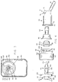
- FIG. 1 is a top plan view of a reagent bottle to which the fluid delivery system of the present invention is operatively connected
- valve assembly of the present invention is generally indicated by the reference numeral 50.
- the coupling means is generally indicated by the reference numeral 54.
- the cap assembly is generally indicated by the reference numeral 52.
- the valve assembly 50, the coupling means 54 and the cap assembly 52 are operatively connected to a reagent bottle 40 which has an interior space 42, a bottom wall 45, and a neck portion 44.
- the neck 44 of the bottle 40 has a horizontal bore 48 which extends from the outer open end of the neck to the interior space 42.
- the neck 44 has external threads 46 which are spaced from the opening 48.
- a tubular inwardly-extending projection or “blowdown” 49 extends from the neck portion 44 into the space 42 and represents one part of locking means for the valve assembly which is described hereinafter.
- the "blowdown” 49 is formed as a result of the plastic molding process and is shown somewhat exaggerated in FIG.5.
- the bottle 40 has a central longitudinal axis 47 and is designed to be supported in a generally horizontal position but at a slight angle to the horizontal as shown in FIG. 2. Also, the neck portion 44 is substantially above the central longitudinal axis 47 of the bottle.
- the cap assembly 52 comprises a cap which is generally indicated by the reference numeral 104 and a thrust washer which is generally indicated by the reference numeral 106.
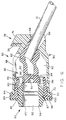
- the valve assembly 50 comprises a housing, a first embodiment of which is generally indicated by the reference numeral 56, a first valve member which is generally indicated by the reference numeral 58, a second valve member which is generally indicated by the reference numeral 60 and a tube 61 which extends from the valve assembly 50 into the interior assembled operative positions in FIG. 6 and are shown operatively connected to the coupling means 54 in FIG. 5.
- the housing 56 has a cylindrical main body portion, generally indicated by the reference numeral 69, which contains a primary bore 62 which has an air vent 68.
- the housing 56 has an outer end portion, generally indicated by the reference numeral 67, which contains an outer opening 64 to the primary bore 62 and an inner end portion, generally indicated by the reference numeral 71, which contains a secondary bore 66.
- the main body portion 69 tapers slightly from a relatively large diameter at the outer end portion 67 to a relatively small diameter at the inner end portion 71.
- the primary bore 62 has a horizontal central longitudinal axis 59.
- the secondary bore 66 extends at a downward angle from the primary bore 62 to an inner opening 73.
- the bore 62 constitutes a first chamber.
- the outer opening 64 constitutes a first outer opening of the first chamber.
- the secondary bore 66 and opening 73 constitute a first inner opening of the first chamber.
- the air vent 68 is located at the top of the bore 62 and constitutes a first intermediate opening of the bore or first chamber.
- a cam surface 65 extends at a downward angle from the primary bore 62 to the secondary bore 66.
- An annular bead 72 is located on the inwardly facing surface of the flange 70.
- Tab means is located at the inner end of the housing 56.
- Tab means 74 comprises a relatively stiff inner tab 76 and a deflectable resilient outer tab 78 which is slightly spaced from the tab 76.
- the housing 56 is preferably made of a substantially rigid thermoplastic material.
- the housing is formed by injection molding.
- the material is sufficiently rigid so that the tan 76 which is relatively broad along a line which is parallel with the longitudinal axis 59 of the housing 56 is substantially non-deflectable.
- the portion 78 which is relatively narrow along a line which is parallel with the central longitudinal axis 59 of the housing is substantially resiliently deflectable.
- the deflectable outer tab 78 extends further from the central longitudinal axis 59 of the housing than the relatively stiff inner portion 76.
- the tab 76 When the housing is inserted through the opening of the bottle 40, the tab 76 passes freely within the confines of the tubular projection 49, while the resilient tab 78 is deflected by the interior surface of the projection 49 away from the inner tab and toward the axis 59.
- the tab 78 returns to its normal position adjacent the tab 76. Movement of the housing toward the opening 48 of the bottle causes the tab portion 78 to engage the projection 49 and to deflect the tab 78 toward the tab 76.
- the tabs 78 and 76 are slightly spaced with respect to each other, the tab 78 will be deflected a slight amount until it engages the adjacent edge surface of the tab 76.
- the tab means 74 and a tubular projection 49 constitute cooperating locking means for the valve assembly 52 which enables the valve assembly to be inserted into the bottle 40 and which prevents the housing from being withdrawn from the bottle after it has been fully inserted.
- a housing to bottle joint (press or press and weld) is established to prevent torque transmitted from the cap tightening operation from rotating the housing such that downward deflection of the tube is not altered.
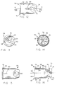
- FIGS. 35 and 36 A second embodiment of the valve housing is illustrated in FIGS. 35 and 36 and is generally indicated by the reference numeral 56'.
- Housing 56' is identical to housing 56 except that housing 56' does not have tab means 74. The housing is pressed into the bottle neck. All features of housing 56' which are identical with features of housing 56 are identified with the same reference numeral with the addition of a prime after the numeral.
- the first valve member 58 is made of an elastomeric material and comprises a relatively large diameter head portion 83 and a relatively small diameter flexible neck portion 95.
- the head portion 83 contains an outer second chamber 80 which has a second outer opening 85 and an annular ridge 87 which is adjacent the opening 85.
- An annular external flange 89 is located adjacent the second outer opening 85.
- the neck portion 95 has an inner second chamber 82 which has a second inner opening or socket 88.
- the outer and inner second chambers 80 and 82, respectively, are separated by a penetrable wall 84.
- a slit 90 is located in the wall 84 and extends from the chamber 82 to a relatively small diameter bore 93 which is connected to the chamber 80.
- the slit 90 is normally closed when the valve is in a first state due to the resilient nature of the valve member 58, so that the wall 84 normally provides a seal between the chambers 80 and 82. However, the slit 90 can be physically forced through an interference fit to an open position to create an opening between the outer and inner chambers 80 and 82, respectively, when the value is in a second or functional state.
- the chamber 80 is also connected to the outside of the valve member 58 by a plurality of air ducts 86 in the wall 84.
- the second valve member 60 comprises an elastomeric body which has an outer surface 97 and a third chamber 92.
- the chamber 92 has a third outer opening 94 and a third inner opening 96.
- An annular groove 100 is located in the outer surface 97.
- An annular ridge 102 extends from the inner surface 91 which defines the third chamber 92. The ridge 102 extends into the chamber 92 at a point approximately mid-way between the outer and inner openings 94 and 96, respectively.
- An annular flange 98 extends around the outer periphery of the valve member 60 between the outer opening 94 and the annular groove 100.
- the second valve member 60 is designed to be inserted within the outer second chamber 80 of the first valve member 58, wherein the first annular ridge 87 of the valve member 58 engages the groove 100 of the valve member 60. This ensures that the valve members 60 is properly located or seated within the chamber 80 in a predetermined position. In this predetermined position, the third inner opening 96 is closed by the wall 84. The opening 96 is horizontally aligned with the inner second chamber 82 and can be operatively connected to the chamber 82 through the hole 93 and the slit 90. However, since the slit 90 is normally closed, the chamber 80 is normally sealed from the chamber 82.
- valve member 60 When the valve member 60 is inserted within the valve member 58, the flanges 98 and 89 abut as shown in FIG. 6.
- One end of the tube or straw 61 is inserted into the socket 88.
- the joined valve members 60 and 58 are then inserted into the first chamber or primary bore 62 of the housing 56 so that the flange 89 is located between the flanges 70 and 98 as shown in FIG. 6.
- the free end of the tube 61 is inserted into the primary bore 62 and is deflected by the cam surface 65 to the secondary bore 66 and then through the secondary bore 66 so that the tube extends beyond the opening 73.
- the tube 61 and valve members 60 and 58 approach their final position as shown in FIG.
- the flexible neck portion 95 strikes the cam surface 65 and is deflected towards and into the bore 66 and forms a seal between the tube 61 and the housing 56 at the bore 66. Since the bore 66 extends at a downward angle from the valve assembly 50 so that when the valve assembly 50 is inserted into the bottle 40, the opposite end of the tube contacts the lower bottom most wall 45 of the bottle 40 as shown in FIG. 2. This ensures that substantially all of the reagent within the bottle will be aspirated. The angle of the opening 66 also causes the inner end of the valve member 58 to become distorted due to the elastomeric nature of the valve member 58 as shown in FIG. 6.
- the inner second chamber 82 is operatively connected to the interior space 42 of the bottle through the tube 61.
- the cap assembly 52 comprises a cap, generally indicated by the reference numeral 104, and a thrust washer, generally indicated by the reference numeral 106.
- the details of the thrust washer 106 are shown in FIGS. 17-20.
- Details of the cap 104 are shown in FIGS. 21-23.
- the cap 104 has a circular side wall 108 and an outer end wall 112 which is transverse to the side wall 108.
- the inner surface of the side wall 108 has internal threads 110.
- the end wall 112 has a circular outer opening 114 which is horizontally aligned with a circular inner opening 116 which is defined by the inner peripheral edge 117 of the side wall 108.
- the cap 104 has a central longitudinal axis 115 which extends through the centers of the openings 114 and 116.
- the thrust washer 106 has a circular side wall 118 and an inner end wall 119.
- the side wall 118 has an external ridge 122 and a plurality of slots 120 which create a plurality of outwardly extending segments 121.
- the outer periphery of the side wall 118 defines an outer circular opening 124.
- the inner end wall 119 is transverse to the side wall 118 and has an inner circular opening 126.
- a circular inwardly facing flange 128 is located at the outer peripheral edge of the wall 119.
- the cap assembly 52 is assembled by inserting the thrust washer 106 into the cap 104 so that the side wall 118 extends through the opening 114 of the cap.
- the outer diameter of the ridge 122 is slightly greater than the diameter of the circular opening 114.
- the thrust washer 106 and the cap are both constructed of a relatively rigid thermoplastic material by injection molding. However, the segments 121 of the thrust washer 106 are sufficiently resilient so as to be deflected toward the center of the opening 126 when they are forced against the peripheral edge of the opening 114.
- the ridge 122 has an outwardly facing beveled surface which forces each segment 121 of the wall 118 inwardly towards the central axis of the thrust washer when the wall 118 of the thrust washer is forced against the edge of the opening 114.
- the thrust washer 106 is releasably locked against movement along the axis 115 relative to the cap 104 but is free to rotate about the axis 115 relative to the cap 104.
- the fluid coupling means or coupler 54 comprises a horizontal main body portion 132 which has a central longitudinal axis 127.
- a connector fitting which is generally indicated by the reference numeral 130 is located at the outer end of the housing and a terminal nipple 134 is located at the inner end of the housing.
- the connector fitting 130 is adapted to be operatively connected to the complementary manifold fitting 55, see FIGS. 32-34, of aspirating means which forms part of an analytical instrument (not shown).
- the connector fitting 130 has an outer end surface 129 which has a circular groove 131.
- An elastomeric sealing ring 133 is located within the groove 131 and extends beyond the outer end surface 129.
- the connector fitting 130 has a relatively wide tab 137 and a relatively narrow tab 139.
- the tabs 137 and 139 are diametrically opposed and extend transversely of the longitudinal axis 127. Alternate positioning and configuration of the tabs of the connector fitting may be accomplished to engage a respective manifold fitting.
- Tab 137 has an inwardly facing engaging surface 141. One end of the surface 141 has a bevel 143.
- a flange stop 145 is located at the opposite end of the surface 141 and extends inwardly and transversely of the surface 141.
- the tab 139 has an inwardly facing engaging surface 147. One end of the surface 147 has a bevel 149.
- An annular flange 136 extends transversely from the central longitudinal horizontal axis 127 and is located adjacent and spaced from the connector fitting 130.
- a pair of fingers 144 extends from the flange 136 toward the inner end of the main body portion 132.
- a longitudinal horizontal bore 138 extends from an outer opening 140 at the fitting 130 through the main body portion 132 and the nipple 134 to an inner opening 142. The bore 138 functions as a liquid passageway.
- An annular groove 146 is located in the outer surface of the main body portion.
- a longitudinal groove 148 is located in the outer surface of the main body portion 132 and intersects the annular groove 146.
- the longitudinal groove 148 functions as a gas passageway.
- the coupling means 54 is operatively connected to the complementary manifold fitting 55 fixture of an analytical instrument which is capable of creating a suction at the opening 140.
- the manifold fitting 55 includes a manifold cavity 150 and a front opening 152 to the cavity.
- a fluid port 156 is located in an access surface 154 which forms the base of the cavity and which faces the front opening 152.
- the fluid port 156 is connected to a source of sub-atmospheric pressure, which is part of the analytical instrument (not shown).
- a first projection 158 and a second projection 160 extend toward each other at the opening 152.
- the projections 158 and 160 are spaced from each other and define therebetween a first relatively wide slot 162 and a second relatively narrow slot 164.
- the projection 158 has an inner surface 159 which is spaced from and faces the access surface 154.
- the projection 160 has an inner surface 161 which is spaced from and faces the access surface 154.
- valve assembly 50 After the valve assembly 50 has been assembled as shown in FIG.6, it is inserted into the opening 48 of the bottle 40 as shown in FIG.5.
- the valve assembly 50 is applied to the bottle 40 by inserting the assembly into the bore 48 of the neck portion 44 of the bottle in a fixed predetermined position.
- the valve assembly is inserted so that the air vent 68 of the housing 56 faces upwardly and the tube 61 extends downwardly when the bottle 40 is in a generally horizontal position as shown in FIG. 2.
- the housing is fixed to the bottle in any one of several ways.
- the housing is fixed to the neck of the bottle by fusing the flange 70 to the recessed annular edge 53 of the bottle, preferably by ultrasonic welding.
- the annular bead 72 functions as an energy director for the ultrasonic energy and is fused to the edge 53.
- valve assembly 50 is fixed to the neck of the bottle by "press fitting" the housing 56 within the bore or opening 48. This is accomplished in one of two ways. A press fit is accomplished by making the outer diameter of the insertable portion of the housing slightly smaller than the diameter of the bore 48 so that the elongated beads 63 extend beyond the diameter of the bore 48. The housing 56 is then forced into the bore 48. The beads 63 distort due to the plastic composition of the housing and enable the housing to remain in the fixed predetermined position.
- the valve assembly can also be press fitted into the bore 48 by making the outer diameter of the insertable portion of the housing slightly larger than the diameter of the bore 48.
- the inclusion of the beads 63 is optional.
- the tapered configuration of the main body portion 69 facilitates the press fitting of the housing 56.
- valve assembly can also be locked in the bottle by tab means 74 as described above.
- the cap assembly 52 is then screwed onto the neck 44 of the bottle. As the cap assembly is rotated, the flanges 98, 89 and 70 are squeezed together. This provides a liquid and air-tight seal between the valve assembly and the bottle at the neck 44.
- the thrust washer 106 stops rotating with the cap as the cap continues to be turned in the advancing direction onto the neck 44. As a result, during the cap's torquing, the thrust washer applies only a horizontal force to the elastomeric flanges 98 and 89.
- the tube 61 creates a passageway for fluid in the bottle to the inner second chamber 82, but the wall 84 prevents the fluid from passing into the chamber 80. Air within the bottle is free to enter the first chamber 62 of the housing through the air vent 68 and into the air ducts 86, but the second valve member 60 forms a seal at the openings 86 to prevent air from going beyond of the outer second chamber 80.
- a closure tab (not shown) is inserted into cap opening 114 to keep the valve assembly free of dust.
- the connector fitting 130 of the coupling means 54 is operatively connected to the complementary manifold fitting 55.
- the connector fitting 130 is inserted into the cavity 150 of the manifold fitting 55 by aligning the tab 137 with the slot 162 and the tab 139 with the slot 164 and pushing the end surface 129 toward the access surface 154.
- the coupling means 54 is then rotated clockwise to a predetermined position as viewed in FIG. 34.
- the bevels 143 and 149 engage the inner surfaces 159 and 161, respectively and function as cam surfaces to guide the tabs 137 and 139 between each of the first and second projections 158 and 160, respectively, and the access surface 154.
- the bevels 143 and 149 are biased against the surfaces 159 and 161, respectively, by the elastomeric sealing ring 133.
- the coupling means 54 is rotated about the axis 127 for approximately 90°, at which point the flange 145 engages the adjacent edge 163 of the projection 158 to prevent further rotation.
- the longitudinal groove 148 faces upwardly as shown in FIG. 34.
- Connector fitting 130 of the coupling means 54 is operatively connected to the manifold fitting 55 as shown in FIG. 34.
- the opening 140 of the bore 138 is axially aligned with the port 156 so that the port 156 is operatively connected to the bore or liquid passageway 138.
- the coupling means 54 is operatively connected to the valve assembly by moving the bottle toward the manifold so that the coupling means extends horizontally into the third chamber 92.
- the nipple 134 enters into the small diameter bore 93, thereby expanding the bore 93 and simultaneously expanding the slit 90 sufficiently to allow the nipple to penetrate the wall 84 and extend into the inner second chamber 82 as shown in FIG. 5.
- the shoulder 135 of the main body portion engages the wall 84 and forces the wall 84 away from the inner end of the second valve member 60, thereby creating a passageway between the chamber 62 and the chamber 80.
- the annular ridge 102 of the second valve member engages the annular groove 146 of the coupling means 54 so that the coupling means is properly located within the valve assembly at a predetermined location relative to the valve assembly.
- the fingers 144 engage the outer wall 112 of the cap 104 to prevent the coupling means from going beyond this predetermined position.
- the fingers 144 also function as finger grips for enabling an operator to easily connect and disconnect the coupling means 54 to the manifold fitting 55.
- the inner end of the groove 148 extends into the outer second chamber 80.
- the outer end of the groove 148 extends beyond the cap assembly 52 to create an air or gas passageway between the chamber 80 to a point outside of the bottle cap.
- the bottle When the bottle is connected to the coupling means 54, it is supported on a slightly inclined supporting tray 170, which forms part of the analyzing instrument (not shown).
- the bottle is supported in a substantially horizontal position and with a slight upward tilt toward the opening of the bottle due to the inclined angle of the supporting tray.
- the bottle is filled with fluid to the extent that the fluid is just below the air vent 68 and the groove 148 so that these elements lie in the air space above the top of the bottle above the fluid.
Landscapes
- Mechanical Engineering (AREA)
- Engineering & Computer Science (AREA)
- Health & Medical Sciences (AREA)
- Chemical & Material Sciences (AREA)
- Analytical Chemistry (AREA)
- Life Sciences & Earth Sciences (AREA)
- Physics & Mathematics (AREA)
- Biochemistry (AREA)
- General Health & Medical Sciences (AREA)
- General Physics & Mathematics (AREA)
- Immunology (AREA)
- Pathology (AREA)
- Chemical Kinetics & Catalysis (AREA)
- Clinical Laboratory Science (AREA)
- Closures For Containers (AREA)
- Feeding, Discharge, Calcimining, Fusing, And Gas-Generation Devices (AREA)
- Loading And Unloading Of Fuel Tanks Or Ships (AREA)
- Jet Pumps And Other Pumps (AREA)
- Infusion, Injection, And Reservoir Apparatuses (AREA)
- Automatic Analysis And Handling Materials Therefor (AREA)
- Measurement Of Radiation (AREA)
- Piezo-Electric Or Mechanical Vibrators, Or Delay Or Filter Circuits (AREA)
- Finger-Pressure Massage (AREA)
- Devices For Dispensing Beverages (AREA)
- Sampling And Sample Adjustment (AREA)
- Nozzles (AREA)
- Acyclic And Carbocyclic Compounds In Medicinal Compositions (AREA)
- Reciprocating Pumps (AREA)
- Centrifugal Separators (AREA)
- Cyclones (AREA)
- Quick-Acting Or Multi-Walled Pipe Joints (AREA)
- Pressure Vessels And Lids Thereof (AREA)
Claims (13)
- Fluidaustragsystem zum Absaugen von Flüssigkeit aus einer Flasche (40) und zum Fördern der Flüssigkeit zu einem Verteileranschluß (55) eines Analyseinstruments, wobei die Flasche einen Innenraum aufweist, der eine Flüssigkeitsmenge enthält, und eine Öffnung zum Innenraum, wobei der Verteileranschluß an eine Unterdruckquelle angeschlossen ist, wobei das Fluidaustragsystem aufweist:(a) einen Ventilaufbau (50) zur Anordnung in einer Öffnung einer Flasche (40), wobei der Ventilaufbau einen Flüssigkeitskanal und einen Gaskanal aufweist, die geschlossen sind, wenn der Ventilaufbau sich in einem ersten Zustand zum Verhindern des Gasstroms in die Flasche hinein und des Flüssigkeitsstroms aus der Flasche heraus aufweist, und die offen sind, wenn der Ventilaufbau sich in einem zweiten Funktionszustand befindet, in welchem Gas in die Flasche hinein von der Außenseite der Flasche aus strömen gelassen wird und Flüssigkeit aus der Flasche heraus durch den Ventilaufbau zu dem Verteileranschluß (55) strömengelassen wird,(b) ein Rohr (61), das sich ausgehend vom Ventilaufbau (50) in die Flüssigkeit innerhalb des Innenraums der Flasche (40) hineinerstreckt, und(c) eine Fluidkupplungseinrichtung (54) mit einem äußeren Ende und einem inneren Ende, wobei das äußere Ende ein Anschlußteil (130) aufweist, der komplementär zu dem Verteileranschluß (55) ist, damit er mit dem Verteileranschluß lösbar betriebsmäßig verbunden werden kann, wobei das innere Ende dazu ausgelegt ist, lösbar betriebsmäßig mit dem Ventilaufbau (50) verbunden zu werden, um den Ventilaufbau in den zweiten oder funktionellen Zustand zu überführen, wobei die Fluidkupplungseinrichtung einen Flüssigkeitsdurchlaß aufweist, der betriebsmäßig mit dem Flüssigkeitskanal verbunden ist, und einen Gasdurchlaß, der betriebsmäßig mit dem Gaskanal verbunden ist, wenn die Fluidkupplungseinrichtung betriebsmäßig mit dem Ventilaufbau verbunden ist, wobei der Flüssigkeitsdurchlaß sich vom inneren Ende zum äußeren Ende erstreckt, damit Flüssigkeit durch das Analyseinstrument aus der Flasche (40) durch das Rohr, den Ventilaufbau und den Flüssigkeitsdurchlaß zu dem Verteileranschluß gezogen werden kann, wobei der Gasdurchlaß sich vom inneren Ende in direkter Verbindung mit dem Gaskanal zu einem Punkt außerhalb der Flasche erstreckt, damit Luft von der Außenseite der Flasche durch den Gasdurchlaß und den Gaskanal in den Innenraum der Flasche strömen kann, wobei die Kupplungseinrichtung mit dem Ventilaufbau eine dichtende Beziehung aufweist, die den Luftstrom von der umgebenden Atmosphäre in die Flasche hinein und ausschließlich durch den Gasdurchlaß und den Gaskanal hindurch beschränkt, und die den Flüssigkeitsdurchlaß von der Flasche zu der Absaugeinrichtung ausschließlich durch den Flüssigkeitsdurchlaß und den Flüssigkeitskanal beschränkt, wobei das Fluidaustragsystem dadurch gekennzeichnet ist, daß der Ventilaufbau (50) aufweist:(a) ein Gehäuse (56, 56') zur Anordnung an der Öffnung und dazu dienend, sich in die Flasche (40) zu erstrecken, wobei das Gehäuse eine erste Kammer (62) aufweist, wobei die Kammer eine innerhalb der Öffnung der Flasche gelegene erste äußere Öffnung (64) aufweist, eine erste innere Öffnung (66, 73) und eine erste zwischengeschaltete Öffnung (68), wobei die erste innere Öffnung und die zwischengeschaltete Öffnung zur betriebsmäßigen Verbindung mit dem Innenraum der Flasche dienen,(b) ein erstes elastomeres Ventilelement (58), das innerhalb der ersten Kammer (62) angeordnet ist, wobei das erste elastomere Ventilelement eine äußere zweite Kammer (80), eine innere zweite Kammer (82) und eine durchdringbare Wand (84) zwischen der inneren Kammer und der äußeren zweiten Kammer aufweist, die normalerweise die innere zweite Kammer von der äußeren zweiten Kammer abdichtet, wobei die äußere zweite Kammer eine zweite äußere Öffnung (85) aufweist, die innerhalb der ersten äußeren Öffnung und der Öffnung der Flasche gelegen ist, und eine Luftdurchführung (86) in der durchdringbaren Wand, die sich von der äußeren zweiten Kammer zu der ersten Kammer (62) erstreckt, wobei die innere zweite Kammer eine zweite innere Öffnung (88) zu der ersten inneren Öffnung (66, 73) aufweist, wobei das Rohr (61) ein erstes offenes Ende aufweist, das innerhalb der ersten inneren Öffnung und der zweiten inneren Öffnung angeordnet ist, und ein zweites offenes Ende, das dazu ausgelegt ist, sich in die Flüssigkeit innerhalb der Flasche zu erstrecken, um einen Kanal für einen Flüssigkeitsstrom von der Flasche (40) in die zweite äußere Kammer (80) zu bilden, wobei das erste elastomere Ventilelement eine Dichtung an der ersten inneren Öffnung zwischen dem Rohr (61) und dem Gehäuse (56, 56') bildet, und(c) ein zweites elastomeres Ventilelement (60), das innerhalb der äußeren zweiten Kammer (80) angeordnet ist, wobei das zweite Ventilelement eine dritte Kammer (92) aufweist, wobei die dritte Kammer eine dritte äußere Öffnung (94) innerhalb der zweiten äußeren Öffnung (85) und der Öffnung zu der Flasche (40) aufweist, und eine dritte innere Öffnung (96), die zu der durchdringbaren Wand (84) weist und durch die durchdringbare Wand vrschlossen ist, wobei das zweite Ventilelement in Eingriff mit der durchdringbaren Wand steht, um die Luftdurchführung zu blockieren, wobei das innere Ende der Kupplungseinrichtung (54) dazu dient, die durchdringbare Wand (84) zu verschieben, um die Luftdurchführung derart freizugeben, daß die Luftdurchführung eine Verbindung zwischen der ersten Kammer (62) und der dritten Kammer (92) bildet, wobei das innere Ende der Kupplungseinrichtung dazu dient, die Wand zwischen der inneren und der äußeren zweiten Kammer (80, 82) derart zu durchdringen, daß das innere Ende der Kupplung sich in die zweite Kammer (82) hineinerstreckt und der Flüssigkeitsdurchlaß der Kupplungseinrichtung betriebsmäßig mit der inneren zweiten Kammer (82) verbunden ist.
- Fluidaustragsystem nach Anspruch 1, wobei die durchdringbare Wand (84) einen Schlitz (90) aufweist, der normalerweise aufgrund der elastomeren Natur des ersten Ventilelements (58) verschlossen ist, und wobei das innere Ende der Kupplungseinrichtung (54) einen relativ schmalen Abschlußnippel (134) aufweist, der sich durch den Schlitz (90) in die innere Kammer hineinerstreckt, indem das elastomere Material um den Schlitz herum versetzt bzw. verschoben wird, wobei die Kupplungseinrichtung eine Schulter (135) aufweist, die zur durchdringbaren Wand (84) weist, um die Wand von der dritten inneren Öffnung (96) des zweiten Ventilaufbaus (60) wegzuschieben.
- Fluidaustragsystem nach Anspruch 1, wobei das zweite Ventilelement (60) innerhalb des ersten Ventilelements (58) entfernbar angebracht ist, wobei das erste Ventilelement und das zweite Ventilelement eine erste komplementäre Lokalisiereinrichtung (87, 100) aufweisen, um sicherzustellen, daß das zweite Ventilelement in einer vorbestimmten Position innerhalb des ersten Ventilelements angeordnet ist, und wobei das zweite Ventilelement und die Kupplungseinrichtung (54) zweite komplementäre Lokalisiereinrichtung (102, 146) aufweisen, um sicherzustellen, daß die Kupplungseinrichtung sich in einer vorbestimmten Position innerhalb des zweiten Ventilelements befindet.
- Fluidaustragsystem nach Anspruch 3, wobei die erste komplementäre Lokalisiereinrichtung eine erste ringförmige Nut (100) entweder im ersten Ventilelement oder im zweiten Ventilelement und eine erste ringförmige Rippe (87) in dem jeweils anderen der ersten und zweiten Ventilelemente aufweist, wobei die erste ringförmige Rippe sich in die erste ringförmige Nut hineinerstreckt, und wobei die zweite komplementäre Lokalisiereinrichtung eine zweite ringförmige Nut (146) entweder in dem zweiten Ventilelement oder der Kupplungseinrichtung und eine zweite ringförmige Rippe (102) in dem nutfreien zweiten Ventilelement bzw. der Kupplungseinrichtung aufweist, und wobei die zweite ringförmige Rippe sich in die zweite ringförmige Nut hineinerstreckt.
- Fluidaustragsystem nach Anspruch 1, wobei die Kupplungseinrichtung (54) eine Außenseite aufweist und wobei das zweite Ventilelement (60) eine Innenseite aufweist, die die dritte Kammer (92) festlegt und an der Außenseite der Kupplungseinrichtung anliegt, und wobei der Gasdurchlaß eine längliche Nut (148) in einer Außenseite der Kupplungseinrichtung ist, die zur Innenseite des zweiten Ventilelements weist.
- Fluidaustragsystem nach Anspruch 1, wobei der Ventilaufbau aufweist:(a) ein Gehäuse (56, 56'), daß an der Öffnung angeordnet und dazu ausgelegt ist, sich in den Innenraum der Flasche (40) zu erstrecken, wobei das Gehäuse eine erste Kammer (62) aufweist,(b) ein erstes elastomeres Ventilelement (58), das innerhalb der ersten Kammer (62) angeordnet ist, wobei das erste Ventilelement eine zweite Kammer (80, 82) aufweist, und(c) ein zweites elastomeres Ventilelement (60), das innerhalb der zweiten Kammer angeordnet ist, wobei das zweite elastomere Ventilelement eine dritte Kammer (92) zum Aufnehmen des inneren Endes der Kupplungseinrichtung (54) aufweist, wenn die Kupplungseinrichtung betriebsmäßig mit dem Ventilaufbau verbunden ist, wobei das zweite elastomere Ventilelement einen Fluidkanal aufweist, der zum betriebsmäßigen Verbinden des Rohrs mit dem Flüssigkeitsdurchlaß dient, wobei das erste elastomere Ventilelement und das zweite elastomere Ventilelement gemeinsam einen Gaskanal bilden, der zum betriebsmäßigen Verbinden des Innenraums der Flasche mit dem Gasdurchlaß dient.
- Fluidaustragsystem nach Anspruch 6, wobei der Ventilaufbau (50) dazu ausgelegt ist, eine mit der Flasche (40) zusammenwirkende Verriegelungseinrichtung bereitzustellen, damit der Ventilaufbau durch die Öffnung der Flasche in den Innenraum der Flasche eingeführt werden kann, und um zu verhindern, daß der Ventilaufbau aus der Flasche herausgezogen wird.
- Fluidaustragsystem nach Anspruch 7 für eine Verwendung, bei welcher die zusammenwirkende Verriegelungseinrichtung einen relativ steifen Vorsprung (49) aufweist, der einen Teil der Flasche bildet und sich von der Öffnung der Flasche in den Innenraum der Flasche erstreckt, wobei die Verriegelungseinrichtung außerdem eine Zungeneinrichtung (76, 78) aufweist, die einen Teil des Gehäuses (56) bildet und sich quer ausgehend vom Gehäuse erstreckt, wobei die Zungeneinrichtung so aufgebaut ist, daß sie sich an dem Vorsprung vorbeibewegen kann, wenn das Gehäuse durch die Öffnung der Flasche in eine innere Position innerhalb des Innenraums eingeführt wird, und um zu verhindern, daß die Zungeneinrichtung sich an dem Vorsprung vorbeibewegt, wenn das Gehäuse aus der inneren Position in Richtung auf die Öffnung der Flasche bewegt wird.
- Fluidaustragsystem nach Anspruch 8, zur Verwendung, bei welcher die Öffnung der Flasche (40) eine Mittenlängsachse (47) aufweist, und wobei der Vorsprung (49) sich unter einem vorbestimmten Abstand von der Achse befindet, wobei die Zungeneinrichtung einen relativ steifen inneren Zungenabschnitt (76) an einem inneren Ende des Gehäuses (56) und einen relativ auslenkbaren und nachgiebigen bzw. federnden äußeren Zungenabschnitt (78) aufweist, der mit dem inneren Zungenabschnitt entlang einer Linie fluchtet, die parallel zu der Achse verläuft, wobei der innere Zungenabschnitt sich zu einem Punkt erstreckt, der näher zu der Achse liegt als der Vorsprung, wobei der äußere Zungenabschnitt sich zu einem Punkt erstreckt, der weiter entfernt von der Achse liegt als der Vorsprung, so daß dann, wenn das Gehäuse durch die Öffnung der Flasche eingeführt wird, der äußere Zungenabschnitt in Richtung auf die Achse durch den Vorsprung ausgelenkt wird, bis der äußere Zungenabschnitt das Ende des Vorsprungs erreicht, woraufhin der äußere Abschnitt in seine normale Orientierung relativ zu der Achse zurückkehrt und innerhalb des Vorsprungs sowie fluchtend mit dem Vorsprung liegt, wobei der äußere Abschnitt durch den inneren Zungenabschnitt daran gehindert wird, in Richtung auf die Achse durch den Vorsprung ausgelenkt zu werden, wenn das Gehäuse in Auswärtsrichtung gezwungen bzw. gedrängt wird.
- Fluidaustragsystem nach Anspruch 9, wobei der äußere Zungenabschnitt (78) geringfügig von dem inneren Zungenabschnitt (76) beabstandet ist, und wobei sowohl der innere Zungenabschnitt wie der äußere Zungenabschnitt eine Endseite bzw. Endfläche aufweist, die von der Achse am weitesten entfernt und in Richtung auf die Achse in Einwärtsrichtung verjüngt ist.
- Fluidaustragsystem nach Anspruch 9, wobei der innere Zungenabschnitt (76) wesentlich breiter ist als der äußere Zungenabschnitt (78) in einer Richtung, die längs zu der Achse verläuft, und wobei die Differenz des relativen Federungsvermögens zwischen den inneren und äußeren Zungenabschnitten auf dieser Breitendifferenz zwischen dem inneren Zungenabschnitt und dem äußeren Zungenabschnitt beruht.
- Fluidaustragsystem nach Anspruch 1, wobei das Fluidaustragsystem zur Verwendung mit einer Flasche (40) dient, die einen Halsabschnitt (44) aufweist, der die Öffnung zum Innenraum der Flasche enthält, wobei der Halsabschnitt ein Außengewinde (46) aufweist, eine Bohrung (48) zum Aufnehmen des Ventilaufbaus (50) und eine Gegenbohrung, die mit der Bohrung eine auswärtsweisende ringförmige Schulter (53) festlegt, und wobei der Ventilaufbau einen ringförmigen Flansch (70) aufweist, der im Eingriff mit der Schulter steht, und wobei das Fluidaustragsystem außerdem einen Deckel (104) aufweist, der eine Endwand aufweist, die eine Öffnung für die Kupplungseinrichtung (54) hat, wobei der Deckel eine Seitenwand (108) aufweist, die ein Innengewinde (110) zum Eingriff mit dem Außengewinde hat, und zum Schrauben des Deckels (104) auf dem Halsabschnitt und zum Klemmen des ringförmigen Flansches (70) zwischen die Schulter und die Außenwand des Deckels.
- Fluidaustragsystem nach Anspruch 12, wobei das Fluidaustragsystem außerdem eine Druck- bzw. Sicherungsscheibe (106) aufweist, die zwischen der Außenwand des Deckels (104) und dem ringförmigen Flansch (70) des Ventilaufbaus (50) so angeordnet ist, daß der Deckel sich relativ zu der Druckscheibe beim Zusammendrücken des ringförmigen Flansches dreht, wenn der Deckel auf den Halsabschnitt (44) geschraubt wird.
Priority Applications (2)
| Application Number | Priority Date | Filing Date | Title |
|---|---|---|---|
| EP97203233A EP0825148B1 (de) | 1993-12-09 | 1994-07-21 | Kappenbaugruppe |
| EP97203232A EP0829451B1 (de) | 1993-12-09 | 1994-07-21 | Flüssigkeitsabgabesystem |
Applications Claiming Priority (2)
| Application Number | Priority Date | Filing Date | Title |
|---|---|---|---|
| US165137 | 1993-12-09 | ||
| US08/165,137 US5755269A (en) | 1993-12-09 | 1993-12-09 | Fluid delivery system |
Related Child Applications (2)
| Application Number | Title | Priority Date | Filing Date |
|---|---|---|---|
| EP97203233A Division EP0825148B1 (de) | 1993-12-09 | 1994-07-21 | Kappenbaugruppe |
| EP97203232A Division EP0829451B1 (de) | 1993-12-09 | 1994-07-21 | Flüssigkeitsabgabesystem |
Publications (3)
| Publication Number | Publication Date |
|---|---|
| EP0657382A2 EP0657382A2 (de) | 1995-06-14 |
| EP0657382A3 EP0657382A3 (de) | 1995-07-19 |
| EP0657382B1 true EP0657382B1 (de) | 1998-06-17 |
Family
ID=22597583
Family Applications (3)
| Application Number | Title | Priority Date | Filing Date |
|---|---|---|---|
| EP97203233A Expired - Lifetime EP0825148B1 (de) | 1993-12-09 | 1994-07-21 | Kappenbaugruppe |
| EP97203232A Expired - Lifetime EP0829451B1 (de) | 1993-12-09 | 1994-07-21 | Flüssigkeitsabgabesystem |
| EP94305376A Expired - Lifetime EP0657382B1 (de) | 1993-12-09 | 1994-07-21 | Flüssigkeitsabgabesystem |
Family Applications Before (2)
| Application Number | Title | Priority Date | Filing Date |
|---|---|---|---|
| EP97203233A Expired - Lifetime EP0825148B1 (de) | 1993-12-09 | 1994-07-21 | Kappenbaugruppe |
| EP97203232A Expired - Lifetime EP0829451B1 (de) | 1993-12-09 | 1994-07-21 | Flüssigkeitsabgabesystem |
Country Status (11)
| Country | Link |
|---|---|
| US (4) | US5755269A (de) |
| EP (3) | EP0825148B1 (de) |
| JP (2) | JP2858634B2 (de) |
| KR (1) | KR950017725A (de) |
| AT (3) | ATE207851T1 (de) |
| AU (1) | AU689473B2 (de) |
| CA (1) | CA2125217A1 (de) |
| DE (3) | DE69411134T2 (de) |
| DK (3) | DK0657382T3 (de) |
| ES (3) | ES2117213T3 (de) |
| PL (1) | PL306124A1 (de) |
Cited By (1)
| Publication number | Priority date | Publication date | Assignee | Title |
|---|---|---|---|---|
| US6562298B1 (en) | 1996-09-19 | 2003-05-13 | Abbott Laboratories | Structure for determination of item of interest in a sample |
Families Citing this family (57)
| Publication number | Priority date | Publication date | Assignee | Title |
|---|---|---|---|---|
| US5803909A (en) * | 1994-10-06 | 1998-09-08 | Hitachi, Ltd. | Optical system for measuring metabolism in a body and imaging method |
| US5884679A (en) * | 1995-08-11 | 1999-03-23 | Bissell Inc. | Solution dispensing bottle assembly |
| US5862948A (en) | 1996-01-19 | 1999-01-26 | Sc Johnson Commerical Markets, Inc. | Docking station and bottle system |
| GB9623544D0 (en) * | 1996-11-12 | 1997-01-08 | Micromass Ltd | Sample vial and vial closure device for use in gas analysis and method of using the same |
| WO1998042962A1 (fr) * | 1997-03-21 | 1998-10-01 | Tamotsu Takahara | Bouchon de vidange pour reservoir d'huile et dispositif de vidange mettant ce bouchon en application |
| DE29705992U1 (de) * | 1997-04-03 | 1998-07-30 | Dürr-Dental GmbH & Co KG, 74321 Bietigheim-Bissingen | Dosierbehälter |
| GB2333514B (en) * | 1998-01-21 | 2002-04-24 | Eastman Kodak Co | Mounting arrangement |
| US6184137B1 (en) | 1998-11-25 | 2001-02-06 | Applied Materials, Inc. | Structure and method for improving low temperature copper reflow in semiconductor features |
| US6142343A (en) * | 1998-12-30 | 2000-11-07 | Steris Inc | Cap and dust cover for an antiseptic soap dispenser |
| DE19956568A1 (de) * | 1999-01-30 | 2000-08-17 | Roland Kreutzer | Verfahren und Medikament zur Hemmung der Expression eines vorgegebenen Gens |
| US6202717B1 (en) | 1999-08-05 | 2001-03-20 | S. C. Johnson Commercial Markets, Inc. | Dispensing bottle closure |
| US6378742B1 (en) | 2000-10-10 | 2002-04-30 | Rieke Corporation | Fluid dispensing closure |
| US6367657B1 (en) * | 2001-02-05 | 2002-04-09 | Samhongsa, Co., Ltd. | Control valve for a gas cylinder |
| JP4866005B2 (ja) | 2002-08-13 | 2012-02-01 | メディカル・インスティル・テクノロジーズ・インコーポレイテッド | 内容物蓄蔵吐出用の容器及びこれに関連する方法 |
| EP1400283B1 (de) * | 2002-09-20 | 2009-11-18 | Becton Dickinson and Company | Rollflasche |
| EP1636091A2 (de) | 2003-05-12 | 2006-03-22 | Medical Instill Technologies, Inc. | Abgabevorrichtung und vorrichtung zum füllen einer abgabevorrichtung |
| US7226231B2 (en) | 2003-07-17 | 2007-06-05 | Medical Instill Technologies, Inc. | Piston-type dispenser with one-way valve for storing and dispensing metered amounts of substances |
| JPWO2005037413A1 (ja) * | 2003-10-17 | 2007-11-22 | 富士フイルム株式会社 | 多孔質膜カートリッジ |
| US7431890B2 (en) * | 2003-11-17 | 2008-10-07 | Sakura Finetek U.S.A., Inc. | Fluid system coupler |
| US7040515B2 (en) * | 2003-11-24 | 2006-05-09 | Cactrus Drink Systems Inc. | Bottle cap |
| US7264142B2 (en) | 2004-01-27 | 2007-09-04 | Medical Instill Technologies, Inc. | Dispenser having variable-volume storage chamber and depressible one-way valve assembly for dispensing creams and other substances |
| US8789725B2 (en) * | 2004-03-29 | 2014-07-29 | P G United States Israel Ltd. | Foam dispenser nozzle |
| US20060173436A1 (en) * | 2005-01-14 | 2006-08-03 | Kimberly-Clark Worldwide, Inc. | Disposable absorbent article having a waist opening with a scalloped edge |
| US7896859B2 (en) * | 2005-10-20 | 2011-03-01 | Tyco Healthcare Group Lp | Enteral feeding set |
| US7611502B2 (en) * | 2005-10-20 | 2009-11-03 | Covidien Ag | Connector for enteral fluid delivery set |
| JP5048968B2 (ja) * | 2006-05-08 | 2012-10-17 | サーパス工業株式会社 | コネクタ構造 |
| US7637397B2 (en) * | 2006-08-25 | 2009-12-29 | S.C. Johnson & Son, Inc. | Flexible down tube and methods of use thereof |
| US20080223812A1 (en) * | 2007-03-13 | 2008-09-18 | Tomasz Domagala | Bottled Beverage Plug for Identification |
| US7806303B1 (en) * | 2007-10-11 | 2010-10-05 | Mark Hastings | Sealable pour spout |
| KR100873915B1 (ko) * | 2007-11-01 | 2008-12-12 | 주식회사 아이센스 | 혈액 분석 장치용 용액 용기 |
| US8251346B2 (en) * | 2008-03-04 | 2012-08-28 | Infusion Innovations, Inc. | Devices, assemblies, and methods for controlling fluid flow |
| US8414542B2 (en) * | 2008-03-04 | 2013-04-09 | Infusion Innovations, Inc. | Devices, assemblies, and methods for controlling fluid flow |
| US20100123019A1 (en) * | 2008-11-14 | 2010-05-20 | Hydroback Hydration Systems, Llc | Bottle adaptor for personal hydration system |
| CN102308138B (zh) * | 2009-01-09 | 2013-08-14 | 利基-博克斯公司 | 用于可折叠容器的鸭嘴翻转帽配件 |
| US8408429B2 (en) | 2009-11-11 | 2013-04-02 | The Clorox Company | Bottle with integral dip tube |
| US8297479B2 (en) * | 2009-11-11 | 2012-10-30 | The Clorox Company | Shrink sleeve on bottle with integral dip tube |
| US8603047B2 (en) | 2010-12-15 | 2013-12-10 | Infusion Innovations | Devices, assemblies and methods for controlling fluid flow |
| US9849277B2 (en) | 2010-12-15 | 2017-12-26 | Infusion Innovations, Inc. | Devices, assemblies and methods for controlling fluid flow |
| EP2691177B1 (de) | 2011-03-28 | 2018-07-25 | Corning Incorporated | Behälterkappe mit einem knickbeständigen verbinder |
| US8789728B2 (en) * | 2012-01-03 | 2014-07-29 | Scott Huffman | Liquid spray dispenser suction tube deflector |
| US20140094727A1 (en) * | 2012-09-28 | 2014-04-03 | Covidien Lp | Compression device pumping |
| GB2513006B (en) | 2013-03-15 | 2016-01-27 | Bissell Homecare Inc | Container and cap assembly |
| US10299993B2 (en) | 2015-07-08 | 2019-05-28 | Infusion Innovations, Inc. | Valve assembly and methods of use |
| US10143350B2 (en) | 2015-09-09 | 2018-12-04 | Bissell Homecare, Inc. | Cap and receiver for coupling a container to a surface cleaning device |
| CN109854794B (zh) * | 2019-03-01 | 2021-01-19 | 中国科学院合肥物质科学研究院 | 一种等离子体破裂防护专用的压差式快速充气阀 |
| US12213617B2 (en) | 2022-05-13 | 2025-02-04 | Sharkninja Operating Llc | Flavored beverage carbonation process |
| US11647860B1 (en) | 2022-05-13 | 2023-05-16 | Sharkninja Operating Llc | Flavored beverage carbonation system |
| US11751585B1 (en) | 2022-05-13 | 2023-09-12 | Sharkninja Operating Llc | Flavored beverage carbonation system |
| US12096880B2 (en) | 2022-05-13 | 2024-09-24 | Sharkninja Operating Llc | Flavorant for beverage carbonation system |
| US11634314B1 (en) | 2022-11-17 | 2023-04-25 | Sharkninja Operating Llc | Dosing accuracy |
| US12103840B2 (en) | 2022-11-17 | 2024-10-01 | Sharkninja Operating Llc | Ingredient container with sealing valve |
| US12084334B2 (en) | 2022-11-17 | 2024-09-10 | Sharkninja Operating Llc | Ingredient container |
| US11745996B1 (en) | 2022-11-17 | 2023-09-05 | Sharkninja Operating Llc | Ingredient containers for use with beverage dispensers |
| US11738988B1 (en) | 2022-11-17 | 2023-08-29 | Sharkninja Operating Llc | Ingredient container valve control |
| US12116257B1 (en) | 2023-03-22 | 2024-10-15 | Sharkninja Operating Llc | Adapter for beverage dispenser |
| US11925287B1 (en) | 2023-03-22 | 2024-03-12 | Sharkninja Operating Llc | Additive container with inlet tube |
| US11871867B1 (en) | 2023-03-22 | 2024-01-16 | Sharkninja Operating Llc | Additive container with bottom cover |
Family Cites Families (76)
| Publication number | Priority date | Publication date | Assignee | Title |
|---|---|---|---|---|
| US1250058A (en) * | 1916-12-29 | 1917-12-11 | Harry Weaver | Jar-closure. |
| US1679735A (en) * | 1922-03-14 | 1928-08-07 | Bassick Mfg Co | Lubricating apparatus |
| US1482373A (en) * | 1922-03-16 | 1924-01-29 | James H Wallace | Stopper |
| US1750512A (en) * | 1927-11-25 | 1930-03-11 | Romort Mfg Company | Liquid-spraying device |
| US1952437A (en) * | 1932-08-05 | 1934-03-27 | Ward I Huber | Dispensing device for liquid containers |
| US2075249A (en) * | 1935-11-23 | 1937-03-30 | Ralph W Wilson | Closure for containers |
| US2149681A (en) * | 1937-01-25 | 1939-03-07 | Carey W Johnston | Control device |
| US2190054A (en) * | 1937-08-30 | 1940-02-13 | Cutter Lab | Flask and stopper therefor |
| US2288565A (en) * | 1940-05-31 | 1942-06-30 | Mine Safety Appliances Co | Breathing apparatus supply valve |
| US2416829A (en) * | 1944-12-29 | 1947-03-04 | Parker Appliance Co | Closure cap for tube fittings |
| US2526630A (en) * | 1948-06-03 | 1950-10-24 | Thomas N Bourke | Seal device for containers |
| US2598403A (en) * | 1950-07-15 | 1952-05-27 | Macey John | Dispensing bottle stopper |
| US2860820A (en) * | 1953-07-30 | 1958-11-18 | Prepo Corp | Assembly and locking means for liquid handling devices |
| US2851201A (en) * | 1955-02-01 | 1958-09-09 | Edward J Poitras | Automatic vent stopper |
| US2822054A (en) * | 1955-05-09 | 1958-02-04 | Gen Pacific Corp | Fire extinguisher |
| US2992762A (en) * | 1958-06-26 | 1961-07-18 | Forman Benjamin | Flow controlling bottle closures |
| US3143235A (en) * | 1958-10-30 | 1964-08-04 | Lowen Stanley | Container closure |
| US3067898A (en) * | 1959-05-18 | 1962-12-11 | Baxter Laboratories Inc | Parenteral solution equipment |
| US3084823A (en) * | 1959-08-13 | 1963-04-09 | Reichstein Jozef | Stoppers for vessels, especially for bottles with gaseous or sparkling liquids |
| US3065885A (en) * | 1960-02-18 | 1962-11-27 | Anheuser Busch | Beer barrel tapping device |
| US3157323A (en) * | 1961-04-12 | 1964-11-17 | Nat Products Co | Valve closure for bottles and the like |
| US3233793A (en) * | 1963-09-03 | 1966-02-08 | Seaquist Valve Co | Aerosol valve |
| US3232485A (en) * | 1964-02-11 | 1966-02-01 | Reynolds Metals Co | Charging valve construction |
| US3324903A (en) * | 1965-05-12 | 1967-06-13 | Hinz Karl | Syphons adapted to contain and dispense soda water |
| US3460569A (en) * | 1966-01-19 | 1969-08-12 | Aeroquip Corp | Identical halves coupling |
| US3438553A (en) * | 1967-01-04 | 1969-04-15 | Johnston Enterprises Inc | Tapping device for beer kegs and the like |
| US3467270A (en) * | 1967-08-03 | 1969-09-16 | Hall Robert M | Cap |
| US3499568A (en) * | 1967-12-28 | 1970-03-10 | Jose Vinas Riera | Stopper system for biological containers |
| US3512806A (en) * | 1968-01-22 | 1970-05-19 | Russell H Romney | Adapter for multiple connections to intravenous fluid receptacles and the like |
| US3596810A (en) * | 1969-09-02 | 1971-08-03 | Perlick Co Inc The | Keg-tapping system |
| BE794248A (fr) * | 1972-02-22 | 1973-05-16 | Baxter Laboratories Inc | Perfectionnements apportes aux fermetures steriles pour bouteilles ou flacons a solution |
| DE2212817A1 (de) * | 1972-03-16 | 1973-09-27 | Kathrein Werke Kg | Schnellanschluss fuer koaxialkabel |
| US3923183A (en) * | 1973-03-07 | 1975-12-02 | American Hospital Supply Corp | Container for medical liquid with separable outer and inner closures |
| US4022205A (en) * | 1973-11-05 | 1977-05-10 | Tenczar Francis J | Fluid connectors |
| US4089444A (en) * | 1974-03-11 | 1978-05-16 | Shea Ronald E | Tapping apparatus for golden gate type beer keg openings |
| US4136796A (en) * | 1974-04-11 | 1979-01-30 | Greif Bros. Corporation | Vented closure |
| AU1414976A (en) * | 1975-05-21 | 1977-11-24 | Mobil Oil Australia | Drain valve |
| US4065018A (en) * | 1976-08-02 | 1977-12-27 | William J. Megowen | Closure means and method |
| GB1530968A (en) * | 1976-09-17 | 1978-11-01 | Grundy Ltd | Coupling or dispensing heads for pressurised casks and like containers |
| US4065081A (en) * | 1976-12-09 | 1977-12-27 | General Signal Corporation | Alternating current track circuits |
| US4238131A (en) * | 1978-06-12 | 1980-12-09 | Cleveland Marvin G | Flushing T for heater hose |
| US4265280A (en) * | 1979-01-23 | 1981-05-05 | Baxter Travenol Laboratories, Inc. | Connector member for sealed conduits |
| FR2469641A1 (fr) * | 1979-11-15 | 1981-05-22 | Gleizes Raymond | Dispositif pour le raccordement etanche de deux troncons cylindriques creux tels que tuyaux elements de raccords et analogues |
| US4265363A (en) * | 1979-11-26 | 1981-05-05 | Conn J L | Container with drinking tube |
| US4320911A (en) * | 1980-02-07 | 1982-03-23 | The United States Of America As Represented By The Administrator Of The National Aeronautics And Space Administration | High temperature penetrator assembly with bayonet plug and ramp-activated lock |
| US4433973A (en) * | 1982-01-12 | 1984-02-28 | Bioresearch Inc. | Reusable tube connector assembly |
| FR2526403A1 (fr) * | 1982-05-10 | 1983-11-10 | Ethyl Prod | Ensemble a pompe actionne a la main |
| US4611643A (en) * | 1983-11-21 | 1986-09-16 | Baxter Travenol Laboratories, Inc. | Interlocking fluid transfer device and resulting assembly |
| SE449030B (sv) * | 1983-12-19 | 1987-03-30 | Jan Axel Svensson | Flodesreglerande slidventil och kopplingsaggregat |
| US4676287A (en) * | 1984-03-02 | 1987-06-30 | The Regina Company Inc. | Cartridge and docking port for a cleaning device |
| SE447337B (sv) * | 1985-03-27 | 1986-11-10 | Tobin Ab | Fickforpackning for ogonskoljvetska |
| US4715359A (en) * | 1986-03-28 | 1987-12-29 | Ryo U Yun | Safety bottle and cap for the administration of liquid radioactive iodine |
| US4682704A (en) * | 1986-05-12 | 1987-07-28 | Boardman Molded Products, Inc. | Floating cap seal |
| US4854486A (en) * | 1987-05-11 | 1989-08-08 | Ciba Corning Diagnostics Corp. | Resealable container for dispensing liquid |
| US4909289A (en) * | 1987-07-02 | 1990-03-20 | Jopado Baderi | Filling and dispensing valve with drop-away valve member |
| GB2211506B (en) * | 1987-10-26 | 1991-04-03 | Guest John Ltd | Improvements in or relating to tube coupling bodies |
| US4911203A (en) * | 1988-04-26 | 1990-03-27 | Brunswick Corporation | Fuel line connector |
| GB8813101D0 (en) * | 1988-06-03 | 1988-07-06 | Nicholson G P | Closure |
| US4941519A (en) * | 1988-08-19 | 1990-07-17 | American Sterilizer Company | Liquid feed system using a non-reusable container |
| US4946455A (en) * | 1988-11-25 | 1990-08-07 | Rosen Robert J | Medical tubing connector |
| US4982736A (en) * | 1989-02-08 | 1991-01-08 | Hollister Incorporated | Hermaphroditic coupling for anatomical thermal system |
| AU628139B2 (en) * | 1989-03-27 | 1992-09-10 | American Cyanamid Company | Closed granular chemical handling system |
| US4993573A (en) * | 1989-08-14 | 1991-02-19 | Kinetek Systems, Inc. | Bottle closure |
| US5031785A (en) * | 1990-02-14 | 1991-07-16 | Epicurean International Corp. | Combination vacuum/pressure pump and valve stopper for food or drink containers |
| US5042698A (en) * | 1990-03-02 | 1991-08-27 | Eric Fessell | Easy pour spout |
| US5108524A (en) * | 1990-06-13 | 1992-04-28 | Calmar Inc. | Method of applying a manually operated dispenser to a container using a hot melt liner material |
| FR2663291A1 (fr) * | 1990-06-15 | 1991-12-20 | Oreal | Procede pour le conditionnement d'un produit dans un flacon, permettant d'assurer une meilleure conservation du produit au cours du stockage et ensemble de conditionnement correspondant. |
| US5038840A (en) * | 1990-07-31 | 1991-08-13 | Olin Corporation | Bubbler container automatic refill system |
| US5123441A (en) * | 1990-08-06 | 1992-06-23 | Wilbur-Ellis Company | Apparatus for fluid transfer |
| US5145094A (en) * | 1990-08-20 | 1992-09-08 | Edward M. Bennett | Dispensing closure for squeeze bottle |
| SG46491A1 (en) * | 1991-03-19 | 1998-02-20 | Hoffmann La Roche | Closure for reagent container |
| DE4142567C1 (de) * | 1991-12-21 | 1993-06-09 | Burdosa Ing. Herwig Burgert, 6305 Buseck, De | |
| US5172831A (en) * | 1991-12-23 | 1992-12-22 | Ebtech, Inc. | Valve actuator for a soft drink dispenser station |
| US5344053A (en) * | 1992-03-09 | 1994-09-06 | Contico International, Inc. | Trigger sprayer having a two-piece housing construction |
| US5299608A (en) * | 1992-03-16 | 1994-04-05 | The Hoover Company | Sealed coupling for a fluid container |
| US5425404A (en) * | 1993-04-20 | 1995-06-20 | Minnesota Mining And Manufacturing Company | Gravity feed fluid dispensing system |
-
1993
- 1993-12-09 US US08/165,137 patent/US5755269A/en not_active Expired - Lifetime
-
1994
- 1994-06-06 CA CA002125217A patent/CA2125217A1/en not_active Abandoned
- 1994-06-29 AU AU66015/94A patent/AU689473B2/en not_active Ceased
- 1994-07-21 AT AT97203232T patent/ATE207851T1/de not_active IP Right Cessation
- 1994-07-21 DK DK94305376T patent/DK0657382T3/da active
- 1994-07-21 DK DK97203233T patent/DK0825148T3/da active
- 1994-07-21 ES ES94305376T patent/ES2117213T3/es not_active Expired - Lifetime
- 1994-07-21 EP EP97203233A patent/EP0825148B1/de not_active Expired - Lifetime
- 1994-07-21 ES ES97203233T patent/ES2163707T3/es not_active Expired - Lifetime
- 1994-07-21 DE DE69411134T patent/DE69411134T2/de not_active Expired - Lifetime
- 1994-07-21 DE DE69428921T patent/DE69428921T2/de not_active Expired - Lifetime
- 1994-07-21 DK DK97203232T patent/DK0829451T3/da active
- 1994-07-21 AT AT94305376T patent/ATE167458T1/de not_active IP Right Cessation
- 1994-07-21 DE DE69428920T patent/DE69428920T2/de not_active Expired - Lifetime
- 1994-07-21 ES ES97203232T patent/ES2163706T3/es not_active Expired - Lifetime
- 1994-07-21 EP EP97203232A patent/EP0829451B1/de not_active Expired - Lifetime
- 1994-07-21 AT AT97203233T patent/ATE207850T1/de not_active IP Right Cessation
- 1994-07-21 EP EP94305376A patent/EP0657382B1/de not_active Expired - Lifetime
- 1994-12-01 JP JP6298370A patent/JP2858634B2/ja not_active Expired - Fee Related
- 1994-12-05 PL PL94306124A patent/PL306124A1/xx unknown
- 1994-12-09 KR KR1019940033849A patent/KR950017725A/ko not_active Application Discontinuation
-
1995
- 1995-08-11 US US08/513,699 patent/US5586673A/en not_active Expired - Lifetime
- 1995-08-11 US US08/513,698 patent/US5573046A/en not_active Expired - Lifetime
- 1995-08-11 US US08/513,697 patent/US5586590A/en not_active Expired - Lifetime
-
1998
- 1998-03-12 JP JP10061624A patent/JP2993636B2/ja not_active Expired - Fee Related
Cited By (1)
| Publication number | Priority date | Publication date | Assignee | Title |
|---|---|---|---|---|
| US6562298B1 (en) | 1996-09-19 | 2003-05-13 | Abbott Laboratories | Structure for determination of item of interest in a sample |
Also Published As
Similar Documents
| Publication | Publication Date | Title |
|---|---|---|
| EP0657382B1 (de) | Flüssigkeitsabgabesystem | |
| AU2004200893B9 (en) | Transfer Device, in Particular for Medical Fluids | |
| CA1305954C (en) | Liquid feed system using a non-reusable container | |
| US11344475B2 (en) | Connection equipment and equipment connector | |
| AU627479B2 (en) | Binary syrup system bag and valve | |
| JP2002054782A (ja) | 管継手 | |
| US5186323A (en) | Dual compartment mixing container | |
| EP1011786B1 (de) | Aseptische anschlussvorrichtung | |
| JPH11193894A (ja) | 誤接続防止コネクタ− | |
| GB2252962A (en) | Transferring volatile liquids between containers | |
| US5597021A (en) | Dispensing closure for liquid containers | |
| CZ103993A3 (en) | Elastomeric plug for a liquid-containing container | |
| US3945603A (en) | Valve particularly adapted for use in vacuum work | |
| DK160544B (da) | Hydraulisk kobling for en vaeskebeholder til et koeretoejs bremsecylinder | |
| EP0709605B1 (de) | Selbsttätiges Ventil | |
| EP0345071A1 (de) | Verbindungen zur Flüssigkeitsabgabe aus Behältern | |
| KR100310629B1 (ko) | 리브파이프의연결부재 |
Legal Events
| Date | Code | Title | Description |
|---|---|---|---|
| PUAI | Public reference made under article 153(3) epc to a published international application that has entered the european phase |
Free format text: ORIGINAL CODE: 0009012 |
|
| PUAL | Search report despatched |
Free format text: ORIGINAL CODE: 0009013 |
|
| AK | Designated contracting states |
Kind code of ref document: A2 Designated state(s): AT BE CH DE DK ES FR GB IT LI |
|
| AK | Designated contracting states |
Kind code of ref document: A3 Designated state(s): AT BE CH DE DK ES FR GB IT LI |
|
| 17P | Request for examination filed |
Effective date: 19950717 |
|
| 17Q | First examination report despatched |
Effective date: 19960219 |
|
| GRAG | Despatch of communication of intention to grant |
Free format text: ORIGINAL CODE: EPIDOS AGRA |
|
| GRAG | Despatch of communication of intention to grant |
Free format text: ORIGINAL CODE: EPIDOS AGRA |
|
| GRAH | Despatch of communication of intention to grant a patent |
Free format text: ORIGINAL CODE: EPIDOS IGRA |
|
| GRAH | Despatch of communication of intention to grant a patent |
Free format text: ORIGINAL CODE: EPIDOS IGRA |
|
| GRAA | (expected) grant |
Free format text: ORIGINAL CODE: 0009210 |
|
| AK | Designated contracting states |
Kind code of ref document: B1 Designated state(s): AT BE CH DE DK ES FR GB IT LI |
|
| REF | Corresponds to: |
Ref document number: 167458 Country of ref document: AT Date of ref document: 19980715 Kind code of ref document: T |
|
| REG | Reference to a national code |
Ref country code: CH Ref legal event code: NV Representative=s name: KIRKER & CIE SA Ref country code: CH Ref legal event code: EP |
|
| ITF | It: translation for a ep patent filed | ||
| REF | Corresponds to: |
Ref document number: 69411134 Country of ref document: DE Date of ref document: 19980723 |
|
| REG | Reference to a national code |
Ref country code: ES Ref legal event code: FG2A Ref document number: 2117213 Country of ref document: ES Kind code of ref document: T3 |
|
| ET | Fr: translation filed | ||
| REG | Reference to a national code |
Ref country code: DK Ref legal event code: T3 |
|
| PLBE | No opposition filed within time limit |
Free format text: ORIGINAL CODE: 0009261 |
|
| STAA | Information on the status of an ep patent application or granted ep patent |
Free format text: STATUS: NO OPPOSITION FILED WITHIN TIME LIMIT |
|
| 26N | No opposition filed | ||
| REG | Reference to a national code |
Ref country code: GB Ref legal event code: IF02 |
|
| PGFP | Annual fee paid to national office [announced via postgrant information from national office to epo] |
Ref country code: AT Payment date: 20050705 Year of fee payment: 12 |
|
| PGFP | Annual fee paid to national office [announced via postgrant information from national office to epo] |
Ref country code: BE Payment date: 20050819 Year of fee payment: 12 |
|
| PG25 | Lapsed in a contracting state [announced via postgrant information from national office to epo] |
Ref country code: AT Free format text: LAPSE BECAUSE OF NON-PAYMENT OF DUE FEES Effective date: 20060721 |
|
| PG25 | Lapsed in a contracting state [announced via postgrant information from national office to epo] |
Ref country code: BE Free format text: LAPSE BECAUSE OF NON-PAYMENT OF DUE FEES Effective date: 20060731 |
|
| BERE | Be: lapsed |
Owner name: *CIBA CORNING DIAGNOSTICS CORP. Effective date: 20060731 |
|
| PGFP | Annual fee paid to national office [announced via postgrant information from national office to epo] |
Ref country code: CH Payment date: 20091015 Year of fee payment: 16 |
|
| PGFP | Annual fee paid to national office [announced via postgrant information from national office to epo] |
Ref country code: IT Payment date: 20090728 Year of fee payment: 16 |
|
| REG | Reference to a national code |
Ref country code: CH Ref legal event code: PUE Owner name: BAYER HEALTHCARE LLC Free format text: BAYER CORPORATION#100 BAYER ROAD#PITTSBURGH, PA 15205 (US) -TRANSFER TO- BAYER HEALTHCARE LLC#555 WHITE PLAINS ROAD#TARRYTOWN, NY 10591 (US) Ref country code: CH Ref legal event code: PUE Owner name: BAYER CORPORATION Free format text: CHIRON DIAGNOSTICS CORPORATION#333 CONEY STREET#EAST WALPOLE, MA 02032 (US) -TRANSFER TO- BAYER CORPORATION#100 BAYER ROAD#PITTSBURGH, PA 15205 (US) Ref country code: CH Ref legal event code: PUE Owner name: SIEMENS HEALTHCARE DIAGNOSTICS INC. Free format text: BAYER HEALTHCARE LLC#555 WHITE PLAINS ROAD#TARRYTOWN, NY 10591 (US) -TRANSFER TO- SIEMENS HEALTHCARE DIAGNOSTICS INC.#511 BENEDICT AVENUE#TARRYTOWN, NY 10591 (US) Ref country code: CH Ref legal event code: PFA Owner name: CHIRON DIAGNOSTICS CORPORATION Free format text: CIBA CORNING DIAGNOSTICS CORP.#63 NORTH STREET#MEDFIELD, MA 02052-1688 (US) -TRANSFER TO- CHIRON DIAGNOSTICS CORPORATION#333 CONEY STREET#EAST WALPOLE, MA 02032 (US) Ref country code: CH Ref legal event code: NV Representative=s name: SIEMENS SCHWEIZ AG |
|
| REG | Reference to a national code |
Ref country code: ES Ref legal event code: PC2A |
|
| REG | Reference to a national code |
Ref country code: GB Ref legal event code: 732E Free format text: REGISTERED BETWEEN 20100923 AND 20100929 |
|
| PGFP | Annual fee paid to national office [announced via postgrant information from national office to epo] |
Ref country code: ES Payment date: 20100818 Year of fee payment: 17 |
|
| REG | Reference to a national code |
Ref country code: FR Ref legal event code: TP Ref country code: FR Ref legal event code: CD |
|
| PGFP | Annual fee paid to national office [announced via postgrant information from national office to epo] |
Ref country code: FR Payment date: 20100809 Year of fee payment: 17 |
|
| REG | Reference to a national code |
Ref country code: GB Ref legal event code: 732E Free format text: REGISTERED BETWEEN 20101104 AND 20101110 |
|
| PGFP | Annual fee paid to national office [announced via postgrant information from national office to epo] |
Ref country code: GB Payment date: 20100729 Year of fee payment: 17 |
|
| PGFP | Annual fee paid to national office [announced via postgrant information from national office to epo] |
Ref country code: DK Payment date: 20100713 Year of fee payment: 17 |
|
| PGFP | Annual fee paid to national office [announced via postgrant information from national office to epo] |
Ref country code: DE Payment date: 20100920 Year of fee payment: 17 |
|
| REG | Reference to a national code |
Ref country code: CH Ref legal event code: PL |
|
| REG | Reference to a national code |
Ref country code: FR Ref legal event code: TP |
|
| PG25 | Lapsed in a contracting state [announced via postgrant information from national office to epo] |
Ref country code: CH Free format text: LAPSE BECAUSE OF NON-PAYMENT OF DUE FEES Effective date: 20100731 Ref country code: LI Free format text: LAPSE BECAUSE OF NON-PAYMENT OF DUE FEES Effective date: 20100731 |
|
| PG25 | Lapsed in a contracting state [announced via postgrant information from national office to epo] |
Ref country code: IT Free format text: LAPSE BECAUSE OF NON-PAYMENT OF DUE FEES Effective date: 20100721 |
|
| REG | Reference to a national code |
Ref country code: DE Ref legal event code: R082 Ref document number: 69411134 Country of ref document: DE |
|
| REG | Reference to a national code |
Ref country code: DK Ref legal event code: EBP |
|
| GBPC | Gb: european patent ceased through non-payment of renewal fee |
Effective date: 20110721 |
|
| REG | Reference to a national code |
Ref country code: DE Ref legal event code: R081 Ref document number: 69411134 Country of ref document: DE Owner name: SIEMENS HEALTHCARE DIAGNOSTICS INC., TARRYTOWN, US Free format text: FORMER OWNER: CIBA CORNING DIAGNOSTICS CORP., MEDFIELD, MASS., US Effective date: 20120208 Ref country code: DE Ref legal event code: R081 Ref document number: 69411134 Country of ref document: DE Owner name: SIEMENS HEALTHCARE DIAGNOSTICS INC., US Free format text: FORMER OWNER: CIBA CORNING DIAGNOSTICS CORP., MEDFIELD, US Effective date: 20120208 |
|
| REG | Reference to a national code |
Ref country code: FR Ref legal event code: ST Effective date: 20120330 |
|
| PG25 | Lapsed in a contracting state [announced via postgrant information from national office to epo] |
Ref country code: DE Free format text: LAPSE BECAUSE OF NON-PAYMENT OF DUE FEES Effective date: 20120201 Ref country code: FR Free format text: LAPSE BECAUSE OF NON-PAYMENT OF DUE FEES Effective date: 20110801 |
|
| REG | Reference to a national code |
Ref country code: DE Ref legal event code: R119 Ref document number: 69411134 Country of ref document: DE Effective date: 20120201 |
|
| PG25 | Lapsed in a contracting state [announced via postgrant information from national office to epo] |
Ref country code: GB Free format text: LAPSE BECAUSE OF NON-PAYMENT OF DUE FEES Effective date: 20110721 |
|
| PG25 | Lapsed in a contracting state [announced via postgrant information from national office to epo] |
Ref country code: DK Free format text: LAPSE BECAUSE OF NON-PAYMENT OF DUE FEES Effective date: 20110731 |
|
| REG | Reference to a national code |
Ref country code: ES Ref legal event code: FD2A Effective date: 20121122 |
|
| PG25 | Lapsed in a contracting state [announced via postgrant information from national office to epo] |
Ref country code: ES Free format text: LAPSE BECAUSE OF NON-PAYMENT OF DUE FEES Effective date: 20110722 |