US6367657B1 - Control valve for a gas cylinder - Google Patents
Control valve for a gas cylinder Download PDFInfo
- Publication number
- US6367657B1 US6367657B1 US09/775,679 US77567901A US6367657B1 US 6367657 B1 US6367657 B1 US 6367657B1 US 77567901 A US77567901 A US 77567901A US 6367657 B1 US6367657 B1 US 6367657B1
- Authority
- US
- United States
- Prior art keywords
- pipe holder
- washer
- engaged
- holder
- control valve
- Prior art date
- Legal status (The legal status is an assumption and is not a legal conclusion. Google has not performed a legal analysis and makes no representation as to the accuracy of the status listed.)
- Expired - Lifetime
Links
Images


Classifications
-
- F—MECHANICAL ENGINEERING; LIGHTING; HEATING; WEAPONS; BLASTING
- F16—ENGINEERING ELEMENTS AND UNITS; GENERAL MEASURES FOR PRODUCING AND MAINTAINING EFFECTIVE FUNCTIONING OF MACHINES OR INSTALLATIONS; THERMAL INSULATION IN GENERAL
- F16K—VALVES; TAPS; COCKS; ACTUATING-FLOATS; DEVICES FOR VENTING OR AERATING
- F16K41/00—Spindle sealings
- F16K41/02—Spindle sealings with stuffing-box ; Sealing rings
- F16K41/04—Spindle sealings with stuffing-box ; Sealing rings with at least one ring of rubber or like material between spindle and housing
Definitions
- the present invention relates to a control valve for a gas cylinder, and more particularly to a structure for fixing a washer for preventing the deviation of the structure engaged with the inner side of a injection molded pipe holder.
- a passage 11 is formed on the outer peripheral surface of a pipe holder 10 .
- a space for engaging the structure and a pin hole 12 is formed in the central portion of the pipe holder.
- the pipe holder 10 is injection molded such that a liner recess 13 having a periphery corresponding to the outer diameter of the structure is formed at the lower portion thereof.
- An inner holder 20 is engaged with the inner side central portion of the pipe holder 10 and has a shape for forming a passage communicated with the passage 11 of the pipe holder 10 .
- O-rings 30 are engaged with the upper and lower sides of the inner holder 20 when the pipe holder 10 is engaged with the inner holder 20 .
- a washer 40 prevent the deviation of the structure engaged with the pipe holder 10 at the lower portion of the O-rings 30 constituted at the lower side of the inner holder 20 .
- a protruding portion 13 a is formed along the inner peripheral surface of the liner recess 13 formed at the lower portion of the pipe holder 10 to fix the washer to the pipe holder 10 .
- the protruding portion 13 a is melt by the inducing heating of the high frequency energy to fix the protruding portion 13 a to the lower side of the washer 40 .
- An opening/closing pin 50 is engaged with the lower side of the pipe holder 10 and is penetrated through the pin hole 12 .
- the opening/closing pin 50 is moved upward and downward in the pipe holder 10 .
- the structure is engaged with the inner side of the injection molded pipe holder 10 , and the protruding portion 13 a is formed at the lower portion of the pipe holder 10 , i.e., on the liner recess 13 on which the lower surface of the washer 40 is located to fix the washer 40 .
- the protruding portion 13 a is melt by the inducing heating of the high frequency energy to prevent the deviation of the washer 40 from the pipe holder 10 .
- the pipe holder 10 has an inlet and an interior space having a diameter corresponding to the size of the structure to be engaged. Only the upper portion of the valve pin 50 can be penetrated through the pin hole( 12 ).
- a passage 11 is formed at the central portion of the pipe holder 10 , and a liner recess 13 is formed on the lower surface.
- the structure which is engaged with the pipe holder 10 comprises the inner holder 20 , the O-rings 30 , and a washer.
- the passage 11 is communicated with the engaged inner holder 20 , and the liner recess 13 has an inner diameter corresponding to the outer diameter of the washer 40 .
- the inner diameter of the liner recess 13 refers to an inner side hill portion for forming the liner recess 13 , and the hill portion is extended to form the protruding portion 13 a.
- the protruding portion 13 a is melt by the inducing heating of the high frequency energy and hereinafter the engaging order of the structure to the pipe holder 10 will be explained.
- the inner holder 20 is engaged from the lower portion of the pipe holder 10 , and the O-rings 30 are engaged with the upper side and the lower side of the inner holder 20 .
- the passage having the inner surface of the pipe holder 10 and the space, and the formed passage is communicated with the passage formed in the pipe holder 10 .
- the washer 40 is engaged with the lower portion of the O-ring 30 engaged with the lower portion of the inner holder 20 .
- the inner diameter of the pipe holder 10 has a multi-step and has a space for engaging the O-ring 30 and a space for engaging the washer 40 .
- the upper side portion of the washer 40 is adhered to the inner surface of the pipe holder 10 and the lower surface of the washer 40 is identical with the liner recess 13 of the pipe holder 10 .
- the protruding portion extended from the liner recess 13 is melt by the inducing heating of the high frequency energy and the melt portion is adhered to the lower surface of the washer 40 .
- a valve pin 50 is engaged with the lower portion of the washer 40 to be penetrated through the pin hole 12 .
- the protruding portion is extended to the liner recess 13 and is formed so as to have a circular shape, and the protruding portion 13 a is pushed upward when the protruding portion 13 a is melt and thus the protruding portion 13 a is not adhered to the surface of the washer 40 uniformly and the bonding surface is not smooth.
- the present invention has been made to solve the above-mentioned problem, and accordingly it is an object of the present invention to provide a structure for fixing a washer for preventing the deviation of the structure engaged with the inner side of a injection molded pipe holder.
- the present invention provides a control valve for a gas cylinder comprising: a pipe holder having a passage on the outer peripheral surface thereof and injection molded such that a space for engaging a structure and a liner recess having a periphery corresponding to the outer diameter of the structure are formed at the lower portion thereof, and a washer for preventing the deviation and the flowing of the structure with which the pipe is engaged, wherein a plurality of embossed bosses are pressed to the lower portion of the washer by pressing the bosses along the periphery of the extending surface of the engaging inlet of the structure of the pipe holder from a liner recess formed at the lower portion of the pipe holder by using an exterior pressing device to fixing the washer to the pipe holder.
- FIG. 1 is an exploded perspective view for showing a structure of a conventional control valve for a gas cylinder
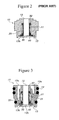
- FIG. 2 is a cross-sectional view for showing the structure of the conventional control valve for a gas cylinder
- FIG. 3 is a cross-sectional view for showing a structure of a control valve for a gas cylinder according to the present invention
- FIG. 4 is a bottom view for showing a lower surface of a pipe holder of the control valve according to the present invention.
- FIG. 5 is a cross-sectional view for showing the structure of another preferred embodiment of the present invention.
- FIG. 3 is a cross-sectional view for showing the structure of a control valve of a gas cylinder according to the present invention
- FIG. 4 is a bottom view for showing a lower surface of a pipe holder of the control valve of the present invention.
- a control valve comprises a pipe holder which has a passage 11 on the outer peripheral surface thereof, a space for engaging a structure at the inner center thereof, a pin hole 12 at an upper portion thereof, and a liner recess 13 at a lower portion thereof which has a peripheral portion corresponding to the outer diameter of a structure to be engaged inside, an inner holder 20 which is engaged with the inner central portion of the pipe holder 10 to form a passage which is communicated with the passage 11 of the pipe holder 10 , O-rings 30 which is engaged with the upper and lower sides of the inner holder 20 when the inner holder 20 is engaged with the pipe holder 10 , and a washer 40 for prevent a structure engaged with the pipe holder 10 from being deviated outside at a lower portion of the O-ring 30 provided at the lower side of the inner holder 20 .
- the peripheral portion of the extending surface formed at the central portion of the pipe holder 10 is pressed by using an exterior pressing device from a liner recess formed at the lower portion of the pipe holder 10 , and a plurality of embossed bosses 13 b are pressed at the lower portion of the washer to fix the lower side.
- a recess 10 a is formed along the upper central portion of the pipe holder 10 to reduce the weight of the injection molded pipe holder 10 .
- a rubber ring 14 is provided to seal the outer surface of the pipe holder 10 , and a penetrating passage 21 of the pipe holder 10 is connected to the passage 11 .
- the plurality of bosses 13 b are formed at the lower portion of the engaged position of the washer 40 , i.e., on the extending line of the liner recess 13 to fix the washer 40 .
- the extending portion of the liner recess 13 formed on the lower surface of the injection molded pipe holder 10 is pressed to the lower side of the washer 40 by an exterior pressing device after the inner holder 20 , the O-ring 30 , and the washer 40 is engaged in the pipe holder 10 . Then, the embossed bosses 13 b are plurally formed.
- the extending portion of the liner recess 13 i.e., the boss 13 b formed on the hill portion fixes the washer. Since the bosses 13 b are formed at a predetermined interval, the bosses 13 b slides through a space of the boss 13 b and pressed on the lower surface of the washer 40 .
- the washer 40 is pressed at the positions of the bosses 13 b and the engagement is firmly accomplished.
- the recess 10 a is formed along the peripheral portion to the central portion of the pipe holder 10 , the weight of the control valve is reduced and thus the manufacturing cost is reduced.
- FIG. 5 is a view for showing another preferred embodiment of the present invention.
- a fusion boss portion is formed at the lower end portion of the washer adhered to an inner space of the pipe holder to which the washer is engaged.
- the pipe holder is directly fused to the washer by using a ultrasonic fusing device.
- a fusing boss 40 a is formed on the upper end surface of the washer 40 of the position corresponding to the inner surface A of the pipe holder 10 adhered to the washer 40 .
- the ultrasonic fusing process is directly processed in the washer 40 , and the fusing boss 40 a is melt to be fused to the inner surface A of the pipe holder 10 .
- the fusing portion is not exposed to the outer surface of the pipe holder 10 , and the manufacturing process is simplified.
- a fusing boss 40 a is formed by using a plastic washer 30 , and the fusing boss 40 a can be formed along the upper surface peripheral portion of the washer 40 and a plurality of embossed bosses can be formed.
- the shape of the control valve is excellent and an engaging portion can be uniformly formed along the front surface of the washer.
- the fusing boss portion is formed at the upper end of the washer and the ultrasonic fusing process is directly processed in the washer to be fused on the adhering surface of the washer in the pipe holder, the manufacturing process is simple and the fusing portion is not exposed.
- the synthetic resin of the pipe holder is injection molded without any turning, it can be mass-produced and the manufacturing cost of the material is reduced.
Abstract
Description
Claims (3)
Priority Applications (1)
| Application Number | Priority Date | Filing Date | Title |
|---|---|---|---|
| US09/775,679 US6367657B1 (en) | 2001-02-05 | 2001-02-05 | Control valve for a gas cylinder |
Applications Claiming Priority (1)
| Application Number | Priority Date | Filing Date | Title |
|---|---|---|---|
| US09/775,679 US6367657B1 (en) | 2001-02-05 | 2001-02-05 | Control valve for a gas cylinder |
Publications (1)
| Publication Number | Publication Date |
|---|---|
| US6367657B1 true US6367657B1 (en) | 2002-04-09 |
Family
ID=25105158
Family Applications (1)
| Application Number | Title | Priority Date | Filing Date |
|---|---|---|---|
| US09/775,679 Expired - Lifetime US6367657B1 (en) | 2001-02-05 | 2001-02-05 | Control valve for a gas cylinder |
Country Status (1)
| Country | Link |
|---|---|
| US (1) | US6367657B1 (en) |
Citations (6)
| Publication number | Priority date | Publication date | Assignee | Title |
|---|---|---|---|---|
| US3825221A (en) * | 1972-10-30 | 1974-07-23 | Smitherm Industries | Valves for roasting apparatus and other applications |
| US4336919A (en) * | 1979-09-26 | 1982-06-29 | Lake & Elliot Incorporated | Ball valve |
| US4340204A (en) * | 1976-02-06 | 1982-07-20 | Smith International, Inc. | High pressure gate valve with preloaded, stacked, solid lubricated stem seals |
| US5178363A (en) * | 1990-11-15 | 1993-01-12 | M&Fc Holding Company, Inc. | Valve stem sealing means for prevention of fugitive emissions |
| US5755269A (en) * | 1993-12-09 | 1998-05-26 | Ciba Corning Diagnostics Corp. | Fluid delivery system |
| US6073972A (en) * | 1998-05-19 | 2000-06-13 | Emhart Inc. | Composite body faucet connection |
-
2001
- 2001-02-05 US US09/775,679 patent/US6367657B1/en not_active Expired - Lifetime
Patent Citations (6)
| Publication number | Priority date | Publication date | Assignee | Title |
|---|---|---|---|---|
| US3825221A (en) * | 1972-10-30 | 1974-07-23 | Smitherm Industries | Valves for roasting apparatus and other applications |
| US4340204A (en) * | 1976-02-06 | 1982-07-20 | Smith International, Inc. | High pressure gate valve with preloaded, stacked, solid lubricated stem seals |
| US4336919A (en) * | 1979-09-26 | 1982-06-29 | Lake & Elliot Incorporated | Ball valve |
| US5178363A (en) * | 1990-11-15 | 1993-01-12 | M&Fc Holding Company, Inc. | Valve stem sealing means for prevention of fugitive emissions |
| US5755269A (en) * | 1993-12-09 | 1998-05-26 | Ciba Corning Diagnostics Corp. | Fluid delivery system |
| US6073972A (en) * | 1998-05-19 | 2000-06-13 | Emhart Inc. | Composite body faucet connection |
Similar Documents
| Publication | Publication Date | Title |
|---|---|---|
| US9057184B2 (en) | Insulator base for electronic faucet | |
| CN108227341B (en) | IR blocking lens holder | |
| US9333698B2 (en) | Faucet base ring | |
| US4760861A (en) | Faucet manifold | |
| CN100400898C (en) | Clip | |
| US6367657B1 (en) | Control valve for a gas cylinder | |
| JP2003276457A (en) | Connector for fuel tank | |
| EP1157800A1 (en) | Method for joining synthetic resin to metallic plate | |
| EP2003007B1 (en) | Connector for fuel tank | |
| US6739749B2 (en) | Thermometric nursing bottle | |
| US11851858B2 (en) | Pull-out head integrated waterway structure | |
| AU683986B2 (en) | Method of fabricating a tank and method of fabricating a tank connector therefore | |
| KR100352503B1 (en) | Panel for electric or electronic devices and injection molding apparatus for manufacturing the panel | |
| US6358343B1 (en) | Method for manufacturing plastic drums | |
| CN220293397U (en) | Multidirectional screwed cup | |
| KR200402659Y1 (en) | having shape of the fruit of romance | |
| KR200313044Y1 (en) | Barrel of Sprayer | |
| KR100445963B1 (en) | Solenoid valve | |
| JP4273469B2 (en) | Radiator cap | |
| CN108324101B (en) | Spout assembly for electric kettle | |
| KR200312416Y1 (en) | Sealing device connected to an injection port of a vinyl pack for an infusion solution | |
| EP2024270B1 (en) | Method for manufacturing water bottle mounting supplier | |
| CN216952081U (en) | Combined groove sealing mechanism | |
| JP2007083633A (en) | Manufacturing method of fuel tank | |
| KR100225051B1 (en) | Spray container |
Legal Events
| Date | Code | Title | Description |
|---|---|---|---|
| AS | Assignment |
Owner name: SAMHONGSA, CO., LTD., KOREA, REPUBLIC OF Free format text: ASSIGNMENT OF ASSIGNORS INTEREST;ASSIGNOR:YOON, YOUNG-KI;REEL/FRAME:011823/0681 Effective date: 20010517 |
|
| STCF | Information on status: patent grant |
Free format text: PATENTED CASE |
|
| FEPP | Fee payment procedure |
Free format text: PAYOR NUMBER ASSIGNED (ORIGINAL EVENT CODE: ASPN); ENTITY STATUS OF PATENT OWNER: SMALL ENTITY |
|
| REMI | Maintenance fee reminder mailed | ||
| REFU | Refund |
Free format text: REFUND - SURCHARGE FOR LATE PAYMENT, LARGE ENTITY (ORIGINAL EVENT CODE: R1554); ENTITY STATUS OF PATENT OWNER: SMALL ENTITY |
|
| FEPP | Fee payment procedure |
Free format text: PAT HOLDER CLAIMS SMALL ENTITY STATUS, ENTITY STATUS SET TO SMALL (ORIGINAL EVENT CODE: LTOS); ENTITY STATUS OF PATENT OWNER: SMALL ENTITY |
|
| FPAY | Fee payment |
Year of fee payment: 4 |
|
| SULP | Surcharge for late payment | ||
| FPAY | Fee payment |
Year of fee payment: 8 |
|
| FEPP | Fee payment procedure |
Free format text: PAYER NUMBER DE-ASSIGNED (ORIGINAL EVENT CODE: RMPN); ENTITY STATUS OF PATENT OWNER: SMALL ENTITY Free format text: PAYOR NUMBER ASSIGNED (ORIGINAL EVENT CODE: ASPN); ENTITY STATUS OF PATENT OWNER: SMALL ENTITY |
|
| FPAY | Fee payment |
Year of fee payment: 12 |