EP0656446A2 - Ramming protection - Google Patents
Ramming protection Download PDFInfo
- Publication number
- EP0656446A2 EP0656446A2 EP94118851A EP94118851A EP0656446A2 EP 0656446 A2 EP0656446 A2 EP 0656446A2 EP 94118851 A EP94118851 A EP 94118851A EP 94118851 A EP94118851 A EP 94118851A EP 0656446 A2 EP0656446 A2 EP 0656446A2
- Authority
- EP
- European Patent Office
- Prior art keywords
- protection
- concrete core
- wall
- concrete
- crash protection
- Prior art date
- Legal status (The legal status is an assumption and is not a legal conclusion. Google has not performed a legal analysis and makes no representation as to the accuracy of the status listed.)
- Withdrawn
Links
Images


Classifications
-
- E—FIXED CONSTRUCTIONS
- E04—BUILDING
- E04F—FINISHING WORK ON BUILDINGS, e.g. STAIRS, FLOORS
- E04F19/00—Other details of constructional parts for finishing work on buildings
- E04F19/02—Borders; Finishing strips, e.g. beadings; Light coves
- E04F19/04—Borders; Finishing strips, e.g. beadings; Light coves for use between floor or ceiling and wall, e.g. skirtings
- E04F19/045—Hygienic or watertight plinths
-
- E—FIXED CONSTRUCTIONS
- E04—BUILDING
- E04F—FINISHING WORK ON BUILDINGS, e.g. STAIRS, FLOORS
- E04F19/00—Other details of constructional parts for finishing work on buildings
- E04F19/02—Borders; Finishing strips, e.g. beadings; Light coves
- E04F19/026—Borders; Finishing strips, e.g. beadings; Light coves specially adapted for cushioning impacts
Definitions
- the invention relates to a ram protection according to the preamble of claim 1, in particular the invention relates to a stable ram protection for walls in factory rooms or the like, which is easy to manufacture and has a high wear resistance.
- crash guards are in the lower area of walls, i.e. installed near the floor in factory rooms to prevent industrial trucks such as forklift trucks from damaging its walls when driving into the factory room. Furthermore, these ram guards are used to prevent damage to the forklift truck itself by protruding from the walls, so that only the intended parts of the forklift truck can ram against it.
- Ram protections of this type are conventionally cast on concrete at a height of approximately 250 mm from the finished floor on sloping concrete, with special formwork panels or boards being used.
- the concrete is coated with a concrete protective paint after it has hardened, which also enables easy cleaning of the bumper guards by forming a smooth surface.
- corner protection rails made of CNS or the like are attached to the corners of the impact protection devices in order to prevent the corners from breaking out when a forklift runs against the impact protection device.
- a device for protecting edges of beams, racks or the like is from German utility model No. 86 17 361. against mechanical damage, in particular from shelf corners against damage from industrial trucks, which is fastened as a lane boundary in front of the edge on the floor of the lane and has a metallic base plate to which an angled metallic protective plate is welded at a predetermined angle.
- this known device also reliably protects the endangered edges against damage, it has the disadvantage that its production is relatively complex due to the necessary welding work on the base plate, mudguard and possibly additional stiffeners.
- the invention is therefore based on the object of creating a stable ram protection which is easy to produce and at the same time has high wear resistance.
- a crash protection that can be attached to the floor of factory rooms to protect the walls has a jacket part made of metal, preferably stainless steel, which is anchored to the concrete core of the crash protection and forms the resilient surface of the crash protection, while at the same time serving to produce the concrete core, since it is a part the formwork when pouring the concrete core.
- the surface of the ramming protection or damage to the concrete core is prevented according to the invention, so that the ramming protection takes account of the high requirements as a deflecting element (forklift transport, trolleys, pallets, etc.) can.
- the ram protection also has a durable, smooth surface due to the jacket part, which is easy to clean, which means that even strict hygiene requirements can be met.
- the combination according to the invention of the casing part and the concrete core thus combines the overall advantage of a hard, extremely resistant to abrasion, hygienically perfect outer surface with the advantage that concrete can absorb very strong impact impacts, with deformation of the casing part being practically excluded.
- the upper and lower in the installed state of the crash protection in relation to the factory space are angled in such a way that they form undercuts, or other anchoring plates extending into the concrete core are attached to the ends of the casing can.
- filling parts made of a hard foam can be provided on or in the concrete core, which significantly reduce the weight of the impact protection and thus, for example, facilitate the installation of the impact protection.
- the upper part of the casing part is suspended in a Z-shaped profile fastened to the wall with play, while the lower end of the casing part is spaced apart from the wall by at least one spacer and possibly a spacer assigned to it. so that on-site tolerances can be compensated for before the ram protection is filled with concrete. This means that, for example on uneven walls, ram guards can be produced on-site, which themselves form a flat, resilient surface.
- At least one tube made of preferably stainless steel is attached to the casing part, which serves sanitary or wiring purposes and extends into the concrete core.
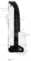
- the crash guards shown in FIGS. 1 and 2 according to the first and second preferred exemplary embodiment of the invention which are arranged at the angle between a wall 1 and a floor 2 of a factory room, have a core 3 which is cast from concrete, optionally mixed with suitable fillers and an anchored to this jacket part 4 made of stainless steel or the like, which on the one hand forms a resilient surface of the impact protection and on the other hand serves as part of the formwork for casting the concrete core 3.
- the concrete core 3 has a foot part 5, which stands on the raw or finished floor 2a, 2b of the factory space or can be fastened to it, as will be explained in more detail below.
- the impact protection has on its side facing the wall 1 or in the interior of the concrete core 3 optionally a filler 6 made of a hard foam such as polystyrene foam, which can also serve as part of the formwork for casting the concrete core 3 and reduces the weight of the impact protection.
- a filler 6 made of a hard foam such as polystyrene foam, which can also serve as part of the formwork for casting the concrete core 3 and reduces the weight of the impact protection.
- the impact protection constructed in this way can, as will be explained with reference to FIGS. 4A to 6, be prefabricated in modules as a finished part, which is then installed at the construction site.
- the jacket part 4 made as a profiled sheet has a convex shape, i.e. it is arched into the factory area when the ram protection is installed.
- the casing part 4 is angled inwards or outwards twice, the angled ends 7, 8 being formed as undercuts which the casing part 4 when the concrete core 3 is poured on Anchor the concrete core 3.
- a strip 9 of a soft foam such as neoprene is inserted or glued in the longitudinal extension of the ram protection, the relative movements and / or relative expansions between the Shells part 4 and the concrete core 3 compensates and serves for insulation purposes.
- the foot part 5 of the concrete core 3 is of anchor-shaped cross section according to FIG. 1 and can be stiffened with a correspondingly shaped steel reinforcement 10 which extends up to the upper end of the impact protection, i.e. extends through the concrete core 3 until adjacent to the upper end 8 of the casing part 4.
- the foot part 5 of the concrete core 3 can also have a different cross section, for example a rectangular cross section.
- the filling part 6 is at its upper or lower ends with respect to the impact protection provided with suitably shaped recesses 11 which extend in the longitudinal direction of the impact protection and which fill with concrete when the concrete core 3 is poured and thus anchor the filling part 6 on the concrete core 3.
- the filler 6 can also be omitted, so that the ram protection has a solid concrete core 3.
- FIG 1 and 2 also show two different installation options for the crash guards according to the invention.
- the ram protection is placed on the wall 1 on the raw floor 2a of the factory space and then the finished floor 2b is poured, the anchor part 5 of the concrete core 3 anchoring the ramming protection.
- a layer 12 of rubber or foam rubber is then applied to the hardened finished floor 2b, which also covers the corner region 13 formed between the hardened finished floor 2b and a side surface of the concrete core 3 and extends to the lower end 7 of the casing part 4, on which it fits tightly. This prevents moisture from penetrating into the joint between the concrete core 3 and the prefabricated floor 2b when the impact protection is installed, which could damage the prefabricated floor 2b or the impact protection by capillary action of this joint and / or by changing the ambient temperature.
- the crash protection shown in FIG. 2 is fastened to the finished floor 2b.
- a plurality of wall anchors 14 are attached at a suitable distance from one another, for example by pouring, in the finished floor 2b or in the raw floor 2a, which protrude upward from the finished floor 2b with a predetermined length.
- the wall anchors 14 reach through recesses 15 provided in the concrete core 3 and the filling part 6, which are introduced during the prefabrication of the impact protection, for example by inserting appropriate cores.
- the upper ends of the wall anchors 14 are firmly connected to the ram protection by means of suitable connecting devices, for example by gluing.
- These connecting devices can then be formed by adhesive cartridges 16, which are arranged in the ends of the cutouts 15 during the prefabrication of the ram guards.
- Such an adhesive cartridge 16 consists, for example, of a plastic bag, which is preferably filled with an adhesive based on synthetic resin and is pierced by the corresponding wall anchor 14 when the ram protection device is placed on the finished floor 2b, so that the adhesive is distributed and cures.
- the prefabricated floor 2b and a lower section of the impact protection are also provided with a layer 12 of rubber or foam rubber in this installation option.
- a seal 17 is introduced, which extends along the wall 1 joint between the crash protection and wall 1 closes.
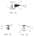
- a sealing profile 18 made of an elastic plastic is preferably used as the seal 17, as shown in FIGS. 3B and 3C, but the joint could also be grouted in a permanently elastic manner.
- the sealing profile 18 has a T-shaped upper sealing section 19 and a lower sealing and Holding section 20 on.
- the upper sealing section 19 has two sealing lips 19.1, one of which, in the installed state of the sealing profile 18 according to FIG. 2, lies sealingly against the upper end 8 of the casing part 4 and the other against the wall 1.
- the lower sealing and holding section 20 has a plurality of herringbone-like sealing and holding lips 20.1, which are set in the installation direction of the sealing profile 18 in order to clamp the sealing profile 18 by elastically spreading the sealing and holding lips 20.1 in the joint and releasing the To prevent sealing profile 18.
- the sealing and holding lips 20.1 also lie in a sealed manner in the installed state of the sealing profile 18 at the upper end 8 of the casing part 4 or on the wall 1.
- the clamping effect described can, as shown in FIG. 3C, be further reinforced by designing the lower sealing and holding section 20 as a hollow profile. Furthermore, the clamping of the sealing profile 18 in the joint can be further improved in that the upper end 8 of the casing part 4 is angled so that in the installed state of the impact protection the joint between the impact protection and the wall 1 tapers upwards.
- FIG. 3A shows an advantageous embodiment of the upper end 8 of the casing part 4, the end 8 for receiving the sealing profile 18 being of hook-shaped cross section.
- the joint for receiving the sealing profile 18 tapers.
- the end face of the upper end 8 of the jacket part 4 facing the wall 1 in the installed state of the impact protection is on the wall 1 or is at a small distance from the wall 1, so that the sealing lips 19.1 of the upper sealing section 19 of the sealing profile 18 can rest against the wall 1 or the outer surface of the casing part 4.
- the jacket part 4 consists of several sections 4.1 to 4.3, for example joined by welding, the joined ends of which are cut or bent in such a way that an inner corner or an outer corner is made of metal, which, as with reference to FIG 1 and 2 described, serves as part of the formwork when casting the concrete core 3 and forms a smooth and resistant outer surface in the prefabricated state of the impact protection module.
- 6 shows a double profile module of the crash protection according to the invention, which delimits a sandwich wall 1 downwards or carries it by means of a receiving groove 21 and has a jacket part 4 (4.4 and 4.5) on both sides of the wall 1.
- the receiving groove 21, like the cutouts 15 for fastening the ram protection, can be produced by inserting removable cores when the concrete core 3 is poured. Furthermore, in combination with the inner and outer corner modules shown in FIGS. 4A to 5B, corner modules with a double profile, ie with two opposite jacket parts, can be produced, so that the Walls of factory rooms built in sandwich construction can be completely provided with a ram protection.
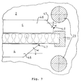
- FIG. 7 shows the completion of the impact protection according to the invention using the example of the closing situation on a door frame 22, a bollard 23 made of stainless steel and / or concrete being provided on both sides of the door frame 22 in order to prevent damage to the door frame 22.
- a first variant is shown, according to which the jacket part 4 of the impact protection module consists of three sections 4.6, 4.7 and 4.8, while the lower part of FIG. 7 shows a second variant, according to which the jacket part 4 of the impact protection module consists of two sections 4.6 and 4.7.
- the sections 4.6 of the casing parts 4 of these crash protection modules correspond in cross section to the casing parts 4 described with reference to FIGS. 1 and 2.
- the sections 4.7 and 4.8 are formed by flat metal or stainless steel plates which are welded to the sections 4.6, wherein the flat sections 4.7 form an angle ⁇ of preferably 40 ° with the wall 1 and the flat section 4.8 of the first variant extends in a substantially perpendicular direction to the wall 1.
- the ram guards described with reference to FIGS. 1 and 2 have in common that they can be brought to the construction site as prefabricated finished parts, where they are then installed. Depending on the on-site requirements, it may be necessary to pour concrete into the ram protection at the construction site. This can be particularly appropriate if the walls are uneven, so that smaller tolerances have to be compensated for at the construction site.
- the existing factory layout can also have areas that require a special adaptation of the impact protection to the on-site conditions.
- the ramming protection according to the third exemplary embodiment is arranged at the angle between the wall 1 and the floor 2 of the factory space and in the finished state has a core 3 cast from concrete and a jacket part 4 anchored to it Metal, preferably stainless steel.
- the jacket part 4 of the third exemplary embodiment shown individually in FIG.
- jacket part 10 differs from the jacket part described above essentially in that it is provided on its upper end face 24 with a preferably circular opening 25 which serves to fill the ramming protection with concrete and then with a cover made of stainless steel (not shown) is welded closed or closed with a plastic cover (not shown) which is flush with the upper end face 24.
- the metal forming the jacket part 4 is not continuously curved as in the case of FIGS. 1 and 2, but rather only over a relatively short area, so that a curved area 26 with a radius of curvature of approximately 60 adjoins the essentially flat upper end face 24 mm connects, to which a lateral end face 27 connects, which is also essentially flat.
- anchoring plates 28 are welded or screwed to the jacket part 4 directly adjacent to the upper end 8 of the jacket part 4 or directly at the angled lower end 7 of the jacket part 4.
- the ends of the anchoring plates 28 protruding into the concrete core 3 are angled in a zigzag shape in order to ensure a form-fitting fixing of the casing part 4 on the concrete core 3.
- the anchoring plates 28 are approximately 20 mm wide strips of sheet metal, preferably made of stainless steel, which are arranged in succession in the longitudinal direction of the impact protection at a distance of approximately 500 mm.
- a separating mat 30 is first made of foam, for example, which is about 5 mm thick and serves to separate wall 1 and impact protection.
- the separating mat 30 is preferably glued to the wall 1 with a suitable adhesive.
- a Z-shaped profile 31 is screwed onto the wall 1 provided with the separating mat 30, which runs essentially continuously in the longitudinal direction of the impact protection and serves to fasten the upper end 8 of the casing part 4 to the wall 1.
- the Z-shaped profile 31 is angled in such a way that it protrudes like a hook from the wall 1, at a height which essentially corresponds to the height of the finished crash protection.
- the simply angled downward in the drawing upper end 8 of the jacket part 4 can thus be hooked into the upwardly open profile 31, wherein an end section of the profile 31 extending parallel to the wall 1 is spaced apart from the wall 1 by an amount which is greater than the sheet thickness of the jacket part 4, so that smaller tolerances on site can be compensated for.
- spacers 32 are welded or screwed to the simply angled lower end 7 of the jacket part 4 in the longitudinal extension direction of the jacket part 4 at a suitable distance (for example every 500 mm) and, if necessary, screwed to the wall 1 to compensate for tolerances, so that the partition mat 30 is located between the spacer 32 or the spacer 33 and the wall 1.
- the spacer 32 is a sheet metal strip, preferably made of stainless steel, which is approximately 25 mm wide and bent in an L-shape, the end of the spacer 32 connected to the angled lower end 7 of the jacket part 4 being bent again by approximately 15 °, so that it can lie flush against the lower end 7 of the jacket part 4.
- the casing part 4 is fastened to the wall 1 in such a way that the lower end 7 of the casing part 4 is spaced from the floor 2 (in the case shown a sloping concrete floor) by about 70 to 80 mm and the lateral end face 27 is essentially parallel to the wall 1 extends.
- a device 50 consists of three rectangular metal profiles 51 welded into a right-angled triangle, of which the metal profile 51 forming the hypotenuse extends beyond the triangle and is provided with an adjusting foot 52 at its end.
- the leveling foot 52 consists of a threaded bolt 53 which is welded to the metal profile 51 Threaded bushing 54 is screwed in and, at its end facing the jacket part 4, has a section 55 which is enlarged in diameter compared to the diameter of the threaded bolt 53 and which forms a positioning surface which comes into engagement with the upper end face 24 of the jacket part 4.
- the metal profiles 51 forming the right angle are provided on their end faces facing the bottom 2 or the wall 1, each with two perforated tabs 56, which serve to fasten the device 50 to the bottom 2 or with one flush with the lateral end face 27 of the Shell part 4 adjacent formwork board 57 are screwed from a waterproof plywood.
- the formwork board 57 is screwed below the lower end 7 of the casing part 4 to a plastic board 58 made of, for example, Nierolen® and extending along the casing part 4, on the lower edge of which a sealing lip 59 made of soft PVC is attached, which is bent in the switched-on state of the jacket part 4 in the direction of the wall 1 in order to prevent concrete from flowing out.
- a gasket 60 made of foam rubber is inserted between the formwork board 57, which ends flush in the direction of the floor 2 with the vertical metal profile 51, and the floor 2, which additionally seals the formwork to the outside.
- the seal 60 which is circular in cross section in the unloaded state, has a diameter which is at least twice as large as the thickness of the lower tabs 56, which space the device 50 from the base 2.
- the device 50 fastened to the floor 2 thus seals the ramming protection from the outside via the sealing lip 59 and the seal 60 and holds the casing part 4 in its predetermined position, the formwork board 57 being the parallel position of the lateral end face 27 of the jacket part 4 with respect to the wall 1, while the adjustable foot 52 prevents that the upper end face 24 of the casing part 4 can move upwards.
- the impact protection is filled with concrete 3 through the openings 25 in the upper end face 24 of the casing part 4.
- the concrete used preferably B10 - B15
- the concrete used is mixed with a retarder and a foaming agent.
- the impact protection complete i.e. Filled with concrete up to close to the inside of the casing part 4 facing away from the upper end face 24, and the concrete was able to set for about 24 hours
- the ram protection is switched off, for which purpose the device 50 consisting of parts 51 to 60 is removed from the ramming protection.
- the jacket part 4 is now reliably fixed via the angled ends 7 and 8 acting as undercuts and the anchoring plates 28 on the concrete core 3 and forms the resilient surface of the impact protection without this being able to separate from the concrete core 3.
- the sloping concrete floor 2 can be provided with a plastic floor, which adjoins the lower end 7 of the casing part 4 with a fillet 61 (shown in broken lines in FIG. 8).
- a fillet 61 shown in broken lines in FIG. 8
- the part of the separating mat 30 projecting upward above the ram protection is cut off and the gap 34 extending between the upper end 8 of the casing part 4 and the wall 1 and extending up to the Z-shaped profile 31 groomed.
- a band or cord 35 made of a suitable fabric is first inserted into the base of the joint 34 formed by the Z-shaped profile 31, which extends along the ram protection.
- the joint 34 is then finished with silicone 36.
- the cord 35 is provided so that the silicone 36 through Pulling out the cord 35 can be easily removed from the joint 34 if the joint 34 is to be newly grouted, for example for hygiene reasons.
- the openings 25 in the upper end face 24 of the casing part 4 are welded closed by means of suitably shaped lids (not shown) and the weld seams are treated in such a way that the upper end face 24 is smooth and flat.
- the ram protection according to the third exemplary embodiment of the invention is particularly suitable for “made-to-measure” items, for example on uneven walls, since smaller on-site tolerances can be compensated for via the Z-shaped profile 31 or the spacers 32 and spacers 33, the ramming protection via the jacket part 4 forms a flat, resilient surface which extends essentially parallel to the wall 1.
- the jacket part 4 serves as part of the formwork, so that the manufacture of the impact protection is simplified.
- sanitary pipes 37 preferably made of stainless steel, can be welded to the jacket part 4, thereby making sanitary installations and / or electrical installations in the ram protection before pouring the ramming protection with concrete.
- This is particularly advantageous if pipes or lines are to be retrofitted with appropriate planning, since pipes and lines can be retrofitted in the impact protection without the walls having to be opened.
- Such internals, which are attached to the casing part 4, can equally be provided in the first to third exemplary embodiments.
- a ram protection is proposed, which can be arranged between a wall 1 and a floor 2 of a factory space, and has a core 3 cast from concrete and an anchored part 4 made of stainless steel or the like.
- this jacket part 4 forms a resilient surface of the impact protection and, on the other hand, serves as part of the formwork for casting the concrete core 3.
- it is characterized by good wear resistance.
Abstract
Description
Die Erfindung bezieht sich auf einen Rammschutz gemäß dem Oberbegriff des Patentanspruchs 1, insbesondere bezieht sich die Erfindung auf einen stabilen Rammschutz für Wände in Fabrikräumen oder dergleichen, der leicht herzustellen ist und eine hohe Verschleißbeständigkeit aufweist.The invention relates to a ram protection according to the preamble of
Derartige Rammschutze werden im unteren Bereich von Wänden, d.h. nahe dem Boden in Fabrikräumen angebracht, um zu verhindern, daß Flurförderzeuge wie beispielsweise Gapelstapler beim Befahren des Fabrikraums dessen Wände durch Anrammen beschädigen. Ferner werden diese Rammschutze dazu verwendet, eine Beschädigung der Gabelstapler selbst zu verhindern, indem die Rammschutze von den Wänden vorstehen, so daß nur dafür vorgesehene Teile der Gabelstapler anrammen können.Such crash guards are in the lower area of walls, i.e. installed near the floor in factory rooms to prevent industrial trucks such as forklift trucks from damaging its walls when driving into the factory room. Furthermore, these ram guards are used to prevent damage to the forklift truck itself by protruding from the walls, so that only the intended parts of the forklift truck can ram against it.
Rammschutze dieser Gattung werden herkömmlicherweise am Bau aus Beton in einer Höhe von etwa 250 mm ab Fertigfußboden auf Gefällebeton gegossen, wobei spezielle Schalungsplatten bzw. -bretter Anwendung finden. Zum Schutz der gegossenen Rammschutze wird der Beton nach dem Aushärten mit einer Betonschutzfarbe angestrichen, die durch Ausbildung einer glatten Oberfläche auch eine leichte Reinigung der Rammschutze ermöglicht. Ferner werden an den Ecken der Rammschutze Eckschutzschienen aus CNS oder dergleichen angebracht, um ein Ausbrechen der Ecken zu verhindern, wenn ein Gabelstapler gegen den Rammschutz fährt.Ram protections of this type are conventionally cast on concrete at a height of approximately 250 mm from the finished floor on sloping concrete, with special formwork panels or boards being used. To protect the cast bumper guards, the concrete is coated with a concrete protective paint after it has hardened, which also enables easy cleaning of the bumper guards by forming a smooth surface. Furthermore, corner protection rails made of CNS or the like are attached to the corners of the impact protection devices in order to prevent the corners from breaking out when a forklift runs against the impact protection device.
Obgleich die herkömmlichen Rammschutze die Wände der Fabrikräume zuverlässig gegen Beschädigungen schützen, weist dieser Stand der Technik den Nachteil auf, daß die Herstellung der Rammschutze relativ aufwendig ist, weil zuerst eine Schalung gebaut wird, die nach dem Vergießen des Betons wieder entfernt werden muß. Ferner hat die relativ weiche Oberflache der Rammschutze im robusten Fabrikbetrieb schnell starke Verschleißerscheinungen, so daß die Rammschutze oft ausgebessert und nachgestrichen werden müssen, um eine glatte und gut zu reinigende Oberfläche dauerhaft zu gewährleisten. Dies ist insbesondere bei Produktionsstätten in der Lebensmittelindustrie oder dergleichen kritisch zu beurteilen, da dort hohe Hygieneanforderungen zu erfüllen sind und dementsprechend ein dauerhaftes Verschmutzen der Rammschutze mit vernünftigem Aufwand unbedingt vermieden werden muß. In diesem Zusammenhang ist auch die herstellungsbedingte Rauhigkeit und Ungenauigkeit der Anschlußfugen der Rammschutze als unbefriedigend zu bewerten, da sich dort Schmutz festsetzt, der entweder gar nicht oder nur mit großem Aufwand wieder entfernt werden kann.Although the conventional ram guards reliably protect the walls of the factory rooms against damage, this prior art has the disadvantage that the manufacture of the ram guards is relatively complex because first a formwork is built which has to be removed again after the concrete has been poured. Furthermore, it has relative Soft surface of the ram guards in robust factory operation quickly shows strong signs of wear, so that the ram guards often have to be repaired and repainted to ensure a smooth, easy-to-clean surface. This is to be assessed critically, in particular in the case of production sites in the food industry or the like, since there are high hygiene requirements to be met and, accordingly, permanent contamination of the bumper guards must be avoided with reasonable effort. In this connection, the roughness and inaccuracy of the connection joints of the ram guards due to the manufacturing process are to be assessed as unsatisfactory, since dirt settles there, which either cannot be removed at all or can only be removed with great effort.
Desweiteren ist aus dem deutschen Gebrauchsmuster Nr. 86 17 361 eine Vorrichtung zum Schützen von Kanten von Trägern, Gestellen o.ä. vor mechanischer Beschädigung, insbesondere von Regalecken gegen Beschädigung durch Flurförderer bekannt, die als Fahrbahnbegrenzung vor der Kante auf dem Fahrbahnboden befestigt wird und eine metallische Grundplatte aufweist, an der ein abgewinkeltes metallisches Schutzblech unter einem vorbestimmten Winkel angeschweißt ist. Obgleich auch diese vorbekannte Vorrichtung die gefährdeten Kanten zuverlässig gegen Beschädigungen schützt, weist sie den Nachteil auf, daß ihre Herstellung bedingt durch die notwendigen Schweißarbeiten an Grundplatte, Schutzblech und gegebenenfalls zusätzlichen Versteifungen relativ aufwendig ist.Furthermore, a device for protecting edges of beams, racks or the like is from German utility model No. 86 17 361. against mechanical damage, in particular from shelf corners against damage from industrial trucks, which is fastened as a lane boundary in front of the edge on the floor of the lane and has a metallic base plate to which an angled metallic protective plate is welded at a predetermined angle. Although this known device also reliably protects the endangered edges against damage, it has the disadvantage that its production is relatively complex due to the necessary welding work on the base plate, mudguard and possibly additional stiffeners.
Gegenüber dem eingangs genannten Stand der Technik liegt der Erfindung daher die Aufgabe zugrunde, einen stabilen Rammschutz zu schaffen, der leicht herzustellen ist und gleichzeitig eine hohe Verschleißbeständigkeit aufweist.Compared to the prior art mentioned at the outset, the invention is therefore based on the object of creating a stable ram protection which is easy to produce and at the same time has high wear resistance.
Diese Aufgabe wird durch die im Patentanspruch 1 angegebenen Merkmale gelöst.This object is achieved by the features specified in
Erfindungsgemäß hat ein am Boden von Fabrikräumen befestigbarer Rammschutz zum Schutz der Wände ein Mantelteil aus Metall, vorzugsweise aus Edelstahl, das am Betonkern des Rammschutzes verankert ist und die belastbare Oberfläche des Rammschutzes ausbildet, wobei es gleichzeitig der Herstellung des Betonkerns dient, da es einen Teil der Schalung beim Gießen des Betonkerns ausbildet. Somit lassen sich leicht fertige Rammschutzelemente vorfertigen, die am Bau in dem Fabrikraum eingebaut werden können, wobei die Schalung am Bau entfällt, bzw. die Rammschutze lassen sich bauseits leichter herstellen, da das Mantelteil der Rammschutze bereits als Teil der Schalung dient.According to the invention, a crash protection that can be attached to the floor of factory rooms to protect the walls has a jacket part made of metal, preferably stainless steel, which is anchored to the concrete core of the crash protection and forms the resilient surface of the crash protection, while at the same time serving to produce the concrete core, since it is a part the formwork when pouring the concrete core. This makes it easy to prefabricate ram protection elements that can be installed on site in the factory, eliminating the need for formwork on site, or the ram guards can be manufactured more easily on site, since the shell part of the ram protection already serves as part of the formwork.
Durch die langlebige, harte, vorzugsweise aus Edelstahl bestehende Anprallfläche des Rammschutzes wird erfindungsgemäß ein Abtragen der Oberfläche des Rammschutzes bzw. eine Beschädigung des Betonkerns verhindert, so daß der Rammschutz den hohen Anforderungen als Abweiseelement (Gabelstaplerverkehr, Transportwagen, Paletten, etc.) Rechnung tragen kann. Der Rammschutz weist durch das Mantelteil ebenso eine beständige, glatte Oberfläche auf, die leicht zu reinigen ist, wodurch auch strengen Hygieneerfordernissen entsprochen werden kann. Neben herstellungstechnischen Vorteilen, verbindet die erfindungsgemäße Kombination aus Mantelteil und Betonkern somit insgesamt den Vorteil einer harten, gegen Abrieb außerordentlich resistenten, hygienisch einwandfreien Außenfläche mit dem Vorteil, daß Beton sehr starke Aufprallstöße aufnehmen kann, wobei eine Verformung des Mantelteils praktisch ausgeschlossen ist.Due to the long-lasting, hard impact surface of the ram protection, preferably made of stainless steel, the surface of the ramming protection or damage to the concrete core is prevented according to the invention, so that the ramming protection takes account of the high requirements as a deflecting element (forklift transport, trolleys, pallets, etc.) can. The ram protection also has a durable, smooth surface due to the jacket part, which is easy to clean, which means that even strict hygiene requirements can be met. In addition to advantages in terms of manufacturing technology, the combination according to the invention of the casing part and the concrete core thus combines the overall advantage of a hard, extremely resistant to abrasion, hygienically perfect outer surface with the advantage that concrete can absorb very strong impact impacts, with deformation of the casing part being practically excluded.
Dadurch, daß gemäß Anspruch 2 die im eingebauten Zustand des Rammschutzes in Bezug zum Fabrikraum oberen und unteren Enden des Mantelteils derart abgewinkelt sind, daß sie Hinterschnitte ausbilden, bzw. weitere sich in den Betonkern hinein erstreckende Verankerungsbleche an den Enden des Mantelteils angebracht sind, ist das Mantelteil zuverlässig am Betonkern verankert, so daß selbst sehr starke Aufprallstöße das Mantelteil nicht vom Betonkern lösen können.Characterized in that according to
Gemäß der Lehre des Anspruchs 3 können am oder im Betonkern Füllteile aus einem Hartschaum vorgesehen sein, die das Gewicht des Rammschutzes deutlich reduzieren und somit beispielsweise den Einbau des Rammschutzes erleichtern.According to the teaching of
Gemäß dem Anspruch 5 ist das Mantelteil mit seinem oberen Ende in ein an der Wand befestigtes Z-förmiges Profil mit Spiel eingehängt ist, während das untere Ende des Mantelteils über mindestens einen Abstandshalter und ggf. ein dem zugeordnetes Distanzstück von der Wand definiert beabstandet ist, so daß vor dem Verfüllen des Rammschutzes mit Beton bauseitige Toleranzen ausgeglichen werden können. Somit lassen sich bei beispielsweise unebenen Wänden Rammschutze bauseits herstellen, die selbst eine ebene belastbare Oberfläche ausbilden.According to
Gemäß der Lehre des Anspruchs 7 ist an das Mantelteil mindestens ein Rohr aus vorzugsweise Edelstahl angebracht, das Sanitär- oder Verkabelungszwecken dient und sich in den Betonkern hinein erstreckt. Somit können bei entsprechender Planung auf vorteilhafte Weise nachträglich Rohre oder Leitungen in den Rammschutzen verlegt werden, ohne daß die Wände dazu aufgeschlagen werden müßten.According to the teaching of
Weitere vorteilhafte Ausgestaltungen der Erfindung sind Gegenstand der übrigen Unteransprüche.Further advantageous embodiments of the invention are the subject of the remaining subclaims.
Die Erfindung wird nachstehend anhand von bevorzugten Ausführungsbeispielen unter Bezugnahme auf die Zeichnung näher erläutert, wobei gleiche oder ähnliche Teile mit gleichen Bezugszahlen versehen sind. Dabei zeigen:
- Die Fig. 1 eine Schnittansicht eines ersten bevorzugten Ausführungsbeispiels des erfindungsgemäßen Rammschutzes, der auf dem Rohboden eines Fabrikraums aufsteht,
- die Fig. 2 eine Schnittansicht eines zweiten bevorzugten Ausführungsbeispiels des erfindungsgemäßen Rammschutzes, der auf dem Gefällebeton eines Fabrikraums befestigt ist,
- die Fig. 3A eine Schnittansicht einer Anschlußfuge, wie sie bei dem erfindungsgemäßen Rammschutz Anwendung finden kann (Detail A in Fig. 2),
- die Fig. 3B und 3C Seitenansichten von Dichtprofilen, die in die Anschlußfuge des erfindungsgemäßen Rammschutzes eingesetzt werden können, wobei in der Fig. 3C das in der Fig. 2 im eingebauten Zustand gezeigte Dichtprofil dargestellt ist,
- die Fig. 4A und 4B eine Seitenansicht bzw. eine Draufsicht auf ein Inneneckmodul eines erfindungsgemäß ausgebildeten Rammschutzes,
- die Fig. 5A und 5B eine Seitenansicht bzw. eine Draufsicht auf ein Außeneckmodul eines erfindungsgemäß ausgebildeten Rammschutzes,
- die Fig. 6 eine Seitenansicht eines Doppelprofilmoduls eines erfindungsgemäß ausgebildeten Rammschutzes für freistehende Sandwichwände,
- die Fig. 7 eine Draufsicht auf den Abschluß bzw. ein Abschlußmodul eines erfindungsgemäß ausgebildeten Rammschutzes am Beispiel der Abschlußsituation an einer Türzarge,
- die Fig. 8 eine Schnittansicht eines dritten bevorzugten Ausführungsbeispiels des erfindungsgemäßen Rammschutzes, die auch eine Vorrichtung zur Herstellung des Rammschutzes zeigt,
- die Fig. 9 eine perspektivische Ansicht des Rammschutzes und der Vorrichtung zur Herstellung des Rammschutzes gemäß Fig. 8,
- die Fig. 10 eine Schnittansicht des Mantelteils des Rammschutzes gemäß Fig. 8, und
- die Fig. 11 eine Schnittansicht des Mantelteils des Rammschutzes gemäß Fig. 8, das zusätzlich sanitärtechnische Einbauten aufweist.
- 1 is a sectional view of a first preferred embodiment of the crash protection according to the invention, which stands on the bare floor of a factory room,
- 2 is a sectional view of a second preferred embodiment of the crash protection according to the invention, which is fastened on the sloping concrete of a factory room,
- 3A is a sectional view of a connection joint, as can be used in the impact protection according to the invention (detail A in FIG. 2),
- 3B and 3C side views of sealing profiles that can be used in the connection joint of the ram protection according to the invention, the sealing profile shown in FIG. 2 in the installed state being shown in FIG. 3C,
- 4A and 4B are a side view and a plan view of an inside corner module of a crash protection designed according to the invention,
- 5A and 5B are a side view and a plan view of an outer corner module of a crash protection designed according to the invention,
- 6 shows a side view of a double-profile module of a ram protection designed according to the invention for free-standing sandwich walls,
- 7 is a plan view of the closure or a closure module of a ram guard designed according to the invention using the example of the closure situation on a door frame,
- 8 is a sectional view of a third preferred embodiment of the crash protection according to the invention, which also shows a device for producing the crash protection,
- 9 is a perspective view of the crash protection and the device for producing the crash protection according to FIG. 8,
- 10 is a sectional view of the shell part of the crash protection according to FIG. 8, and
- FIG. 11 is a sectional view of the jacket part of the impact protection according to FIG. 8, which additionally has sanitary fittings.
Die in den Fig. 1 und 2 dargestellten Rammschutze gemäß dem ersten bzw. zweiten bevorzugten Ausführungsbeispiel der Erfindung, welche in dem Winkel zwischen einer Wand 1 und einem Boden 2 eines Fabrikraums angeordnet werden, weisen einen aus gegebenenfalls mit geeigneten Füllstoffen versetzten Beton gegossenen Kern 3 und ein an diesem verankertes Mantelteil 4 aus Edelstahl oder dergleichen auf, der zum einen eine belastbare Oberfläche des Rammschutzes ausbildet und zum anderen als Teil der Schalung zum Gießen des Betonkerns 3 dient. An seinem unteren Ende weist der Betonkern 3 einen Fußteil 5 auf, der auf dem Roh- oder Fertigboden 2a, 2b des Fabrikraums aufsteht bzw. an diesem befestigt werden kann, wie im folgenden noch näher erläutert werden soll. Ferner hat der Rammschutz an seiner der Wand 1 zugekehrten Seite bzw. im Inneren des Betonkerns 3 wahlweise ein Füllteil 6 aus einem Hartschaum wie beispielsweise Polystyrolschaum, das ebenfalls als Teil der Schalung zum Gießen des Betonkerns 3 dienen kann und das Gewicht des Rammschutzes reduziert. Der so aufgebaute Rammschutz kann, wie unter Bezugnahme auf die Fig. 4A bis 6 noch erläutert wird, modulweise als Fertigteil vorgefertigt werden, welches dann an der Baustelle eingebaut wird.The crash guards shown in FIGS. 1 and 2 according to the first and second preferred exemplary embodiment of the invention, which are arranged at the angle between a
Gemäß Fig. 1 hat das als Profilblech gefertigte Mantelteil 4 eine konvexe Form, d.h. es ist im montierten Zustand des Rammschutzes in den Fabrikraum hinein vorgewölbt. An den dem Fertigboden 2b bzw. der Wand 1 nächstgelegenen Enden 7, 8 ist das Mantelteil 4 ein- bzw. zweifach nach innen abgewinkelt, wobei die abgewinkelten Enden 7, 8 als Hinterschnitte ausgebildet sind, die das Mantelteil 4 beim Gießen des Betonkerns 3 am Betonkern 3 verankern. In das zweifach abgewinkelte untere Ende 7 des Mantelteils 4, das ein im Querschnitt im wesentlichen U-förmigen Abschluß ausbildet, ist in Längserstreckung des Rammschutzes ein Streifen 9 aus einem Weichschaum wie beispielsweise Neopren eingelegt bzw. festgeklebt, der Relativbewegungen und/oder Relativdehnungen zwischen dem Mantelteil 4 und dem Betonkern 3 ausgleicht sowie zu Isolierungszwecken dient.1, the
Der Fußteil 5 des Betonkerns 3 ist gemäß Fig. 1 im Querschnitt ankerförmig ausgebildet und kann mit einer entsprechend geformten Stahlarmierung 10 ausgesteift sein, die sich bis zum oberen Ende des Rammschutzes, d.h. bis angrenzend an das obere Ende 8 des Mantelteils 4 durch den Betonkern 3 hindurch erstreckt. Wie der Fig. 2 zu entnehmen ist, kann je nach Anwendungsfall der Fußteil 5 des Betonkerns 3 aber auch einen anderen, beispielsweise einen rechteckigen Querschnitt aufweisen.The
Ferner ist, wie in Fig. 1 dargestellt, das Füllteil 6 an seinen in Bezug zum Rammschutz oberen bzw. unteren Enden mit sich in Längsrichtung des Rammschutzes erstreckenden, geeignet geformten Aussparungen 11 versehen, die sich beim Gießen des Betonkerns 3 mit Beton füllen und somit das Füllteil 6 am Betonkern 3 verankern. Wie bereits oben ausgeführt wurde, kann das Füllteil 6 jedoch auch weggelassen werden, so daß der Rammschutz einen massiven Betonkern 3 aufweist.Furthermore, as shown in FIG. 1, the filling
Die Fig. 1 und 2 zeigen weiterhin zwei verschiedene Einbaumöglichkeiten der erfindungsgemäßen Rammschutze.1 and 2 also show two different installation options for the crash guards according to the invention.
Gemäß Fig. 1 wird der Rammschutz an die Wand 1 auf den Rohboden 2a des Fabrikraums aufgesetzt und dann der Fertigboden 2b gegossen, wobei der ankerförmig ausgebildete Fußteil 5 des Betonkerns 3 den Rammschutz verankert. Auf den ausgehärteten Fertigboden 2b wird dann eine Schicht 12 aus Gummi oder Moosgummi aufgetragen, die auch den zwischen dem ausgehärteten Fertigboden 2b und einer Seitenfläche des Betonkerns 3 ausgebildeten Eckbereich 13 überdeckt und sich bis an das untere Ende 7 des Mantelteils 4 erstreckt, an dem sie dicht anliegt. Somit wird verhindert, daß bei eingebautem Rammschutz Feuchtigkeit in die Fuge zwischen dem Betonkern 3 und dem Fertigboden 2b eindringen kann, die durch Kapillarwirkung dieser Fuge und/oder durch Änderung der Umgebungstemperatur den Fertigboden 2b bzw. den Rammschutz beschädigen könnte.1, the ram protection is placed on the
Der in Fig. 2 dargestellte Rammschutz ist im Gegensatz zu dem in Fig. 1 dargestellten Einbauzustand auf dem Fertigboden 2b befestigt. Dafür sind im Fertigboden 2b bzw. im Rohboden 2a entlang der Wand 1 eine Mehrzahl von Mauerankern 14 mit geeignetem Abstand zueinander beispielsweise durch Eingießen befestigt, die vom Fertigboden 2b mit einer vorbestimmten Länge nach oben vorstehen. Im eingebauten Zustand des Rammschutzes durchgreifen die Maueranker 14 dafür vorgesehene Aussparungen 15 im Betonkern 3 und dem Füllteil 6, welche bereits beim vorfertigen der Rammschutze beispielsweise durch Einlegen entsprechender Kerne eingebracht werden. Die oberen Enden der Maueranker 14 sind mittels geeigneter Verbindungseinrichtungen mit dem Rammschutz fest verbunden, beispielsweise durch Verkleben. Diese Verbindungseinrichtungen können dann durch Klebepatronen 16 ausgebildet werden, die beim Vorfertigen der Rammschutze in den Enden der Aussparungen 15 angeordnet werden. Eine solche Klebepatrone 16 besteht beispielsweise aus einem Plastikbeutel, der vorzugsweise mit einem Klebstoff auf Kunstharzbasis gefüllt ist und beim Aufsetzen des Rammschutzes auf den Fertigboden 2b von dem entsprechenden Maueranker 14 durchstoßen wird, so daß sich der Klebstoff verteilt und aushärtet. Schließlich wird, wie unter Bezugnahme auf die Fig. 1 bereits beschrieben wurde, auch bei dieser Einbaumöglichkeit der Fertigboden 2b und ein unterer Abschnitt des Rammschutzes mit einer Schicht 12 aus Gummi oder Moosgummi versehen.In contrast to the installation state shown in FIG. 1, the crash protection shown in FIG. 2 is fastened to the
Im folgenden wird unter Bezugnahme auf die Fig. 2 bis 3C der obere Abschluß (Detail A in Fig. 2) des Rammschutzes an der Wand 1 beschrieben.The upper end (detail A in FIG. 2) of the impact protection on the
Wie der Fig. 2 zu entnehmen ist, ist im eingebauten Zustand des Rammschutzes zwischen einer der Wand 1 zugewandten Stirnfläche des einfach abgewinkelten oberen Endes 8 des Mantelteils 4 und der Wand 1 eine Dichtung 17 eingebracht, die die sich längs der Wand 1 erstreckende Fuge zwischen dem Rammschutz und der Wand 1 schließt. Vorzugsweise wird als Dichtung 17 ein Dichtprofil 18 aus einem elastischen Kunststoff verwendet, wie es in den Figuren 3B und 3C dargestellt ist, die Fuge könnte aber auch dauerelastisch verfugt werden.As can be seen in FIG. 2, in the installed state of the crash protection between a
Gemäß den Fig. 3B und 3C weist das Dichtprofil 18 einen T-förmigen oberen Dichtabschnitt 19 und einen unteren Dicht- und Halteabschnitt 20 auf. Der obere Dichtabschnitt 19 weist zwei Dichtlippen 19.1 auf, von denen im eingebauten Zustand des Dichtprofils 18 gemäß Fig. 2 die eine am oberen Ende 8 des Mantelteils 4 und die andere an der Wand 1 dichtend anliegt. Der untere Dicht- und Halteabschnitt 20 hat eine Mehrzahl von fischgrätenartig angeordneten Dicht- und Haltelippen 20.1, die in Einbaurichtung des Dichtprofils 18 angestellt sind, um das Dichtprofil 18 durch elastisches Aufspreizen der Dicht- und Haltelippen 20.1 in der Fuge zu verklammern und ein Lösen des Dichtprofils 18 zu verhindern. Wie die Fig. 2 zeigt, liegen auch die Dicht- und Haltelippen 20.1 im eingebauten Zustand des Dichtprofils 18 am oberen Ende 8 des Mantelteils 4 bzw. an der Wand 1 dichtend an.3B and 3C, the sealing
Der beschriebene Verklammerungseffekt kann, wie in Fig. 3C dargestellt ist, durch Ausbildung des unteren Dicht- und Halteabschnitts 20 als Hohlprofil noch zusätzlich verstärkt werden. Ferner kann die Verklammerung des Dichtprofils 18 in der Fuge noch dadurch verbessert werden, daß das obere Ende 8 des Mantelteils 4 so abgewinkelt wird, daß sich im eingebauten Zustand des Rammschutzes die Fuge zwischen dem Rammschutz und der Wand 1 nach oben verjüngt.The clamping effect described can, as shown in FIG. 3C, be further reinforced by designing the lower sealing and holding
Die Fig. 3A zeigt eine vorteilhafte Ausbildung des oberen Endes 8 des Mantelteils 4, wobei das Ende 8 zur Aufnahme des Dichtprofils 18 im Querschnitt hakenförmig ausgebildet ist. Auch hier verjüngt sich, wie schon unter Bezugnahme auf die Fig. 2 beschrieben, die Fuge zur Aufnahme des Dichtprofils 18. Gemäß diesem Ausführungsbeispiel liegt die im eingebauten Zustand des Rammschutzes der Wand 1 zugewandte Stirnfläche des oberen Endes 8 des Mantelteils 4 an der Wand 1 an oder weist einen kleinen Abstand zur Wand 1 auf, so daß die Dichtlippen 19.1 des oberen Dichtabschnitts 19 des Dichtprofils 18 an der Wand 1 bzw. der Außenfläche des Mantelteils 4 anliegen können.3A shows an advantageous embodiment of the
Bisher wurde der erfindungsgemäße Rammschutz bezüglich seines Aufbaus im Querschnitt beschrieben, wobei davon ausgegangen wurde, daß sich dieser Querschnitt in Längserstreckung des Rammschutzes über eine vorbestimmte Länge fortsetzt. Somit lassen sich Längsmodule von vorbestimmter Länge vorsehen, die entlang einer Wand elementartig zusammengesetzt den Rammschutz ausbilden. Im Rahmen eines Baukastensystems sind weiterhin Inneneckmodule, Außeneckmodule, Doppelprofilmodule und Abschlußmodule vorgesehen, wie im folgenden unter Bezugnahme auf die Fig. 4A bis 7 beschrieben wird, wobei der sonstige Aufbau der Rammschutzmodule bzw. deren Einbau dem der unter Bezugnahme auf die Fig. 1 bis 3C beschriebenen Längsmodule entspricht.So far, the structure of the crash protection according to the invention has been described in cross section, it being assumed that this cross section continues in the longitudinal extent of the crash protection over a predetermined length. In this way, longitudinal modules of a predetermined length can be provided, which form the ram protection element-like along a wall. Within the framework of a modular system, inner corner modules, outer corner modules, double profile modules and end modules are also provided, as will be described below with reference to FIGS. 4A to 7, the other structure of the impact protection modules or their installation being the same as that with reference to FIGS. 1 to 3C corresponds to the longitudinal modules described.
Gemäß den Fig. 4A bis 5B besteht das Mantelteil 4 aus mehreren beispielsweise durch Schweißen zusammengefügten Abschnitten 4.1 bis 4.3, deren zusammengefügte Enden derart geschnitten bzw. gebogen ist, daß eine Innenecke bzw. eine Außenecke aus Metall entsteht, die, ebenso wie unter Bezugnahme auf die Fig. 1 und 2 beschrieben, beim Gießen des Betonkerns 3 als Teil der Schalung dient und im vorgefertigten Zustand des Rammschutzmoduls eine glatte und widerstandsfähige Außenoberfläche ausbildet. In Fig. 6 ist ein Doppelprofilmodul des erfindungsgemäßen Rammschutzes dargestellt, das eine Sandwichwand 1 nach unten begrenzt bzw. mittels einer Aufnahmenut 21 trägt und zu beiden Seiten der Wand 1 jeweils ein Mantelteil 4 (4.4 und 4.5) aufweist. Die Aufnahmenut 21 kann ebenso wie die Aussparungen 15 zur Befestigung des Rammschutzes durch Einlegen von entfernbaren Kernen beim Gießen des Betonkerns 3 hergestellt werden. Ferner lassen sich in Kombination der in den Fig. 4A bis 5B dargestellten Innen- bzw. Außeneckmodule Eckmodule mit Doppelprofil, d.h. mit zwei gegenüberliegenden Mantelteilen herstellen, so daß auch die Wände von in Sandwichbauweise aufgebauten Fabrikräumen vollständig mit einem Rammschutz versehen werden können.4A to 5B, the
Die Fig. 7 zeigt den Abschluß des erfindungsgemäßen Rammschutzes am Beispiel der Abschlußsituation an einer Türzarge 22, wobei zu beiden Seiten der Türzarge 22 jeweils ein Poller 23 aus Edelstahl und/oder Beton vorgesehen ist, um eine Beschädigung der Türzarge 22 zu verhindern. Im oberen Teil der Fig. 7 ist eine erste Variante dargestellt, gemäß der das Mantelteil 4 des Rammschutzmoduls aus drei Abschnitten 4.6, 4.7 und 4.8 besteht, während der untere Teil der Fig. 7 eine zweite Variante zeigt, gemäß der das Mantelteil 4 des Rammschutzmoduls aus zwei Abschnitten 4.6 und 4.7 besteht. Die Abschnitte 4.6 der Mantelteile 4 dieser Rammschutzmodule entsprechen im Querschnitt den unter Bezugnahme auf die Fig. 1 und 2 beschriebenen Mantelteilen 4. Die Abschnitte 4.7 und 4.8 werden hingegen von ebenen Metall- bzw. Edelstahlplatten ausgebildet, die an die Abschnitte 4.6 angeschweißt sind, wobei die ebenen Abschnitte 4.7 mit der Wand 1 einen Winkel α von vorzugsweise 40° einschließen und der ebene Abschnitt 4.8 der ersten Variante sich in im wesentlichen senkrechter Richtung zur Wand 1 erstreckt.7 shows the completion of the impact protection according to the invention using the example of the closing situation on a
Den unter Bezugnahme auf die Fig. 1 und 2 beschriebenen Rammschutzen ist gemein, daß sie als vorgefertigte Fertigteile an die Baustelle verbracht werden können, wo sie dann eingebaut werden. In Abhängigkeit von den bauseitigen Erfordernissen kann es aber notwendig sein, daß der Rammschutz vor Ort an der Baustelle mit Beton vergossen wird. Dies kann insbesondere dann angebracht sein, wenn die Wände uneben sind, so daß an der Baustelle kleinere Toleranzen auszugleichen sind. Auch kann das vorhandene Fabriklayout Bereiche aufweisen, die eine besondere Anpassung des Rammschutzes an die bauseitigen Bedingungen erfordern.The ram guards described with reference to FIGS. 1 and 2 have in common that they can be brought to the construction site as prefabricated finished parts, where they are then installed. Depending on the on-site requirements, it may be necessary to pour concrete into the ram protection at the construction site. This can be particularly appropriate if the walls are uneven, so that smaller tolerances have to be compensated for at the construction site. The existing factory layout can also have areas that require a special adaptation of the impact protection to the on-site conditions.
Die Fig. 8 und 9 zeigen ein drittes Ausführungsbeispiel des erfindungsgemäßen Rammschutzes, der erst an der Baustelle mit Beton vergossen wird. In diesen Figuren ist auch eine Vorrichtung 50 zur Herstellung des Rammschutzes an der Baustelle dargestellt. Ebenso wie das erste und zweite Ausführungsbeispiel des erfindungsgemäßen Rammschutzes wird der Rammschutz gemäß dem dritten Ausführungsbeispiel in dem Winkel zwischen der Wand 1 und dem Boden 2 des Fabrikraums angeordnet und weist im fertigen Zustand einen aus Beton gegossen Kern 3 und ein an diesem verankertes Mantelteil 4 aus Metall, vorzugsweise Edelstahl auf. Das in Fig. 10 einzeln dargestellte Mantelteil 4 des dritten Ausführungsbeispiels unterscheidet sich von dem oben beschriebenen Mantelteil im wesentlichen dadurch, daß es an seiner oberen Stirnfläche 24 mit einer vorzugsweise kreisförmigen Öffnung 25 versehen ist, die der Befüllung des Rammschutzes mit Beton dient und dann mit einem Deckel aus Edelstahl (nicht dargestellt) zugeschweißt oder mit einem Kunststoffdeckel (nicht dargestellt) verschlossen wird, der bündig mit der oberen Stirnfläche 24 abschließt. Desweiteren ist das das Mantelteil 4 ausbildende Metall nicht kontinuierlich wie im Fall der Fig. 1 und 2 gekrümmt, sondern nur über einen relativ kurzen Bereich, so daß sich an die im wesentlichen ebene obere Stirnfläche 24 ein gekrümmter Bereich 26 mit einem Krümmungsradius von etwa 60 mm anschließt, an den sich eine seitliche Stirnflache 27 anschließt, die ebenfalls im wesentlichen eben ist. Durch diese Ausbildung ist die Herstellung des Mantelteils 4 des dritten Ausführungsbeispiels gegenüber den eingangs geschilderten Mantelteilen vereinfacht. Schließlich sind das untere Ende 7 und das obere Ende 8 des Mantelteils 4 jeweils nur einmal abgewinkelt, um Hinterschnitte auszubilden, die der bauseitigen Befestigung des Mantelteils 4 am Betonkern 3 bzw. an der Wand 1 dienen, wie im folgenden noch näher beschrieben wird.8 and 9 show a third embodiment of the crash protection according to the invention, which is only poured with concrete at the construction site. In these figures, a
Wie der Fig. 8 zu entnehmen ist, sind unmittelbar an das obere Ende 8 des Mantelteils 4 angrenzend bzw. direkt am abgewinkelten unteren Ende 7 des Mantelteils 4 Verankerungsbleche 28 am Mantelteil 4 angeschweißt bzw. angeschraubt. Die in den Betonkern 3 hineinragenden Enden der Verankerungsbleche 28 sind zickzackförmig abgewinkelt, um eine formschlüssige Festlegung des Mantelteils 4 am Betonkern 3 zu gewährleisten. Bei den Verankerungsblechen 28 handelt es sich um etwa 20 mm breite Blechstreifen aus vorzugsweise Edelstahl, die in Längsrichtung des Rammschutzes in einem Abstand von etwa 500 mm aufeinanderfolgend angeordnet sind.As can be seen from FIG. 8, anchoring
Der weitere Aufbau des Rammschutzes gemaß dem dritten Ausführungsbeispiel soll im folgenden unter Bezugnahme auf die Fig. 8 und 9 in Verbindung mit der Herstellung dieses Rammschutzes beschrieben werden.The further structure of the crash protection according to the third embodiment will be described below with reference to FIGS. 8 and 9 in connection with the manufacture of this crash protection.
Auf die Wand 1, bei der es sich um eine Paneel-, Mauer- oder Betonwand handeln kann, die bauseits mit einer Bewehrung 29 (Q- oder R-Matte; in Fig. 8 gestrichelt dargestellt) versehen ist, wird zunächst eine Trennmatte 30 aus beispielsweise Schaumstoff aufgebracht, die etwa 5 mm dick ist und der Trennung von Wand 1 und Rammschutz dient. Die Trennmatte 30 wird dabei vorzugsweise mit einem geeigneten Klebstoff auf die Wand 1 aufgeklebt. Nun wird ein Z-förmiges Profil 31 an die mit der Trennmatte 30 versehene Wand 1 angeschraubt, das in Längsrichtung des Rammschutzes im wesentlichen durchgehend verläuft und der Befestigung des oberen Endes 8 des Mantelteils 4 an der Wand 1 dient. Das Z-förmige Profil 31 ist derart abgewinkelt, daß es hakenartig von der Wand 1 vorsteht, und zwar auf einer Höhe, die im wesentlichen der Höhe des fertigen Rammschutzes entspricht. Das einfach in der Zeichnung nach unten abgewinkelte obere Ende 8 des Mantelteils 4 kann somit in das nach oben offene Profil 31 eingehakt werden, wobei ein sich parallel zur Wand 1 erstreckender Endabschnitt des Profils 31 von der Wand 1 um einen Betrag beabstandet ist, der größer ist als die Blechdicke des Mantelteils 4, so daß kleinere bauseitige Toleranzen ausgeglichen werden können.On the
Als nächstes werden in Längserstreckungsrichtung des Mantelteils 4 geeignet beabstandet (beispielsweise alle 500 mm) Abstandshalter 32 an das einfach abgewinkelte untere Ende 7 des Mantelteils 4 angeschweißt oder angeschraubt und gegebenenfalls unter Zwischenfügung von jeweils einem Distanzstück 33 zum Toleranzausgleich mit der Wand 1 verschraubt, so daß sich die Trennmatte 30 zwischen dem Abstandshalter 32 bzw. dem Distanzstück 33 und der Wand 1 befindet. Bei dem Abstandshalter 32 handelt es sich um einen Blechstreifen aus vorzugsweise Edelstahl, der etwa 25 mm breit und L-förmig gebogen ist, wobei das mit dem abgewinkelten unteren Ende 7 des Mantelteils 4 verbundene Ende des Abstandshalters 32 nochmals um etwa 15° abgekröpft ist, so daß es am unteren Ende 7 des Mantelteils 4 bündig anliegen kann. Im Ergebnis ist das Mantelteil 4 an der Wand 1 derart befestigt, daß das untere Ende 7 des Mantelteils 4 vom Boden 2 (im dargestellten Fall ein Gefällebetonboden) um etwa 70 bis 80 mm beabstandet ist und sich die seitliche Stirnfläche 27 im wesentlichen parallel zur Wand 1 erstreckt.Next,
In der Folge wird das Mantelteil 4 eingeschalt. Dazu dienen die in der Fig. 9 perspektivisch dargestellten Vorrichtungen 50 bzw. Schalungsstützen. Eine Vorrichtung 50 besteht aus drei zu einem rechtwinkligen Dreieck verschweißten rechteckigen Metallprofilen 51, von denen sich das die Hypothenuse ausbildende Metallprofil 51 über das Dreieck hinaus erstreckt und an seinem Ende mit einem Stellfuß 52 versehen ist. Der Stellfuß 52 besteht aus einem Gewindebolzen 53, der in eine an das Metallprofil 51 angeschweißte Gewindebuchse 54 hineingeschraubt ist und an seinem dem Mantelteil 4 zugewandten Ende einen gegenüber dem Durchmesser des Gewindebolzens 53 im Durchmesser vergrößerten Abschnitt 55 aufweist, der eine Stellfläche ausbildet, die mit der oberen Stirnfläche 24 des Mantelteils 4 in Eingriff kommt. Die den rechten Winkel ausbildenden Metallprofile 51 sind an ihren dem Boden 2 bzw. der Wand 1 zugewandten Stirnflächen mit jeweils zwei gelochten Laschen 56 versehen, die der Befestigung der Vorrichtung 50 an dem Boden 2 dienen bzw. mit einem bündig an der seitlichen Stirnfläche 27 des Mantelteils 4 anliegenden Schalungsbrett 57 aus einem wasserfesten Sperrholz verschraubt sind. Wie der Fig. 8 zu entnehmen ist, ist das Schalungsbrett 57 unterhalb des unteren Endes 7 des Mantelteils 4 mit einem sich längs des Mantelteils 4 erstreckenden Kunststoffbrett 58 aus beispielsweise Nierolen® verschraubt, an dessen unterer Kante eine Dichtlippe 59 aus weichem PVC angebracht ist, die im eingeschalten Zustand des Mantelteils 4 in Richtung auf die Wand 1 umgebogen ist, um das Ausfließen von Beton zu verhindern. Schließlich ist im eingeschalten Zustand des Mantelteils 4 zwischen dem in Richtung auf den Boden 2 mit dem vertikalen Metallprofil 51 bündig abschließenden Schalungsbrett 57 und dem Boden 2 eine Dichtung 60 aus Moosgummi eingefügt, die die Schalung zusätzlich nach außen abdichtet. Die im unbelasteten Zustand im Querschnitt kreisförmige Dichtung 60 hat einen Durchmesser, der mindestens doppelt so groß ist wie die Dicke der unteren Laschen 56, die die Vorrichtung 50 vom Boden 2 beabstanden. Beim Vergießen des Rammschutzes mit Beton dichtet die am Boden 2 befestigte Vorrichtung 50 somit den Rammschutz über die Dichtlippe 59 und die Dichtung 60 nach außen hin ab und hält das Mantelteil 4 in seiner vorbestimmten Lage, wobei das Schalungsbrett 57 die parallele Lage der seitlichen Stirnfläche 27 des Mantelteils 4 bezüglich der Wand 1 sicherstellt, während der Stellfuß 52 verhindert, daß sich die obere Stirnfläche 24 des Mantelteils 4 nach oben bewegen kann.As a result, the
Nach Einschalen des Mantelteils 4 wird der Rammschutz durch die Öffnungen 25 in der oberen Stirnfläche 24 des Mantelteils 4 mit Beton 3 verfüllt. Um ein gleichmäßiges Verfüllen des Rammschutzes zu gewahrleisten, muß der verwendete Beton sehr flüssig sein, d.h. fast wie Wasser verlaufen. Dazu wird der verwendete Beton (vorzugsweise B10 - B15) mit einem Verzögerer und einem Schaumbildner versetzt. Ist der Rammschutz vollständig, d.h. bis nahe an die von der oberen Stirnfläche 24 abgewandte Innenseite des Mantelteils 4 mit Beton verfüllt, und konnte der Beton für etwa 24 h abbinden, wird der Rammschutz ausgeschalt, wozu die aus den Teilen 51 bis 60 bestehende Vorrichtung 50 von dem Rammschutz abgenommen wird. Das Mantelteil 4 ist nun über die als Hinterschnitte wirkenden abgewinkelten Enden 7 und 8 sowie die Verankerungsbleche 28 am Betonkern 3 zuverlässig festgelegt und bildet die belastbare Oberfläche des Rammschutzes aus, ohne daß diese sich vom Betonkern 3 lösen könnte.After the
Nun kann der Gefällebetonboden 2 mit einem Kunststoffboden versehen werden, der sich an das untere Ende 7 des Mantelteils 4 mit einer Hohlkehle 61 (in Fig. 8 gestrichelt dargestellt) anschließt. Auf Höhe des oberen Endes 8 des Mantelteils 4 wird dann der über den Rammschutz nach oben vorstehende Teil der Trennmatte 30 abgeschnitten und die zwischen dem oberen Ende 8 des Mantelteils 4 und der Wand 1 vorhandene, sich bis zum Z-förmigen Profil 31 erstreckende Fuge 34 verfugt. Dazu wird zunächst in den durch das Z-förmige Profil 31 ausgebildeten Fugengrund der Fuge 34 ein Band bzw. eine Schnur 35 aus einem geeigneten Gewebe hineingelegt, die sich entlang des Rammschutzes erstreckt. Daraufhin wird die Fuge 34 mit Silikon 36 fertig verfugt. Die Schnur 35 ist dazu vorgesehen, daß das Silikon 36 durch Herausziehen der Schnur 35 leicht aus der Fuge 34 entfernt werden kann, wenn die Fuge 34 beispielsweise aus Hygienegründen neu verfugt werden soll.Now the sloping
Schließlich werden die Öffnungen 25 in der oberen Stirnfläche 24 des Mantelteils 4 mittels geeignet geformten Deckeln (nicht dargestellt) zugeschweißt und die Schweißnähte derart nachbehandelt, daß die obere Stirnfläche 24 glatt und eben ist.Finally, the
Der Rammschutz gemäß dem dritten Ausführungsbeispiel der Erfindung eignet sich insbesondere für "Maßanfertigungen" bei beispielsweise unebenen Wänden, da über das Z-förmige Profil 31 bzw. die Abstandshalter 32 und Distanzstücke 33 kleinere bauseitige Toleranzen ausgeglichen werden können, wobei der Rammschutz über das Mantelteil 4 eine ebene, sich im wesentlichen parallel zur Wand 1 erstreckende belastbare Oberfläche ausbildet. Wie bei den anderen Ausführungsbeispielen dient das Mantelteil 4 als Teil der Schalung, so daß die Herstellung des Rammschutzes vereinfacht ist. Obgleich das dritte Ausführungsbeispiel im wesentlichen anhand seines Querschnitts erläutert wurde, ist es für den Fachmann ersichtlich, daß sich analog den Ausführungen zum ersten und zweiten Ausführungsbeispiel Innenecken, Außenecken, Doppelprofile bzw. Rammschutzabschlüsse (vergl. Fig. 4A bis 7) bauseits herstellen lassen, wobei lediglich das Mantelteil 4 geeignet geformt sein muß. Auch können im Rammschutz gemäß dem dritten Ausführungsbeispiel Füllteile aus Hartschaum vorgesehen sein, um das Gewicht des Rammschutzes in Anbetracht von beispielsweise maximal zulässigen Deckenlasten zu reduzieren bzw. um die Menge an benötigtem Beton zu reduzieren.The ram protection according to the third exemplary embodiment of the invention is particularly suitable for “made-to-measure” items, for example on uneven walls, since smaller on-site tolerances can be compensated for via the Z-shaped
Gemäß Fig. 11 können an das Mantelteil 4 Sanitärrohre 37 aus vorzugsweise Edelstahl angeschweißt werden, wodurch Sanitärinstallationen und/oder elektrische Installationen im Rammschutz vor Vergießen des Rammschutzes mit Beton verlegt werden können. Dies ist insbesondere dann von Vorteil, wenn bei entsprechender Planung nachträglich Rohre oder Leitungen verlegt werden sollen, da eine Nachinstallation von Rohren und Leitungen im Rammschutz möglich ist, ohne daß die Wände aufgeschlagen werden müssen. Derartige Einbauten, die an das Mantelteil 4 angebracht sind, können gleichermaßen beim ersten bis dritten Ausführungsbeispiel vorgesehen sein.According to FIG. 11,
Es wird ein Rammschutz vorgeschlagen, der zwischen einer Wand 1 und einem Boden 2 eines Fabrikraums angeordnet werden kann, und einen aus Beton gegossenen Kern 3 sowie ein an diesem verankertes Mantelteil 4 aus Edelstahl oder dergleichen aufweist. Dieses Mantelteil 4 bildet zum einen eine belastbare Oberfläche des Rammschutzes aus und dient zum anderen als Teil der Schalung zum Gießen des Betonkerns 3. Neben der leichten Herstellbarkeit des vorgeschlagenen Rammschutzes zeichnet sich dieser durch eine gute Verschleißbeständigkeit aus.A ram protection is proposed, which can be arranged between a
Claims (7)
Applications Claiming Priority (2)
| Application Number | Priority Date | Filing Date | Title |
|---|---|---|---|
| DE4340953 | 1993-12-01 | ||
| DE4340953A DE4340953C1 (en) | 1993-12-01 | 1993-12-01 | Ramming protection means |
Publications (2)
| Publication Number | Publication Date |
|---|---|
| EP0656446A2 true EP0656446A2 (en) | 1995-06-07 |
| EP0656446A3 EP0656446A3 (en) | 1996-09-25 |
Family
ID=6503919
Family Applications (1)
| Application Number | Title | Priority Date | Filing Date |
|---|---|---|---|
| EP94118851A Withdrawn EP0656446A3 (en) | 1993-12-01 | 1994-11-30 | Ramming protection. |
Country Status (2)
| Country | Link |
|---|---|
| EP (1) | EP0656446A3 (en) |
| DE (1) | DE4340953C1 (en) |
Cited By (1)
| Publication number | Priority date | Publication date | Assignee | Title |
|---|---|---|---|---|
| EP1571273A1 (en) * | 2004-03-02 | 2005-09-07 | Schweyer S.A | Base strip for protecting a wall or partition and method for its manufacturing |
Families Citing this family (6)
| Publication number | Priority date | Publication date | Assignee | Title |
|---|---|---|---|---|
| FR2763618A1 (en) * | 1997-05-26 | 1998-11-27 | Klein Pere Et Fils | Protective edging for maintaining clean environment in factories |
| ITTO20020211A1 (en) * | 2002-03-12 | 2003-09-12 | Selmat Automotive S R L | IMPACT ABSORBER FOR FIXED FEEDBACKS, IN PARTICULAR FOR THE REALIZATION OF ROAD PROTECTION BARRIERS. |
| BE1017613A6 (en) | 2007-05-23 | 2009-02-03 | Bumacop Nv | PROTECTION SKIRT. |
| WO2019219900A1 (en) | 2018-05-18 | 2019-11-21 | Polysto | Improvement in wall cladding and siding elements |
| US11485094B2 (en) | 2018-05-18 | 2022-11-01 | Polysto | Process for the production of an article for the cladding of floors or walls |
| BE1029197B1 (en) | 2021-03-15 | 2022-10-17 | Alva Tech | PROCEDURE FOR MANUFACTURING A BUILDING ELEMENT, AN ASSOCIATED BUILDING ELEMENT |
Citations (5)
| Publication number | Priority date | Publication date | Assignee | Title |
|---|---|---|---|---|
| US1950634A (en) * | 1931-10-31 | 1934-03-13 | Milcor Steel Company | Metallic base-board |
| US2178501A (en) * | 1939-02-15 | 1939-10-31 | Anthony R Staneampiano | Metal base |
| CH344205A (en) * | 1954-07-26 | 1960-01-31 | Braun Pebra Gmbh | Skirting board and use of this skirting board for making a floor plinth |
| SE468822B (en) * | 1991-03-14 | 1993-03-22 | Postverket Postfastigheter | Arrangement for protecting walls and machines from collision by load-carrying vehicles |
| WO1993006319A1 (en) * | 1991-09-18 | 1993-04-01 | Philip Nigel Morgan | Flooring and edging member for use therein |
Family Cites Families (1)
| Publication number | Priority date | Publication date | Assignee | Title |
|---|---|---|---|---|
| DE8617361U1 (en) * | 1986-06-28 | 1988-06-01 | Bayerische Motoren Werke Ag, 8000 Muenchen, De |
-
1993
- 1993-12-01 DE DE4340953A patent/DE4340953C1/en not_active Expired - Fee Related
-
1994
- 1994-11-30 EP EP94118851A patent/EP0656446A3/en not_active Withdrawn
Patent Citations (5)
| Publication number | Priority date | Publication date | Assignee | Title |
|---|---|---|---|---|
| US1950634A (en) * | 1931-10-31 | 1934-03-13 | Milcor Steel Company | Metallic base-board |
| US2178501A (en) * | 1939-02-15 | 1939-10-31 | Anthony R Staneampiano | Metal base |
| CH344205A (en) * | 1954-07-26 | 1960-01-31 | Braun Pebra Gmbh | Skirting board and use of this skirting board for making a floor plinth |
| SE468822B (en) * | 1991-03-14 | 1993-03-22 | Postverket Postfastigheter | Arrangement for protecting walls and machines from collision by load-carrying vehicles |
| WO1993006319A1 (en) * | 1991-09-18 | 1993-04-01 | Philip Nigel Morgan | Flooring and edging member for use therein |
Cited By (2)
| Publication number | Priority date | Publication date | Assignee | Title |
|---|---|---|---|---|
| EP1571273A1 (en) * | 2004-03-02 | 2005-09-07 | Schweyer S.A | Base strip for protecting a wall or partition and method for its manufacturing |
| FR2867209A1 (en) * | 2004-03-02 | 2005-09-09 | Serge Villain | BACKPACK FOR PROTECTING THE BASE OF A WALL AND METHOD FOR MANUFACTURING THE SAME |
Also Published As
| Publication number | Publication date |
|---|---|
| EP0656446A3 (en) | 1996-09-25 |
| DE4340953C1 (en) | 1995-04-06 |
Similar Documents
| Publication | Publication Date | Title |
|---|---|---|
| DE2226889A1 (en) | Building system, in particular for the purpose of building, container and vehicle superstructures | |
| EP0546296A1 (en) | Arrangement to improve the expansion joint in flooring covered with ceramic tiles | |
| DE69829489T2 (en) | Preformed cover strip, formwork system and partition wall forming process | |
| DE4020962A1 (en) | ROOM CELL | |
| EP0563436A1 (en) | Transportable box and its erection method | |
| EP0656446A2 (en) | Ramming protection | |
| DE10262101B4 (en) | insulating board | |
| EP1736605B1 (en) | Balcony frame, balcony and manufacturing process for a prefabricated balcony | |
| DE60111447T2 (en) | Overflow system with overflow threshold, in particular for prefabricated swimming pools to be sunk into the ground and methods of constructing same | |
| DE2115250C3 (en) | Storey-high wall element | |
| EP0506603B1 (en) | Monolithic cell and method for making the same | |
| CH616196A5 (en) | Process for producing a false floor | |
| DE69721174T2 (en) | Sealing device for swimming pool lining | |
| DE2451520C2 (en) | Noise protection element | |
| DE3215303C2 (en) | Method for manufacturing a roller shutter box | |
| EP0106297A2 (en) | Structural element for manufacturing concrete walls, and building wall produced with the same | |
| DE3203980C2 (en) | Underpass structure and process for its construction | |
| DE19740804A1 (en) | House balcony supported on steel posts | |
| DE2912131C2 (en) | garage | |
| DE1264031B (en) | Swimming pool built into the ground made of components that are bolted by means of flanges | |
| DE2336482A1 (en) | Prefabricated steel-skeleton room cell units - with frames of hollow sections covered by inner and outer insulating panels | |
| DE3006987A1 (en) | Window casing assembly - uses prefab. concrete panels with protruding guide ribs for seating window frame | |
| DE2446508C3 (en) | Reinforced concrete room cell | |
| DE1484313A1 (en) | Wall construction for room boxes | |
| DE10301329A1 (en) | Element for sealing separation joints, in particular, concrete joints comprises a metal carrier sheet or some other flat carrier element provided with a bitumen coating |
Legal Events
| Date | Code | Title | Description |
|---|---|---|---|
| PUAI | Public reference made under article 153(3) epc to a published international application that has entered the european phase |
Free format text: ORIGINAL CODE: 0009012 |
|
| AK | Designated contracting states |
Kind code of ref document: A2 Designated state(s): AT BE CH DE FR IT LI NL |
|
| RBV | Designated contracting states (corrected) |
Designated state(s): AT BE CH DE FR IT LI NL |
|
| PUAL | Search report despatched |
Free format text: ORIGINAL CODE: 0009013 |
|
| AK | Designated contracting states |
Kind code of ref document: A3 Designated state(s): AT BE CH DE FR IT LI NL |
|
| STAA | Information on the status of an ep patent application or granted ep patent |
Free format text: STATUS: THE APPLICATION IS DEEMED TO BE WITHDRAWN |
|
| 18D | Application deemed to be withdrawn |
Effective date: 19970531 |