EP0653261B1 - Verteilergefäss und Auslaufblock für dieses - Google Patents
Verteilergefäss und Auslaufblock für dieses Download PDFInfo
- Publication number
- EP0653261B1 EP0653261B1 EP94116141A EP94116141A EP0653261B1 EP 0653261 B1 EP0653261 B1 EP 0653261B1 EP 94116141 A EP94116141 A EP 94116141A EP 94116141 A EP94116141 A EP 94116141A EP 0653261 B1 EP0653261 B1 EP 0653261B1
- Authority
- EP
- European Patent Office
- Prior art keywords
- brick
- discharge
- tundish
- block
- nozzle
- Prior art date
- Legal status (The legal status is an assumption and is not a legal conclusion. Google has not performed a legal analysis and makes no representation as to the accuracy of the status listed.)
- Expired - Lifetime
Links
Images

Classifications
-
- B—PERFORMING OPERATIONS; TRANSPORTING
- B22—CASTING; POWDER METALLURGY
- B22D—CASTING OF METALS; CASTING OF OTHER SUBSTANCES BY THE SAME PROCESSES OR DEVICES
- B22D41/00—Casting melt-holding vessels, e.g. ladles, tundishes, cups or the like
- B22D41/08—Casting melt-holding vessels, e.g. ladles, tundishes, cups or the like for bottom pouring
-
- B—PERFORMING OPERATIONS; TRANSPORTING
- B22—CASTING; POWDER METALLURGY
- B22D—CASTING OF METALS; CASTING OF OTHER SUBSTANCES BY THE SAME PROCESSES OR DEVICES
- B22D11/00—Continuous casting of metals, i.e. casting in indefinite lengths
- B22D11/14—Plants for continuous casting
- B22D11/147—Multi-strand plants
-
- B—PERFORMING OPERATIONS; TRANSPORTING
- B22—CASTING; POWDER METALLURGY
- B22D—CASTING OF METALS; CASTING OF OTHER SUBSTANCES BY THE SAME PROCESSES OR DEVICES
- B22D41/00—Casting melt-holding vessels, e.g. ladles, tundishes, cups or the like
- B22D41/50—Pouring-nozzles
Definitions
- the invention relates to a distribution vessel for a Multi-strand caster for casting the same or different steel profiles, on each strand at least one outlet block is provided, which consists of a refractory perforated brick and one used in these fireproof nozzle block with an outlet opening. Furthermore, the invention relates to a discharge block for a metallurgical vessel, in particular a distribution vessel.
- distribution vessels are for casting of double-T profiles with a pair of discharge blocks provided, in a corresponding to the double-T profile Distance must be attached.
- the outlet blocks on the distribution vessel both in their Longitudinal alignment as well as in their transverse alignment be set accordingly, so that according to the status of Technology arranged concentrically on the outlet block Outlet opening of the nozzle block in the center line of the Profile stands.
- the object of the invention is a distribution vessel or a Design the outlet block so that the setting on Different profiles can be carried out quickly and easily is.
- the above object is for a distributor vessel of the type mentioned in that the Nozzle stone has a rotationally symmetrical circumferential surface has that in a correspondingly rotationally symmetrical Recess of the perforated brick in different angles of rotation can be used, and that the outlet opening of the nozzle block eccentric to the axis of rotation of the rotationally symmetrical Circumferential surface.
- perforated block of the outlet block can instead of Insert an immersion nozzle when pouring not open, but closed.
- a discharge block according to the invention is characterized by this from that the nozzle stone is a rotationally symmetrical Has circumferential surface, which in a corresponding rotationally symmetrical recess of the perforated brick in different angles of rotation can be used and that the Outflow opening of the nozzle block eccentrically to Rotation axis of the rotationally symmetrical peripheral surface lies.
- FIGS. 5, 7 and 9 are those to be cast in each case Double-T profiles are shown in dashed lines for clarity.
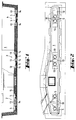
- a tundish (1) points for casting three Strands three recesses (2,3,4).
- the recesses (2,3,4) is a pair of runout blocks (5) used.
- Each outlet block (5) consists of a perforated brick (6) and a nozzle block (7) inserted in this.
- the perforated stone (6) has a rectangular, preferably square Outer contour on (see. Fig. 4).
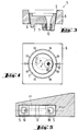
- the nozzle block (7) is with a rotationally symmetrical, especially circular, Provided peripheral surface (8) in a corresponding rotationally symmetrical recess (9) of the perforated brick (6) fits.
- the peripheral surface (8) and the recess (9) are designed conical (see. Fig. 3).
- the nozzle block (7) has an outlet opening (10) provided, which is eccentric to the axis of rotation (A) of the rotationally symmetrical peripheral surface (8).
- a mouthpiece (11) is arranged in the outlet opening (10).
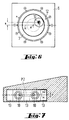
- At the Nozzle block (7) can also have a replacement outlet opening (10 ') can be provided when the former wear Outlet opening (10) can be put into operation.
- the replacement outlet opening (10 ') is expediently arranged diametrically to the outlet opening (10).
- the outlet opening is located (10) on the center line (M) of the outlet block (5).
- the 6 has the outlet opening (10) a distance (a) from the center line (M).
- the 8 is the outlet opening (10) in a distance (b) to the center line (M).
- the center line (M) of the discharge block (5) is in each case Longitudinal direction of the recesses (2,3,4).
- the recesses (2,3,4) are each longer than the total length of two Outlet blocks (5) in the direction of the center line (M).
- Which when installing the outlet blocks (5) in the recesses (2,3 or 4) resulting gaps are with fitting plates (13) filled out.
- the fitting plates (13) are on the distribution vessel (1) held by support elements (14) from below (see Fig. 1).
- the outlet blocks (5) fit into the Recesses (2, 3 or 4).
- appropriate guidance can help be provided or the rectangular perforated brick (6) deviate from the square basic shape.
- the profile (P1) be poured. Its ideal center line (m1) or the The center line of the associated mold coincides with the Center line (M) of the outlet block (5) together. That's why are two outlet blocks (5) with setting the 4 on the marking "0" used, the nozzle block of the right discharge block is set to the left mark "0" in FIG. 4.
- the profile (P2) should be poured. Its ideal center line (m2) deviates from the center line (M) of the discharge block (5) around the width (a) from. So that the outlet openings (10) on the ideal Center line (m2), two outlet blocks (5) used, in which the nozzle stones (7) in the 6, the nozzle block the left discharge block at the upper right marking "25” and the nozzle block of the right discharge block at the upper left marking "25” stands.
- a double T profile is intended (P3) can be poured.
- Its ideal center line (m3) lies around the width (b) next to the center line (M) of the Outlet blocks (5).
- FIGS. 5, 7, 9 are shown in FIG. 1 and 2 shown in the recesses (2,3 and 4).
- the Distribution vessel (1) can thus be three different ones Cast double T profiles. Should be on one or the other Place a different profile of the distribution vessel (1), for example a profile for which an outlet block (5) is enough to be poured, then will be in the appropriate Recess (2, 3 or 4) with only one outlet block (5) corresponding angular position of its nozzle block (7) used. The remaining space is with Fitting plates (13) closed.
- Distribution vessel (1) in the area of the outlet blocks (5) and Fitting plates (13) with a continuous lining layer (15).
Landscapes
- Engineering & Computer Science (AREA)
- Mechanical Engineering (AREA)
- Casting Support Devices, Ladles, And Melt Control Thereby (AREA)
- Continuous Casting (AREA)
- Paper (AREA)
Description
- Figur 1
- ein Verteilergefäß im Längsschnitt,
- Figur 2
- eine Draufsicht des Verteilergefässes,
- Figur 3
- einen Auslaufblock im Schnitt,
- Figur 4
- eine Draufsicht des Auslaufblocks mit einer ersten Einstellung seines Düsensteins,
- Figur 5
- ein Auslaufblockpaar in der Einstellung nach Fig.4 am Verteilergefäß,
- Figur 6
- den Auslaufblock in einer zweiten Einstellung seines Düsensteins,
- Figur 7
- ein Auslaufblockpaar in der Einstellung nach Fig. 6 am Verteilergefäß,
- Figur 8
- den Auslaufblock in einer dritten Einstellung seines Düsensteins und
- Figur 9
- ein Auslaufblockpaar in der Einstellung nach Fig. 8 am Verteilergefäß.
Claims (9)
- Verteilergefäß für eine Mehrstrang-Gießanlage zum Gießen gleicher oder unterschiedlicher Stahlprofile, an dem für jeden Strang mindestens ein Auslaufblock vorgesehen ist, der aus einem feuerfesten Lochstein und einem in diesen eingesetzten feuerfesten Düsenstein mit einer Auslauföffnung besteht,
dadurch gekennzeichnet,
daß der Düsenstein (7) eine rotationssymmetrische Umfangsfläche (8) aufweist, die in eine entsprechend rotationssymmetrische Ausnehmung (9) des Lochsteins (6) in verschiedenen Drehwinkellagen einsetzbar ist, und daß die Auslauföffnung (10) des Düsensteins (7) exzentrisch zur Rotationsachse (A) der rotationssymmetrischen Umfangsfläche (8) liegt. - Verteilergefäß nach Anspruch 1,
dadurch gekennzeichnet,
daß mindestens zwei Auslaufblöcke (5) in eine Ausnehmung (2,3,4) des Verteilergefässes (1) eingelegt sind und Zwischenräume zwischen dem Rand der Ausnehmung (2,3,4) und den Auslaufblöcken (5) mit feuerfestem Material ausgefüllt sind. - Verteilergefäß nach Anspruch 2,
dadurch gekennzeichnet,
daß als feuerfestes Material Paßplatten (13) in die Zwischenräume eingesetzt sind. - Verteilergefäß nach einem der vorhergehenden Ansprüche,
dadurch gekennzeichnet,
daß das Verteilergefäß (1) mehrere Ausnehmungen (2,3,4) aufweist, in die die Auslaufblöcke (5) eingesetzt sind. - Auslaufblock für ein metallurgisches Gefäß, insbesondere Verteilergefäß, der aus einem feuerfesten Lochstein (6) und einem in diesen eingesetzten feuerfesten Düsenstein (7) mit einer Auslauföffnung (10) besteht,
dadurch gekennzeichnet,
daß der Düsenstein (7) eine rotationssymmetrische Umfangsfläche (8) aufweist, die in eine entsprechend rotationssymmetrische Ausnehmung (9) des Lochsteins (6) in verschiedenen Drehwinkellagen einsetzbar ist, und daß die Auslauföffnung (10) des Düsensteins (7) exzentrisch zur Rotationsachse (A) der rotationssymmetrischen Umfangsfläche (8) liegt. - Auslaufblock nach Anspruch 5,
dadurch gekennzeichnet,
daß die Umfangsfläche (8) kreiskegelförmig ist. - Auslaufblock nach Anspruch 5 oder 6,
dadurch gekennzeichnet,
daß der Lochstein (6) rechteckig, insbesondere quadratisch, ist. - Auslaufblock nach einem der vorhergehenden Ansprüche,
dadurch gekennzeichnet,
daß im Düsenstein (7) eine Ersatz-Auslauföffnung vorgesehen ist. - Auslaufblock nach einem der vorhergehenden Ansprüche,
dadurch gekennzeichnet,
daß am Lochstein (6) Markierungen ausgebildet sind und am Düsenstein (7) eine Marke (12) vorgesehen ist.
Applications Claiming Priority (2)
| Application Number | Priority Date | Filing Date | Title |
|---|---|---|---|
| DE4338859A DE4338859A1 (de) | 1993-11-13 | 1993-11-13 | Verteilergefäß und Auslaufblock für dieses |
| DE4338859 | 1993-11-13 |
Publications (2)
| Publication Number | Publication Date |
|---|---|
| EP0653261A1 EP0653261A1 (de) | 1995-05-17 |
| EP0653261B1 true EP0653261B1 (de) | 1998-07-22 |
Family
ID=6502567
Family Applications (1)
| Application Number | Title | Priority Date | Filing Date |
|---|---|---|---|
| EP94116141A Expired - Lifetime EP0653261B1 (de) | 1993-11-13 | 1994-10-13 | Verteilergefäss und Auslaufblock für dieses |
Country Status (4)
| Country | Link |
|---|---|
| US (1) | US5494266A (de) |
| EP (1) | EP0653261B1 (de) |
| AT (1) | ATE168601T1 (de) |
| DE (2) | DE4338859A1 (de) |
Families Citing this family (7)
| Publication number | Priority date | Publication date | Assignee | Title |
|---|---|---|---|---|
| FR2720307B1 (fr) * | 1994-05-24 | 1996-08-23 | Boulonnais Terres Refractaires | Dispositif de guidage de l'acier en fusion dans un répartiteur. |
| US6083453A (en) * | 1997-12-12 | 2000-07-04 | Uss/Kobe Steel Company | Tundish having fume collection provisions |
| US7083420B2 (en) * | 2003-02-10 | 2006-08-01 | Leapfrog Enterprises, Inc. | Interactive handheld apparatus with stylus |
| MY153640A (en) | 2005-07-15 | 2015-03-13 | Vesuvius Crucible Co | Continuous casting tundish |
| DE102005061291B4 (de) * | 2005-12-20 | 2008-01-03 | Heraeus Electro-Nite International N.V. | Keramischer Lochstein und metallurgisches Gefäß |
| DE102007044126A1 (de) * | 2007-09-15 | 2009-04-02 | Refractory Intellectual Property Gmbh & Co. Kg | Feuerfester keramischer Lochstein |
| CN104209503B (zh) * | 2014-09-22 | 2016-05-25 | 山东钢铁股份有限公司 | 一种连铸中间包分装式偏心座砖及其应用 |
Family Cites Families (7)
| Publication number | Priority date | Publication date | Assignee | Title |
|---|---|---|---|---|
| AT210077B (de) * | 1957-02-11 | 1960-07-11 | Boehler & Co Ag Geb | Verfahren zum Stranggießen, insbesondere von schwer schmelzbaren Metallen |
| US3165795A (en) * | 1963-05-08 | 1965-01-19 | George C Bahm | Apparatus for teeming of molten metals |
| US3377006A (en) * | 1966-07-29 | 1968-04-09 | George C. Bahm | Apparatus for the teeming of molten metals |
| CH673239A5 (de) * | 1987-12-15 | 1990-02-28 | Stopinc Ag | |
| EP0352353B1 (de) * | 1988-07-28 | 1991-05-08 | INTRACON Handelsgesellschaft für Industriebedarf mbH | Pfannenlochstein für die Verschlussvorrichtung einer Giesspfanne |
| JPH03274210A (ja) * | 1990-03-26 | 1991-12-05 | Daido Steel Co Ltd | 溶融金属の出湯装置 |
| DE4024351A1 (de) * | 1990-07-27 | 1992-02-06 | Mannesmann Ag | Eingiesssystem zur einleitung einer schmelze |
-
1993
- 1993-11-13 DE DE4338859A patent/DE4338859A1/de not_active Withdrawn
-
1994
- 1994-10-13 AT AT94116141T patent/ATE168601T1/de not_active IP Right Cessation
- 1994-10-13 EP EP94116141A patent/EP0653261B1/de not_active Expired - Lifetime
- 1994-10-13 DE DE59406484T patent/DE59406484D1/de not_active Expired - Fee Related
- 1994-10-31 US US08/331,945 patent/US5494266A/en not_active Expired - Fee Related
Also Published As
| Publication number | Publication date |
|---|---|
| DE4338859A1 (de) | 1995-05-18 |
| US5494266A (en) | 1996-02-27 |
| ATE168601T1 (de) | 1998-08-15 |
| EP0653261A1 (de) | 1995-05-17 |
| DE59406484D1 (de) | 1998-08-27 |
Similar Documents
| Publication | Publication Date | Title |
|---|---|---|
| AT392431B (de) | Feuerfeste platte fuer einen gleitschieber-verschluss | |
| DE3823199A1 (de) | Schneidplatte fuer spanabhebende bearbeitung | |
| EP0727268B1 (de) | Schieberverschluss-system für einen Metallschmelze enthaltenden Behälter | |
| EP0653261B1 (de) | Verteilergefäss und Auslaufblock für dieses | |
| DE4320723A1 (de) | Eintauchausguß | |
| DE2933989C2 (de) | Vorrichtung zum Ablassen der Restschmelze und Schlacke aus einem Zwischenbehälter nach Gießende | |
| DE3432613C1 (de) | Feuerfeste Platte fuer Schieberverschluesse an metallurgischen Gefaessen | |
| AT395392B (de) | Verschlussplatte aus feuerfestem material fuer linear- oder drehschieberverschluesse | |
| DE3805071C2 (de) | ||
| DE3913750C1 (de) | ||
| DE69213160T2 (de) | Gebogene Kokille zum Bogenstranggiessen von dünnen Brammen | |
| DE3411769C2 (de) | Horizontalstranggießvorrichtung | |
| EP0083745B1 (de) | Verlängerte Ausgussdüse für Zwischenbehälter | |
| DE3232147A1 (de) | Schrumpfausgleichseinrichtung fuer den giessquerschnitt einer giessvorrichtung mit in giessrichtung bewegten kokillenwaenden | |
| DE3001107C2 (de) | Mobile Vorrichtung zur Aufnahme geschmolzenen Metalls | |
| DE3704326A1 (de) | Ausgusskoerper | |
| EP0529108B1 (de) | Schieberverschluss an metallurgischen Gefässen | |
| EP2543455B1 (de) | Feuerfeste keramische Schieberplatte und zugehöriges Schieberplattenset | |
| DE2459568A1 (de) | Verschlusschiebervorrichtung fuer feuerfeste behaelter | |
| EP0325646B1 (de) | Verschlusskörper für einen schiebeverschluss an einem metallschmelze enthaltenden gefäss sowie schiebeverschluss mit einem derartigen verschlusskörper | |
| DE2847614C2 (de) | Drehschieberverschlußanordnung für eine Gießpfanne | |
| EP0027105B1 (de) | Bogenstranggiessanlage | |
| EP0109348A1 (de) | Stopfenstangenanordnung an Abgussöfen und anderen metallurgischen Gefässen | |
| DE3706720A1 (de) | Stranggiessanlage mit zwei nebeneinander angeordneten druchlaufkokillen | |
| DD236915A5 (de) | Kipprinne zur fuehrung von schmelzfluessigem material |
Legal Events
| Date | Code | Title | Description |
|---|---|---|---|
| PUAI | Public reference made under article 153(3) epc to a published international application that has entered the european phase |
Free format text: ORIGINAL CODE: 0009012 |
|
| 17P | Request for examination filed |
Effective date: 19941013 |
|
| AK | Designated contracting states |
Kind code of ref document: A1 Designated state(s): AT BE CH DE DK ES FR GB GR IE IT LI LU NL PT SE |
|
| GRAG | Despatch of communication of intention to grant |
Free format text: ORIGINAL CODE: EPIDOS AGRA |
|
| 17Q | First examination report despatched |
Effective date: 19970909 |
|
| GRAG | Despatch of communication of intention to grant |
Free format text: ORIGINAL CODE: EPIDOS AGRA |
|
| GRAH | Despatch of communication of intention to grant a patent |
Free format text: ORIGINAL CODE: EPIDOS IGRA |
|
| GRAH | Despatch of communication of intention to grant a patent |
Free format text: ORIGINAL CODE: EPIDOS IGRA |
|
| GRAA | (expected) grant |
Free format text: ORIGINAL CODE: 0009210 |
|
| AK | Designated contracting states |
Kind code of ref document: B1 Designated state(s): AT BE CH DE DK ES FR GB GR IE IT LI LU NL PT SE |
|
| PG25 | Lapsed in a contracting state [announced via postgrant information from national office to epo] |
Ref country code: NL Free format text: LAPSE BECAUSE OF FAILURE TO SUBMIT A TRANSLATION OF THE DESCRIPTION OR TO PAY THE FEE WITHIN THE PRESCRIBED TIME-LIMIT Effective date: 19980722 Ref country code: IT Free format text: LAPSE BECAUSE OF FAILURE TO SUBMIT A TRANSLATION OF THE DESCRIPTION OR TO PAY THE FEE WITHIN THE PRESCRIBED TIME-LIMIT;WARNING: LAPSES OF ITALIAN PATENTS WITH EFFECTIVE DATE BEFORE 2007 MAY HAVE OCCURRED AT ANY TIME BEFORE 2007. THE CORRECT EFFECTIVE DATE MAY BE DIFFERENT FROM THE ONE RECORDED. Effective date: 19980722 Ref country code: GR Free format text: LAPSE BECAUSE OF FAILURE TO SUBMIT A TRANSLATION OF THE DESCRIPTION OR TO PAY THE FEE WITHIN THE PRESCRIBED TIME-LIMIT Effective date: 19980722 Ref country code: ES Free format text: THE PATENT HAS BEEN ANNULLED BY A DECISION OF A NATIONAL AUTHORITY Effective date: 19980722 |
|
| REF | Corresponds to: |
Ref document number: 168601 Country of ref document: AT Date of ref document: 19980815 Kind code of ref document: T |
|
| REG | Reference to a national code |
Ref country code: CH Ref legal event code: EP |
|
| ET | Fr: translation filed | ||
| GBT | Gb: translation of ep patent filed (gb section 77(6)(a)/1977) |
Effective date: 19980723 |
|
| REF | Corresponds to: |
Ref document number: 59406484 Country of ref document: DE Date of ref document: 19980827 |
|
| PGFP | Annual fee paid to national office [announced via postgrant information from national office to epo] |
Ref country code: GB Payment date: 19980914 Year of fee payment: 5 |
|
| PGFP | Annual fee paid to national office [announced via postgrant information from national office to epo] |
Ref country code: FR Payment date: 19980916 Year of fee payment: 5 |
|
| PGFP | Annual fee paid to national office [announced via postgrant information from national office to epo] |
Ref country code: DE Payment date: 19980922 Year of fee payment: 5 |
|
| PGFP | Annual fee paid to national office [announced via postgrant information from national office to epo] |
Ref country code: AT Payment date: 19980923 Year of fee payment: 5 |
|
| PGFP | Annual fee paid to national office [announced via postgrant information from national office to epo] |
Ref country code: BE Payment date: 19980925 Year of fee payment: 5 |
|
| PGFP | Annual fee paid to national office [announced via postgrant information from national office to epo] |
Ref country code: CH Payment date: 19980929 Year of fee payment: 5 |
|
| PG25 | Lapsed in a contracting state [announced via postgrant information from national office to epo] |
Ref country code: LU Free format text: LAPSE BECAUSE OF NON-PAYMENT OF DUE FEES Effective date: 19981013 |
|
| PG25 | Lapsed in a contracting state [announced via postgrant information from national office to epo] |
Ref country code: SE Free format text: LAPSE BECAUSE OF FAILURE TO SUBMIT A TRANSLATION OF THE DESCRIPTION OR TO PAY THE FEE WITHIN THE PRESCRIBED TIME-LIMIT Effective date: 19981022 Ref country code: PT Free format text: LAPSE BECAUSE OF FAILURE TO SUBMIT A TRANSLATION OF THE DESCRIPTION OR TO PAY THE FEE WITHIN THE PRESCRIBED TIME-LIMIT Effective date: 19981022 Ref country code: DK Free format text: LAPSE BECAUSE OF FAILURE TO SUBMIT A TRANSLATION OF THE DESCRIPTION OR TO PAY THE FEE WITHIN THE PRESCRIBED TIME-LIMIT Effective date: 19981022 |
|
| REG | Reference to a national code |
Ref country code: IE Ref legal event code: FG4D Free format text: GERMAN |
|
| NLV1 | Nl: lapsed or annulled due to failure to fulfill the requirements of art. 29p and 29m of the patents act | ||
| PG25 | Lapsed in a contracting state [announced via postgrant information from national office to epo] |
Ref country code: IE Free format text: LAPSE BECAUSE OF NON-PAYMENT OF DUE FEES Effective date: 19990219 |
|
| REG | Reference to a national code |
Ref country code: IE Ref legal event code: FD4D |
|
| PLBE | No opposition filed within time limit |
Free format text: ORIGINAL CODE: 0009261 |
|
| STAA | Information on the status of an ep patent application or granted ep patent |
Free format text: STATUS: NO OPPOSITION FILED WITHIN TIME LIMIT |
|
| 26N | No opposition filed | ||
| PG25 | Lapsed in a contracting state [announced via postgrant information from national office to epo] |
Ref country code: GB Free format text: LAPSE BECAUSE OF NON-PAYMENT OF DUE FEES Effective date: 19991013 Ref country code: AT Free format text: LAPSE BECAUSE OF NON-PAYMENT OF DUE FEES Effective date: 19991013 |
|
| PG25 | Lapsed in a contracting state [announced via postgrant information from national office to epo] |
Ref country code: LI Free format text: LAPSE BECAUSE OF NON-PAYMENT OF DUE FEES Effective date: 19991031 Ref country code: CH Free format text: LAPSE BECAUSE OF NON-PAYMENT OF DUE FEES Effective date: 19991031 Ref country code: BE Free format text: LAPSE BECAUSE OF NON-PAYMENT OF DUE FEES Effective date: 19991031 |
|
| BERE | Be: lapsed |
Owner name: DIDIER-WERKE A.G. Effective date: 19991031 |
|
| GBPC | Gb: european patent ceased through non-payment of renewal fee |
Effective date: 19991013 |
|
| REG | Reference to a national code |
Ref country code: CH Ref legal event code: PL |
|
| PG25 | Lapsed in a contracting state [announced via postgrant information from national office to epo] |
Ref country code: FR Free format text: LAPSE BECAUSE OF NON-PAYMENT OF DUE FEES Effective date: 20000630 |
|
| PG25 | Lapsed in a contracting state [announced via postgrant information from national office to epo] |
Ref country code: DE Free format text: LAPSE BECAUSE OF NON-PAYMENT OF DUE FEES Effective date: 20000801 |
|
| REG | Reference to a national code |
Ref country code: FR Ref legal event code: ST |