EP0652467A1 - Kamera zur Verwendung mit einer Filmkassette mit lichtundurchlässigem beweglichem Abschlusselement - Google Patents
Kamera zur Verwendung mit einer Filmkassette mit lichtundurchlässigem beweglichem Abschlusselement Download PDFInfo
- Publication number
- EP0652467A1 EP0652467A1 EP94307950A EP94307950A EP0652467A1 EP 0652467 A1 EP0652467 A1 EP 0652467A1 EP 94307950 A EP94307950 A EP 94307950A EP 94307950 A EP94307950 A EP 94307950A EP 0652467 A1 EP0652467 A1 EP 0652467A1
- Authority
- EP
- European Patent Office
- Prior art keywords
- cartridge
- cover
- camera
- inhibition
- light shield
- Prior art date
- Legal status (The legal status is an assumption and is not a legal conclusion. Google has not performed a legal analysis and makes no representation as to the accuracy of the status listed.)
- Granted
Links
- 230000005764 inhibitory process Effects 0.000 claims abstract description 17
- 230000002401 inhibitory effect Effects 0.000 claims abstract description 7
- 230000005540 biological transmission Effects 0.000 description 5
- 238000001514 detection method Methods 0.000 description 4
- 230000000994 depressogenic effect Effects 0.000 description 3
- 238000012986 modification Methods 0.000 description 2
- 230000004048 modification Effects 0.000 description 2
- 230000003287 optical effect Effects 0.000 description 2
- VRDIULHPQTYCLN-UHFFFAOYSA-N Prothionamide Chemical compound CCCC1=CC(C(N)=S)=CC=N1 VRDIULHPQTYCLN-UHFFFAOYSA-N 0.000 description 1
- 238000010276 construction Methods 0.000 description 1
- 230000000881 depressing effect Effects 0.000 description 1
- 230000011514 reflex Effects 0.000 description 1
Images


Classifications
-
- G—PHYSICS
- G03—PHOTOGRAPHY; CINEMATOGRAPHY; ANALOGOUS TECHNIQUES USING WAVES OTHER THAN OPTICAL WAVES; ELECTROGRAPHY; HOLOGRAPHY
- G03B—APPARATUS OR ARRANGEMENTS FOR TAKING PHOTOGRAPHS OR FOR PROJECTING OR VIEWING THEM; APPARATUS OR ARRANGEMENTS EMPLOYING ANALOGOUS TECHNIQUES USING WAVES OTHER THAN OPTICAL WAVES; ACCESSORIES THEREFOR
- G03B17/00—Details of cameras or camera bodies; Accessories therefor
- G03B17/28—Locating light-sensitive material within camera
- G03B17/30—Locating spools or other rotatable holders of coiled film
-
- G—PHYSICS
- G03—PHOTOGRAPHY; CINEMATOGRAPHY; ANALOGOUS TECHNIQUES USING WAVES OTHER THAN OPTICAL WAVES; ELECTROGRAPHY; HOLOGRAPHY
- G03B—APPARATUS OR ARRANGEMENTS FOR TAKING PHOTOGRAPHS OR FOR PROJECTING OR VIEWING THEM; APPARATUS OR ARRANGEMENTS EMPLOYING ANALOGOUS TECHNIQUES USING WAVES OTHER THAN OPTICAL WAVES; ACCESSORIES THEREFOR
- G03B2217/00—Details of cameras or camera bodies; Accessories therefor
- G03B2217/26—Holders for containing light-sensitive material and adapted to be inserted within the camera
- G03B2217/268—Unloading the cartridge from the camera; Loading the cartridge into the camera
Definitions
- the present invention relates to an improvement in a camera adapted to use a film cartridge having a movable light shield door.
- Cameras each having a movable light shield door opening/closing device for opening/closing a movable light shield door formed on a film cartridge are disclosed in Japanese Laid-Open Patent Application Nos. 1-191836 and 1-191837.
- a switch for detecting if a cartridge chamber cover is closed detects that the cartridge chamber cover is closed, a movable light shield door is opened, and a film is extracted via the movable light shield door to prevent film exposure. After a predetermined period of time has elapsed from the end of the rewind operation of a film, if the movable light shield door is kept open, an alarm is generated.
- the prior art describes an embodiment which prevents inadvertent exposure of a film by inhibiting the cartridge chamber cover from being opened when the movable light shield door is open.
- the movable light shield door is also disclosed in U.S. Patent No. 4,938,429.
- a light shield door is opened/closed by pivoting a rotatable shaft.
- an operation member for opening/closing the cartridge chamber cover of a camera is locked while the movable light shield door is open.
- a lock member for locking the operation member is operated integrally with the movable light shield door by the driving force from a motor.
- the lock member cannot be operated even if the lock member can be forcibly externally operated.
- One aspect of the present invention is to provide a camera or apparatus adapted to use an image recording medium cartridge having a cover for allowing an image recording medium to exit from or withdraw into the image recording medium cartridge, or a device adapted in the camera or apparatus, which camera or apparatus comprises inhibition means for, when the cover of the cartridge loaded in the camera or apparatus is open, inhibiting the cartridge from being unloaded from the camera or apparatus, and disabling means for disabling an operation of the inhibition means when the cover of the cartridge loaded in the camera or apparatus is open, which camera or apparatus allows the cartridge to be unloaded from the camera or apparatus even when the cover of the cartridge loaded in the camera or apparatus is kept open and cannot be closed due to some accident.
- Figs. 1 to 4B show the first embodiment of the present invention
- Fig. 1 is a perspective view showing the outer appearance of a camera according to the first embodiment of the present invention.
- the camera includes a camera main body 1, a phototaking lens 2, a shutter button 3, a finder 4, a cartridge chamber cover 5 which opens/closes a cartridge chamber arranged in the camera main body 1 and allows loading/unloading of a film cartridge (to be described later), and a hinge shaft 6 which rotatably couples the cartridge chamber cover 5 to the camera main body, and allows opening/closing of the cartridge chamber.
- the camera also includes an operation member 7 for opening/closing the cartridge chamber cover 5, and a release button 8 for releasing a locked state of the operation member 7 in an emergency state.
- the camera includes a notch 5a for allowing the operation member 7 to be slidable, and a hole 5b for operating the release button 8.
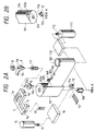
- Figs. 2A and 2B are perspective views showing the mechanical arrangements of principal portions of the camera.
- the camera includes a film cartridge 101 which is loaded in the cartridge chamber in the camera main body 1 and stores a film, a shaft 102 used for feeding a film in the film cartridge 101, and an engaging portion 103 for opening/closing a movable light shield door of the film cartridge 101.
- the engaging portion 103 integrally has engaging grooves 103a and 103b at the two end portions of the film cartridge 101.
- the camera also includes a movable light shield door 104 for opening/closing a film exit/entrance opening of the film cartridge 101, a film 105 with perforations 106, a spool 107 for taking up the film 105, and a photoreflector 108 for detecting the perforations 106 of the film 105.
- the camera further includes a power transmission fork 109 which is engaged with the film feed shaft 102 in the loaded film cartridge 101 to feed (push out) the film 105 from the film cartridge 101 or to rewind the film.
- the camera includes a power transmission mechanism 110 for transmitting power to the fork 109 and the take-up spool 107, a film feed motor 111, and an output gear 112, of the film feed motor 111, for transmitting the output from the film feed motor 111 to the power transmission mechanism 110.
- the operation member 7, which is partially shown in Fig. 1, is constituted by the following members 7a to 7d (the cartridge chamber cover 5 is not shown in Figs. 2A and 2B).
- the operation member 7 is constituted by an operation portion 7a, a pawl portion 7b which is engaged with an engaging portion (not shown) provided to the camera main body 1 to hold the cartridge chamber cover 5 in a closed state, a lock portion 7c for locking the operation member 7 in an inoperable state, and an electrical contact 7d on the operation member 7.
- the electrical contact 7d is electrically connected to a cartridge chamber cover opening/closing detection switch 17, i.e., the cartridge chamber cover opening/closing detection switch 17 is turned on.
- a lock member 9 is used for setting the operation member 7 in an inoperable state, and has a flat round hole 9a and a lock pawl 9b to be engaged with the lock portion 7c of the operation member 7.
- a driven member 10 is engaged with the engaging portion 103 provided to the film cartridge 101, and has a flat round engaging portion 10a which is engaged with the flat round hole 9a of the lock member 9, and an engaging pawl 10b which is engaged with the engaging groove 103a of the engaging portion 103.
- a spring 11 is arranged between the lock member 9 and the driven member 10 to push up the lock member 9 from the lower side and to push down the driven member 10 from the upper side.
- the release button 8 When the release button 8 is depressed, the lock member 9 can be swung in the vertical direction upon operation of the spring 11.
- the engaging pawl 10b of the driven member 10 cannot be satisfactorily engaged with the engaging groove 103a of the engaging portion 103, the discrepancy can be absorbed by the spring 11, and later, the engaging pawl 10b can be satisfactorily engaged with the engaging groove 103a upon pivotal movement of the movable light shield door 104.
- a driving member 12 is engaged with the engaging portion 103, and has an engaging pawl 12a to be engaged with the engaging groove 103b and an electrical contact 12b arranged on a circumference having the rotational shaft of the driving member 12 as the center.
- a movable light shield door opening/closing detection switch 13 is electrically connected to the electrical contact 12b of the driving member 12, i.e., is turned on when the movable light shield door 104 is open while the film 105 is extracted from the film cartridge 101, as shown in Fig. 2A (in Fig. 2B, the movable light shield door 104 is closed).
- a power transmission mechanism 14 is used for driving the driving member 12.
- a motor 15 opens/closes the movable light shield door via an output gear 16 for transmitting an output from the movable light shield door opening/closing motor 15 to the power transmission mechanism 14.
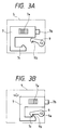
- Figs. 3A and 3B are plan views showing a state wherein the operation member 7 is operated.
- Fig. 3A shows a state wherein the cartridge chamber cover 5 can be opened.
- the operation member 7 is located at a position where the cartridge chamber cover 5 can be opened about the hinge shaft 6 shown in Fig. 1, and the lock member 9 is located at a position where the movable light shield door 104 is closed.
- Fig. 3B shows a state wherein the cartridge chamber cover 5 is closed.
- the operation portion 7a of the operation member 7 is slid in the direction of an arrow in Fig. 3B, the pawl portion 7b is engaged with the engaging portion (not shown) provided to the camera main body 1, and the cartridge chamber cover 5 is held in a closed state.
- the cartridge chamber cover opening/closing detection switch 17 shown in Figs. 2A and 2B is turned on, and the movable light shield door opening/closing motor 15 is started by a motor control circuit (not shown), thereby opening the movable light shield door 104 via the driving member 12.
- the engaging pawl 10b of the driven member 10 which is engaged with the engaging groove 103a of the engaging portion 103 is pivoted counterclockwise to follow the movement of the movable light shield door 104.
- the pivot force is transmitted to the flat round hole 9a coaxially engaged with the flat round engaging protion 10a, and the lock member 9 is pivoted counterclockwise.
- the lock pawl 9b is engaged with the lock portion 7c, and locks the operation member 7 at a position for inhibiting the cartridge chamber cover 5 from being opened, so that the film 105 in the loaded film cartridge 101 can be prevented from being inadvertently exposed by opening the cartridge chamber cover 5 (see Fig. 3B).
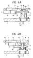
- Figs. 4A and 4B are sectional views showing a state wherein the operation member 7 is operated.
- Fig. 4A corresponds to the state shown in Fig. 3A, and shows a state wherein the cartridge chamber cover 5 is openable. In this state, the release button 8 is not depressed, and the lock member 9 is pushed upward by the spring 11. Note that the release button 8 is preferably arranged at a level equal to or lower than that of the surface of the cartridge chamber cover 5 so as not to be easily operated in a state other than an emergency state for the purpose of preventing inadvertent exposure.
- the cartridge chamber cover 5 can be opened to extract the film cartridge 101 by sliding the operation member 7 in a direction to open the cartridge chamber cover 5.
- the release button 8 and the lock member 9 are separately arranged but may be integrally arranged. If the lock member 9 or the driven member 10 is provided with a weak spring for biasing in the clockwise direction, the engaging pawl 10b can be reliably engaged with the engaging groove 103a of the engaging portion 103 when the movable light shield door 104 is closed.
- Fig. 5 is a perspective view showing the mechanical arrangement of principal portions of a camera according to the second embodiment of the present invention, and the same reference numerals in Fig. 5 denote the same parts as in Figs. 2A and 2B.
- the locked state is released by depressing the lock release mechanism (the release button 8 and the lock member 9) in the thickness direction.
- the locked state is released by rotating the lock release mechanism clockwise.
- a driven member 50 of the engaging portion 103 has an engaging hole 50a to be pivotally engaged with a lock member (to be described later), an engaging pawl portion 50b to be engaged with the engaging groove 103a of the engaging portion 103, and a friction surface 50c to which a friction spring (to be described later) is attached.
- a lock member 60 is used for locking the operation member 7 in an inoperable state.
- the lock member 60 has an engaging shaft 60a to be pivotally engaged with the engaging hole 50a of the driven member 50, a locking hole 60b for locking one end of a friction spring (to be described later), a lock pawl 60c to be engaged with the lock portion 7c of the operation member 7, and a groove 60d capable of receiving a plus screwdriver to allow, e.g., the plus screwdriver to pivot the lock member 60 in only an emergency state.
- a clockwise friction spring 70 has an engaging portion 70a at which the friction spring 70 is locked.
- the driven member 50 When the movable light shield door 104 is closed, the driven member 50 is pivoted clockwise. At this time, the friction spring has a fastening direction with respect to the driven member 50, and the lock member 60 is integrally pivoted clockwise, thus setting the operation member 7 in an operable state.
- the movable light shield door 104 cannot be closed from an open state due to some accident, if, e.g., a plus screwdriver is inserted in the groove 60d of the lock member 60 and is pivoted clockwise, since the movable light shield door 104 is not closed due to the interference of the film 105 present at the film port, the driven member 50 and the friction spring 70 slip, and only the lock member 60 is pivoted clockwise, thus allowing the operation member 7 to be operable. As a result, the cartridge chamber cover 5 can be opened. In this case, since the friction spring 70 is pivoted in the direction to loosen, the movable light shield door 104 will not strongly push the film 105 even if it bites the film 105, thus preventing the film 105 from being damaged.
- the groove 60d is a groove capable of receiving a plus screwdriver.
- the groove 60d may be any other grooves such as a minus groove, L-groove, and the like as long as the lock member 60 can be externally pivoted.
- a projection may be formed in place of a groove. That is, the groove 60d need only have a shape which does not allow an easy operation to prevent inadvertent exposure in a state other than an emergency state.
- a driving system for driving the engaging groove 103b is arranged at an engaging groove 103b side of the engaging grooves 103a and 103b at the two end portions of the film cartridge 101, and the lock members 9 and 60 driven by the engaging groove 103a are arranged at the engaging groove 103a side.
- a mechanism having a relationship between the driving and driven sides properly utilizing the engaging grooves 103a and 103b at the two end portions of the film cartridge 101 can be arranged with a high space efficiency and a high degree of design freedom.
- an arrangement other than the lock members 9 and 60 may be arranged at the driven side to perform a predetermined operation.
- the operation member 7 for opening/closing the cartridge chamber cover 5 can be operated by the lock release means (the release button 8 or the groove 60d capable of receiving a plus screwdriver) of the lock member 9 or 60. For this reason, if this operation is performed in, e.g., a dark room, the film cartridge 101 can be unloaded from the camera main body 1 without exposing the film 105.
- the present invention can be applied to a device which uses a cartridge having a movable light shield door or the like, which has a shape other than that described in the above specification.
- the present invention can be applied to image recording media other than a film.
- the present invention can be applied to a device which uses a cartridge of a type other than that described in the above specification, a cartridge having an image recording medium other than a film, various other cartridges, and a member to be loaded other than a cartridge.
- all or some constituting elements of the claims or embodiments may constitute a single device, a device to be combined with another device, or an element constituting a device.
- the present invention can be applied to various types of cameras such as a single-lens reflex camera, a lens shutter camera, a video camera, and the like, optical equipment or apparatuses other than a camera, a device adopted in these cameras, optical equipment, or apparatuses, or an element constituting these.
- cameras such as a single-lens reflex camera, a lens shutter camera, a video camera, and the like, optical equipment or apparatuses other than a camera, a device adopted in these cameras, optical equipment, or apparatuses, or an element constituting these.
Landscapes
- Physics & Mathematics (AREA)
- General Physics & Mathematics (AREA)
- Details Of Cameras Including Film Mechanisms (AREA)
- Camera Bodies And Camera Details Or Accessories (AREA)
Applications Claiming Priority (3)
| Application Number | Priority Date | Filing Date | Title |
|---|---|---|---|
| JP292482/93 | 1993-10-29 | ||
| JP29248293 | 1993-10-29 | ||
| JP5292482A JPH07128716A (ja) | 1993-10-29 | 1993-10-29 | カメラ |
Publications (2)
| Publication Number | Publication Date |
|---|---|
| EP0652467A1 true EP0652467A1 (de) | 1995-05-10 |
| EP0652467B1 EP0652467B1 (de) | 2000-05-24 |
Family
ID=17782389
Family Applications (1)
| Application Number | Title | Priority Date | Filing Date |
|---|---|---|---|
| EP94307950A Expired - Lifetime EP0652467B1 (de) | 1993-10-29 | 1994-10-28 | Kamera zur Verwendung mit einer Filmkassette mit lichtundurchlässigem beweglichem Abschlusselement |
Country Status (6)
| Country | Link |
|---|---|
| US (1) | US6220770B1 (de) |
| EP (1) | EP0652467B1 (de) |
| JP (1) | JPH07128716A (de) |
| CN (1) | CN1065968C (de) |
| DE (1) | DE69424624T2 (de) |
| TW (1) | TW299402B (de) |
Cited By (1)
| Publication number | Priority date | Publication date | Assignee | Title |
|---|---|---|---|---|
| US5619298A (en) * | 1996-02-13 | 1997-04-08 | Eastman Kodak Company | Film rewinding apparatus for use in case of camera malfunction |
Families Citing this family (2)
| Publication number | Priority date | Publication date | Assignee | Title |
|---|---|---|---|---|
| US5715495A (en) * | 1995-06-15 | 1998-02-03 | Nikon Corporation | Apparatus having a locking mechanism for cartridge chamber lid |
| USD552141S1 (en) * | 2005-11-14 | 2007-10-02 | Pure Digital Technologies, Inc. | Digital video recorder device |
Citations (3)
| Publication number | Priority date | Publication date | Assignee | Title |
|---|---|---|---|---|
| JPH01191836A (ja) * | 1988-01-27 | 1989-08-01 | Canon Inc | カメラおよびカートリッジ装填装置 |
| US4938429A (en) * | 1989-01-12 | 1990-07-03 | Eastman Kodak Co. | Film cassette |
| JPH05150344A (ja) * | 1991-11-21 | 1993-06-18 | Nikon Corp | フイルムカートリツジ取り出し装置 |
Family Cites Families (8)
| Publication number | Priority date | Publication date | Assignee | Title |
|---|---|---|---|---|
| US4339193A (en) * | 1981-05-06 | 1982-07-13 | Eastman Kodak Company | Camera door and body construction |
| JP2648160B2 (ja) | 1988-01-27 | 1997-08-27 | キヤノン株式会社 | カメラおよびフィルム送り装置 |
| US5231438A (en) | 1991-11-25 | 1993-07-27 | Eastman Kodak Company | Camera with interlock for cover piece and cartridge light shield |
| JPH06186675A (ja) * | 1992-12-16 | 1994-07-08 | Fuji Photo Film Co Ltd | レンズ付きフイルムユニット |
| US5754904A (en) * | 1993-02-03 | 1998-05-19 | Canon Kabushiki Kaisha | Camera utilizing cartridge with movable light shield cover |
| JPH06258699A (ja) * | 1993-03-05 | 1994-09-16 | Minolta Camera Co Ltd | カメラのカートリッジ室蓋ロック機構 |
| US5473401A (en) * | 1993-03-19 | 1995-12-05 | Olympus Optical Co., Ltd. | Camera having a locking mechanism for preventing accidental opening of a back cover |
| JP3169196B2 (ja) * | 1993-08-10 | 2001-05-21 | オリンパス光学工業株式会社 | カメラ |
-
1993
- 1993-10-29 JP JP5292482A patent/JPH07128716A/ja active Pending
-
1994
- 1994-10-26 US US08/328,864 patent/US6220770B1/en not_active Expired - Fee Related
- 1994-10-28 DE DE69424624T patent/DE69424624T2/de not_active Expired - Fee Related
- 1994-10-28 EP EP94307950A patent/EP0652467B1/de not_active Expired - Lifetime
- 1994-10-28 CN CN94119347.0A patent/CN1065968C/zh not_active Expired - Fee Related
- 1994-11-02 TW TW083110106A patent/TW299402B/zh active
Patent Citations (3)
| Publication number | Priority date | Publication date | Assignee | Title |
|---|---|---|---|---|
| JPH01191836A (ja) * | 1988-01-27 | 1989-08-01 | Canon Inc | カメラおよびカートリッジ装填装置 |
| US4938429A (en) * | 1989-01-12 | 1990-07-03 | Eastman Kodak Co. | Film cassette |
| JPH05150344A (ja) * | 1991-11-21 | 1993-06-18 | Nikon Corp | フイルムカートリツジ取り出し装置 |
Non-Patent Citations (2)
| Title |
|---|
| PATENT ABSTRACTS OF JAPAN vol. 13, no. 482 (P - 953) 2 November 1989 (1989-11-02) * |
| PATENT ABSTRACTS OF JAPAN vol. 17, no. 539 (P - 1621) 28 September 1993 (1993-09-28) * |
Cited By (1)
| Publication number | Priority date | Publication date | Assignee | Title |
|---|---|---|---|---|
| US5619298A (en) * | 1996-02-13 | 1997-04-08 | Eastman Kodak Company | Film rewinding apparatus for use in case of camera malfunction |
Also Published As
| Publication number | Publication date |
|---|---|
| CN1065968C (zh) | 2001-05-16 |
| DE69424624T2 (de) | 2001-01-25 |
| US6220770B1 (en) | 2001-04-24 |
| CN1115868A (zh) | 1996-01-31 |
| TW299402B (de) | 1997-03-01 |
| EP0652467B1 (de) | 2000-05-24 |
| DE69424624D1 (de) | 2000-06-29 |
| JPH07128716A (ja) | 1995-05-19 |
Similar Documents
| Publication | Publication Date | Title |
|---|---|---|
| US5565951A (en) | Camera | |
| US5600393A (en) | Mechanism for opening and closing cartridge compartment cover of camera | |
| JPH0887064A (ja) | カメラのカートリッジ室ドアのロック装置 | |
| EP0652467B1 (de) | Kamera zur Verwendung mit einer Filmkassette mit lichtundurchlässigem beweglichem Abschlusselement | |
| US5555057A (en) | Differential gear for motor driven photographic system | |
| US5903791A (en) | Mechanism for locking and unlocking cover of cartridge compartment | |
| KR100186896B1 (ko) | 가동차광도어를 지닌 필름카트리지를 사용하도록 적용되는 카메라 또는 장치, 또는 그들에 적용되는 유닛 | |
| US6618562B2 (en) | Camera | |
| JP3152565B2 (ja) | カメラ | |
| JP2811644B2 (ja) | カメラ及びカートリッジ装填装置 | |
| JP3376083B2 (ja) | カメラ | |
| EP0679928B1 (de) | Gerät zum Laden einer Patrone mit beweglichem Lichtschutzdeckel | |
| US5740486A (en) | Camera having emergency cartridge taking-out function | |
| US5933669A (en) | Film winding mechanism with reduced space requirements | |
| JP3230326B2 (ja) | カメラ | |
| US20010028795A1 (en) | Camera | |
| JP2941185B2 (ja) | カメラ | |
| US6442353B2 (en) | Camera | |
| JPH08179411A (ja) | カメラ | |
| JP2000347268A (ja) | カメラ | |
| JP2001109048A (ja) | カメラのカートリッジ室蓋ロック装置 | |
| JP2003228119A (ja) | カートリッジ装填式機器 | |
| JP2003233112A (ja) | カメラの動力切り替え装置 | |
| JP2000081660A (ja) | カメラのフイルムカートリッジ装填装置 | |
| JP2000147625A (ja) | カメラ |
Legal Events
| Date | Code | Title | Description |
|---|---|---|---|
| PUAI | Public reference made under article 153(3) epc to a published international application that has entered the european phase |
Free format text: ORIGINAL CODE: 0009012 |
|
| AK | Designated contracting states |
Kind code of ref document: A1 Designated state(s): DE FR GB |
|
| 17P | Request for examination filed |
Effective date: 19950925 |
|
| 17Q | First examination report despatched |
Effective date: 19970623 |
|
| GRAG | Despatch of communication of intention to grant |
Free format text: ORIGINAL CODE: EPIDOS AGRA |
|
| GRAG | Despatch of communication of intention to grant |
Free format text: ORIGINAL CODE: EPIDOS AGRA |
|
| GRAH | Despatch of communication of intention to grant a patent |
Free format text: ORIGINAL CODE: EPIDOS IGRA |
|
| GRAH | Despatch of communication of intention to grant a patent |
Free format text: ORIGINAL CODE: EPIDOS IGRA |
|
| GRAA | (expected) grant |
Free format text: ORIGINAL CODE: 0009210 |
|
| AK | Designated contracting states |
Kind code of ref document: B1 Designated state(s): DE FR GB |
|
| PG25 | Lapsed in a contracting state [announced via postgrant information from national office to epo] |
Ref country code: FR Free format text: LAPSE BECAUSE OF FAILURE TO SUBMIT A TRANSLATION OF THE DESCRIPTION OR TO PAY THE FEE WITHIN THE PRESCRIBED TIME-LIMIT Effective date: 20000524 |
|
| REF | Corresponds to: |
Ref document number: 69424624 Country of ref document: DE Date of ref document: 20000629 |
|
| EN | Fr: translation not filed | ||
| PG25 | Lapsed in a contracting state [announced via postgrant information from national office to epo] |
Ref country code: GB Free format text: LAPSE BECAUSE OF NON-PAYMENT OF DUE FEES Effective date: 20001028 |
|
| PLBE | No opposition filed within time limit |
Free format text: ORIGINAL CODE: 0009261 |
|
| STAA | Information on the status of an ep patent application or granted ep patent |
Free format text: STATUS: NO OPPOSITION FILED WITHIN TIME LIMIT |
|
| 26N | No opposition filed | ||
| GBPC | Gb: european patent ceased through non-payment of renewal fee |
Effective date: 20001028 |
|
| PGFP | Annual fee paid to national office [announced via postgrant information from national office to epo] |
Ref country code: DE Payment date: 20071031 Year of fee payment: 14 |
|
| PG25 | Lapsed in a contracting state [announced via postgrant information from national office to epo] |
Ref country code: DE Free format text: LAPSE BECAUSE OF NON-PAYMENT OF DUE FEES Effective date: 20090501 |