EP0650834B1 - Vorrichtung und Verfahren zum Reinigen der Farbvorrichtung einer Druckmaschine oder Lackierer - Google Patents
Vorrichtung und Verfahren zum Reinigen der Farbvorrichtung einer Druckmaschine oder Lackierer Download PDFInfo
- Publication number
- EP0650834B1 EP0650834B1 EP94116024A EP94116024A EP0650834B1 EP 0650834 B1 EP0650834 B1 EP 0650834B1 EP 94116024 A EP94116024 A EP 94116024A EP 94116024 A EP94116024 A EP 94116024A EP 0650834 B1 EP0650834 B1 EP 0650834B1
- Authority
- EP
- European Patent Office
- Prior art keywords
- solvent
- ink
- pump
- source
- chamber
- Prior art date
- Legal status (The legal status is an assumption and is not a legal conclusion. Google has not performed a legal analysis and makes no representation as to the accuracy of the status listed.)
- Expired - Lifetime
Links
- 238000005406 washing Methods 0.000 title claims description 10
- 238000000034 method Methods 0.000 title claims description 8
- 239000002904 solvent Substances 0.000 claims description 151
- 239000002699 waste material Substances 0.000 claims description 27
- 230000002441 reversible effect Effects 0.000 claims description 13
- 238000007774 anilox coating Methods 0.000 claims description 11
- 239000012530 fluid Substances 0.000 claims description 10
- 239000010887 waste solvent Substances 0.000 claims description 6
- 238000005086 pumping Methods 0.000 claims description 4
- 230000008878 coupling Effects 0.000 claims 1
- 238000010168 coupling process Methods 0.000 claims 1
- 238000005859 coupling reaction Methods 0.000 claims 1
- 239000000976 ink Substances 0.000 description 56
- 239000007787 solid Substances 0.000 description 4
- 238000004140 cleaning Methods 0.000 description 3
- 238000011010 flushing procedure Methods 0.000 description 3
- 230000008901 benefit Effects 0.000 description 2
- 230000008602 contraction Effects 0.000 description 2
- 230000005484 gravity Effects 0.000 description 2
- 239000007788 liquid Substances 0.000 description 2
- 239000000203 mixture Substances 0.000 description 2
- XLYOFNOQVPJJNP-UHFFFAOYSA-N water Substances O XLYOFNOQVPJJNP-UHFFFAOYSA-N 0.000 description 2
- 230000009471 action Effects 0.000 description 1
- 230000008859 change Effects 0.000 description 1
- 230000003749 cleanliness Effects 0.000 description 1
- 230000001351 cycling effect Effects 0.000 description 1
- 239000000463 material Substances 0.000 description 1
- 230000009467 reduction Effects 0.000 description 1
- 230000003252 repetitive effect Effects 0.000 description 1
- 238000009991 scouring Methods 0.000 description 1
Images


Classifications
-
- B—PERFORMING OPERATIONS; TRANSPORTING
- B41—PRINTING; LINING MACHINES; TYPEWRITERS; STAMPS
- B41F—PRINTING MACHINES OR PRESSES
- B41F35/00—Cleaning arrangements or devices
- B41F35/04—Cleaning arrangements or devices for inking rollers
-
- B—PERFORMING OPERATIONS; TRANSPORTING
- B41—PRINTING; LINING MACHINES; TYPEWRITERS; STAMPS
- B41F—PRINTING MACHINES OR PRESSES
- B41F35/00—Cleaning arrangements or devices
Definitions
- This invention relates to a method and apparatus for washing the deck of a press or coater and, more particularly to one having an enclosed doctor blade chamber for metering the solution onto a roll such as a flexographic anilox roll or a gravure roll.
- a roll such as a flexographic anilox roll or a gravure roll.
- a further complication lies in the fact that to get the job done efficiently, high flow rates are employed, particularly for creating turbulent flow so as to thoroughly cleanse the chamber.
- the end seals normally employed are capable of withstanding only slight pressure, i.e., of the order of 254 to 381 Pa (10 to 15" H 2 O). A higher flow rate can cause leakage past the end seals. Therefore, the wash-up job has taken longer than desired.
- fresh or once used solvent is drawn into the valve-equipped system while the remaining ink or waste solvent is being pumped into the waste receiver.
- valves shift allowing the pump to circulate the solvent through a closed circuit or loop which allows the highly desirable higher flow rates.
- the pump rotation can be repetitively cycled between forward and reverse directions to enhance the cleaning action of the solvent.
- the solvent may be any fluid used to dilute the ink components and carry away the ink solids -- for example, water for a water-based ink.
- the system then may be recharged with fresh solvent where once used solvent has been employed. Thereafter the system is drained of solvent which is replaced by air. In this way nearly all components of the inking system (hoses, pump, anilox roll, doctor blade chamber, valves, fittings, etc.) are automatically cleaned and made ready for the next printing job.
- a solvent saver i.e., an addition to the system to first circulate once used solvent for a preliminary cleaning of the system. This results in a material reduction of solvent required -- from about 7.6 litres (two gallons) per deck to about 3.8 litres (one gallon).
- a fifth valve is employed along with an additional receiver over the basic system.
- This receiver advantageous has a volume approximately equal to the volume of the system, i.e., volume in the hoses, pump, chamber and valves.
- Three passages lead from the additional receiver, two return lines and one suction line. The discharge ends of the return lines are positioned above the expected solvent level in the additional receiver whereas the suction line end draws from near the bottom.
- the system valving is adjusted so as to direct once used solvent from the additional receiver into the system while directing the remaining ink into the waste receiver. Thereafter, the system is closed off to recirculate the once used solvent, thereby scouring the system and converting this heretofore once used solvent to waste solvent. After cycling, the now waste solvent is directed to the waste receiver while fresh solvent is pumped into the system. Prior to introducing ink for a further operation, the new batch of once used solvent is directed into the additional receiver in two stages. A first portion of the system is drained into the additional receiver, the once used solvent being replaced by air from the top of the additional receiver, the second or reverse draining directs the remainder of the once used solvent into the additional receiver while also replacing it with air.
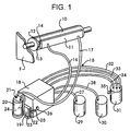
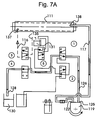
- the symbol F refers to the press frame.
- the numeral 10 designates generally an anilox roll rotatably mounted on the frame F.
- an ink fountain 11 equipped with doctor blades 12 and 13 along with suitable end seals, one of which is shown at 14.
- the fountain 11 is also mounted on the frame F and with the anilox roll 10 forms an ink chamber with a pair of ports for introducing and removing fluid.
- This much of the system is conventional and may take a variety of forms. Omitted for the sake of ease of presentation and clarity are the remaining press elements, viz., frame, central impression cylinder, plate cylinder, etc.
- the invention is used advantageously with the fluid system associated with the flexographic press and this is generally designated 15.
- the system 15 provides a first conduit 16 which is connected near the lower part of the fountain 11 and a second conduit 17 connected near the upper part of the fountain 11.
- the conduit 16 delivers ink to the fountain and the conduit 17 returns excess ink.
- the numeral 18 designates a cabinet operably associated with the frame F and which houses the valves, air cylinders and pump motor. In the illustration given it also supports the pump 19 and the ink pail 20.
- a suitable pump is Model No. 750-000 from Randolph Pump Co. located at Mancheca, Texas 78652.
- the return conduit 17 is connected to the pail 20 at 21 and the pump 19 has one port 22 coupled via conduit 23 to the pail 20 as at 24.
- the second port 25 of pump 19 is connected via conduit 26 to the interior of the housing 18, viz., to valves to be described hereinafter. These valves are also connected to the line 16.
- the housing 18 also has its valving connected via conduits 27 and 28 to container 29 and receiver 30 for fresh and waste solvent respectively.
- the housing 18 also is connected to once used solvent receiver or reservoir 31 by supply line 32 and return lines 33 and 34.
- the additional receiver 31 also has an air vent 35 for intake and exhaust of air.
- FIG. 2 illustrates the inking circuit. This shows the position of the valves and direction of pump rotation for normal printing. Ink is supplied to the doctor blade chamber and returns to the ink pail by gravity.
- ink from the pail 20 is drawn through conduit 23 to the port 22 of the pump 19.
- the ink is forced out of the port 25 into the conduit 26 where it is delivered to a three-way valve 1 .
- valve 1 After passing through one passage of the valve 1 , the ink flows via conduit 36 and, unlike in our earlier invention, by-passes the second three-way valve 2 . Instead, it flows via conduit 36 and through one passage of a third three-way valve 3.
- the output of valve 3 (as shown in FIG. 2) flows via conduit 16 to the lower port 37 of the ink fountain 11. Meanwhile, excess ink can flow out of the upper port 38 of the fountain 11 and via conduit 17 to the ink pail 20.
- the valves except 4 are advantageously ball valves of Model 70-000/900 Series of Conbraco Industries of Pageland, South Carolina and are equipped with air cylinders for rotating the balls thereof. For cleanup there has to be a change in the connection between the pump and ink pail to the pump and once-used solvent reservoir. This is illustrated relative to FIG. 3 in connection with the charging of once used solvent.
- FIG. 3 has to do with charging of solvent and it generally involves the press operator disconnecting the conduits 17 and 23 from the ink pail 20 and connecting them together as at 39 -- see the lower portion of FIG. 3. Alternatively, this can be achieved by suitable valving. All five of the valves are now employed -- in the condition represented in FIG. 3. This enables once used solvent -- from a previous cycle but relatively fresh -- to be pumped into the upper port 38 of the chamber to displace the ink remaining in the chamber 11 and line 16 and direct this unwanted ink to the waste receiver 30.
- Valves 1 and 4 are shifted from their first condition as shown in FIG. 2 so that when the pump 19 is operated in the reverse direction (see the arrow under the pump 19), once used solvent from the receiver 31 is drawn into the valves, hoses and doctor blade chamber.
- the pump 19 is rotated for a predetermined number of revolutions corresponding to the volume of the system and then stopped. Any excess volume of ink will be pumped directly into the waste receiver 30.
- the once used solvent is drawn from the receiver 31 into conduit 32, through the one passage of valve 5, and a previously selected passage of valve 2 through the other passage of valve 1 and then via conduit 26 into port 25 of pump 19.
- the reverse rotation of the pump 19 delivers this once used solvent out of port 22 and through lines 23 and 17 into the upper port 38 of fountain 11.
- Valve 4 is a two-way valve of Model 70-100/200 Series of the above Conbraco Industries.
- valves 1 and 4 are returned to their original state of inking (see FIG. 2) while the other three valves remain in their FIG. 5 condition.
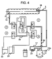
- a pump 19 is rotated in alternating forward and reverse directions for washing -- see the extreme lower right hand portion of FIG. 4.
- the rotational arrow is double ended to indicate this alternation. This can be done either manually or automatically by control means such as a Model PIC-90 motion controller made by Giddings & Lewis of Fond du Lac, Wisconsin.
- the means 19a for controlling the pump provides a rotation at maximum flow rate to increase the turbulence in the hoses, valves and doctor blade chamber.
- this rate is up to five times the normal ink flow rate and preferably three times.
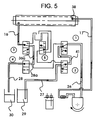
- the system is typically recharged as shown in FIG. 5 and the wash cycle FIG. 4 is repeated to provide a level of desired cleanliness (typically two wash cycles are adequate to allow changing to a new color ink).
- the closed circuit connects the ink pail lines 23 and 17 together allows flow rates which are much higher than are possible with the typical inking circuit. Flow rates are typically limited due to pressure limitations on a doctor blade chamber end seals, viz., the seal 14 of the upper left hand portion of FIG. 1. Because the closed circuit pulls the solvent out of the doctor blade chamber 11 at the same time that it pushes the solvent in, the pressure inside of the chamber stays very close to atmospheric and does not leak.
- the "twice used" solvent exits the chamber 11 via port 37 and in both instances flows through line 16, valve 3 , line 36a, line 28a, valve 4 and line 28 to waste receptacle 30.
- What is left in the system now is fresh solvent which is then used in a wash cycle as described in FIG. 6. After washing, this solvent will be directed to the additional receiver 31 in two convenient stages -- particularly when the chamber 11 is elevated so as to permit gravity draining. This is explained in conjunction with FIGS. 6 and 7.
- valve 3 has been changed from its FIG. 5 condition.
- the pump 19 is run in reverse -- compare FIG. 2. This draws air into the system from air port 35 and directs the once used solvent in the system into the receiver 31.
- the air flow is indicated by dotted lines.
- valve 5 is connected to the air port 35 in receiver 31 via line 32 and via lines 40, 41 and valves 1 and 2 are connected to conduit 26 connected to port 25 of pump 19.
- the output of pump 19 (in this orientation) is through port 22, lines 23 and 17 into the upper port 38 of the chamber 11. Concurrently, once used solvent flows out of the chamber 11 via port 37 into a conduit 16, valve 3, conduit 33, and receiver 31.
- FIG. 7 which is almost identical to FIG. 6 but with the exception that the pump is now rotated in the forward direction so as to introduce air into the bottom port 37 of fountain 11 rather than the top port 38.
- the second drain cycle is performed with the pump 19 running in the forward direction. In this way, nearly all of the solvent can be pumped out of the system prior to introducing the next batch of ink.
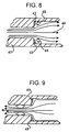
- FIGS. 8 and 9 illustrate advantageous features of the previously-disclosed invention.
- the flow is into a sudden enlargement. This illustrates the flow pattern at the inlet to the doctor blade chamber or at other abrupt changes and flow area.
- the flow of velocity over the "shadowed" surfaces is typically insufficient to clean away the ink solids.
- these shadowed areas are designated 42 and 43 and it will be seen that the velocity of flow is relatively low as indicated by the arrows 44 and 45 in contrast to the arrows 46 along the axis of the conduit 47.
- FIG. 9 shows a flow in a sudden contraction.
- An alternative embodiment provides a system without the solvent saver receiver and associated conduits and valve.
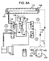
- FIG. 2 After inking is performed as seen in FIG. 2, the alternative embodiment performs, as the next step, that illustrated in FIG. 5 where the system is charged with fresh solvent. Thereafter, the washing step of FIG. 4 is performed. Following that, there are two drain steps -- here illustrated in FIGS. 6A and 7A. These differ essentially from FIGS. 6 and 7 in not using the solvent saver receiver 131 but instead in using the waste receiver 130, previously described in connection with FIG. 5.
- FIG. 6A it is seen generally that after the last wash cycle is complete, the balls in valves 1 and 4 are shifted and the pump 119 is run in reverse -- as designated by the clockwise directed arrow and opposite to the showing in FIG. 2 for inking. This draws air into the system from air vent 135 and expels the solvent in the system into the waste receiver 130. The air flow is indicated by dotted lines.
- valve 5 is connected via conduit 32 to the air vent 135 and as in FIG. 6 is connected to port 125 of pump 119.
- the output of pump 119 (in this orientation) is through port 122, lines 123 and 117 into the upper port 138 of the chamber 111.
- Ink flows out of the chamber 111 via port 137 into a conduit 116, valve 2, conduit 136a, conduit 128a, valve 4 and conduit 128 into the waste receiver 130.
- FIG. 7A is almost identical to FIG. 7 but with the exception that the waste liquid after leaving valve 1 goes to the waste receiver 130 rather than the receiver 131.
- Air is drawn into the system at 135 (upper left center), flows through conduit 133 through valve 3 and line 116 into port 137 of chamber 111. After flushing solvent out of the fountain 111, the air (now mixed with solvent) exits through port 138 and line 117 to the port 122 of pump 119. The mixture leaves through pump port 124, line 126 and valves 1 and 4 to conduit 128 and into receiver 130.
- the apparatus for washing the deck of a flexographic press as seen in FIG. 1 includes a frame F which rotatably supports an anilox roll 10.
- the roll 10 closes part of a relatively elongated ink chamber mounted on the frame F.
- the chamber has doctor blades 12, 13 and end seals as at 14 in contact with the anilox roll 10 to define a closed chamber.
- the chamber 11 has a pair of spaced apart ports 37, 38 adjacent the end seals in said chamber for introducing and removing fluid after the fluid has flowed through said chamber -- see FIG. 2.
- a reversible pump 19 is operably associated with the frame F and an ink source 20, a solvent source 29 or 31, and a waste receiver 30 are also operably associated with the frame F.
- the invention also includes conduits, i.e., fluid carrying pipes or hoses which connect the pump 19 with the ink source 20 as at 23 -- see FIG. 1.
- the pump 19 is also connected with the solvent source 29 as at 27, the solvent saver source 31 as at 32, the waste receiver 30 as at 28 and the fountain ports 37, 38 as at 16, 17 -- see also FIG. 3.
- a first function is to direct ink from the ink source 20 through the chamber 11 in a first condition of the valves. This is illustrated in FIG. 2 where the ink enters the pump 19 at port 22 from the ink pail 20 and conduit 23. The ink is pumped out of the pump 19 into lower port 37 of the chamber or fountain 11, through the fountain, out of upper port 38 via line 17 back to the ink pail 20.
- a second function is for directing solvent from the solvent source which may be the once used solvent reservoir 31 of FIG. 3 or the fresh solvent source 29 of FIG. 5 through the ink chamber in a second condition of the valves and while the pump 19 is disconnected from the ink source 20.
- a third function is to circulate solvent through the ink chamber by setting the valves in a third condition while the pump 19 is disconnected from the ink source 20 and both can be seen in FIG. 4 where a controller 19a on the pump 19 operates to reverse the pump direction a plurality of times to alternately introduce the solvent into one port 37, 38 and thereafter into the other port 38, 37.
- the hydraulic system generally designated S is now in the condition of a closed loop -- no fluid being taken in or discharged.
- a concluding step in the general operation or condition of the valve means 1 - 5 is directing the recycled solvent from the third function described above into the waste receiver 130 when the solvent saver is not employed. This is seen in FIGS. 6A and 7A where the exiting used solvent is replaced by air. This readies the system for charging with new ink.
- the preferred way of practicing the invention involves conserving the once used solvent for reuse -- after a different inking has occurred.
- the solvent source used initially is that of the reservoir 31 which contains "once used" solvent.
- the once used solvent is sent in a closed loop in the system orientation of FIG. 4 to provide "twice used" solvent (once for each of two different inks) which is then drained to the waste receiver 30.
- the fresh solvent is directed from the fresh solvent source 29 through the ink chamber 11 to force the previous solvent into the waste receiver 30 -- as in FIG. 5.
- the new solvent replaces the twice used solvent and is drained into the reservoir 31. This is done first as seen in FIG. 6 and thereafter as seen in FIG. 7. At this point the system (except for the reservoir 31) is generally free of solvent, containing only air.
Landscapes
- Inking, Control Or Cleaning Of Printing Machines (AREA)
- Cleaning By Liquid Or Steam (AREA)
Claims (14)
- Vorrichtung zum Waschen des Decks einer Flexographie-Druckmaschine mit einem Gestell (F), in dem eine Anilox-Walze (10) drehbar gelagert ist, einer im Gestell gehalterten relativ langgestreckten Farbkammer (11) mit Rakeln (12, 13) und Enddichtungen (14), die auf der Anilox-Walze aufliegen, um eine Kammer zu bilden, einem Paar beabstandeter Anschlüsse (37, 38) an den Enddichtungen der Kammer zum Zu- bzw. zum Abführen von Flüssigkeit nach dem Durchströmen der Kammer, einer betrieblich dem Gestell zugeordneten Umkehrpumpe (19), einer Druckfarbenquelle (20), einer Reinigungsmittelquelle (29, 31) und einem Abwasserbehälter (30), die ebenfalls dem Gestell betrieblich zugeordnet sind, einer Anordnung von Leitungen (16, 17, 23, 27, 28, 32 - 34, 36), die die Pumpe mit der Druckfarbenquelle, der Reinigungsmittelquelle, dem Abwasserbehälter und den Anschüssen (37, 38) verbinden, einer Anordnung von Ventilen (1 - 5), die betrieblich der Leitungsanordnung zugeordnet sind, um (a) in einem ersten Zustand der Ventilanordnung Druckfarbe von der Druckfarbenquelle (20) durch die Kammer (11) zuzuführen und (b) in einem zweiten Zustand der Ventilanordnung und bei von der Druckfarbenquelle abgetrennter Pumpe Reinigungsmittel aus der Reinigungsmittelquelle (29, 31) durch die Farbkammer zuzuführen, dadurch gekennzeichnet, daß die Kammer eine geschlossene Kammer ist, daß die Ventilanordnung betrieblich der Leitungsanordnung zugeordnet ist, um (c) in einem dritten Zustand der Ventilanordnung und bei von sowohl der Druckfarben- als auch der Reinigungsmittelquelle (20, 29, 31) abgetrennter Pumpe Reinigungsmittel durch die Farbkammer zu führen, und daß eine Einrichtung betrieblich der Pumpe zugeordnet ist, mit der im dritten Zustand diese mehrmals umschaltbar und in der Strömungsrichtung umkehrbar ist, um abwechselnd an einem Anschluß und dann am anderen Anschluß Reinigungsmittel zuzuführen, und (d) in einem vierten Zustand der Ventileinrichtung Reinigungsmittel aus (c) dem Abwasserbehälter (30, 130) zuzuführen.
- Vorrichtung nach Anspruch 2, bei der die Reinigungsmittelquelle (29, 31) ein Behälter (31) für einmal benutztes Reinigungsmittel ist und dem Rahmen betrieblich eine Quelle (29) frischen Reinigungsmittels zugeordnet ist, wobei die Ventilanordnung im Zustand (b) einmal benutztes Reinigungsmittel aus dem Behälter für einmal benutztes Reinigungsmittel durch die Farbkammer (11) führt und im Zustand (c) einmal benutztes Reinigungsmittel umlaufen läßt und frisches Reinigungsmittel aus der Quelle für frisches Reinigungsmittel zum Verdrängen von einmal benutztem Reinigungsmittel durch die Farbkammer und in den Behälter für einmal benutztes Reinigungsmittel führt.
- Vorrichtung nach Anspruch 1, bei dem die Reinigungsmittelquelle eine Quelle (29) von frischem Reinigungsmittel ist.
- Vorrichtung nach Anspruch 1, bei dem in einem Drehzustand der Pumpe (19) mittels der Ventilanordnung betrieblich Luft an einem Anschluß (37) und im umgekehrten Drehzustand der Pumpe (19) am anderen Anschluß (38) der Farbkammer zuführbar ist.
- Vorrichtung nach Anspruch 1, bei der die Reinigungsmittelquelle (29, 31) eine Quelle (29) von frischem Reinigungsmittel und einen Behälter (31) mit einmal benutztem Reinigungsmittel aufweist und bei der die Druckmaschine weiterhin mit einer Luftanschlußeinrichtung (35) versehen ist, die betrieblich dem Gestell zugeordnet ist, und die Leitungsanordnung auch die Pumpe mit dem Luftanschluß verbindet, wobei die Ventilanordnung auch(b) in einem zweiten Zustand und bei von der Druckfarbquelle und der Quelle frischen Reinigungsmittels getrennter Pumpe einmal benutztes Reinigungsmittel aus dem Behälter durch die Farbkammer führt, um im System verbliebene Druckfarbe zum Abwasserbehälter abzuleiten,(c) im dritten Zustand und bei von der Farbquelle, der Quelle frischen Reinigungsmittels, vom Behälter für einmal benutztes Reinigungsmittel und dem Abwasserbehälter getrennter Pumpe einmal benutztes Reinigungsmittel durch die Farbkammer führt, wobei mittels einer der Pumpe betrieblich zugeordneten Einrichtung die Strömungsrichtung in dieser und ihre Pumprichtung mehrmals umkehrbar sind, um Reinigungsmittel abwechselnd an einem und dann am anderen Anschluß einzuspeisen, wobei einmal benutztes Reinigungsmittel zu Abwasser umgewandelt wird,(d) in einem vierten Zustand frisches Reinigungsmittel aus der Quelle frischen Reinigungsmittels durch die Farbkammer führt, um das frische Reinigungsmittel zu weiterem einmal benutztem Reinigungsmittel umzuwandeln, während sie das Abwasser in den Abwasserbehälter leitet, und(e) in einem fünften Zustand das weitere einmal benutzte Reinigungsmittel in den Behälter für einmal benutztes Reinigungsmittel leitet, während sie Luft an der Luftanschlußeinrichtung zuführt.
- Vorrichtung nach Anspruch 5, bei der die Leitungsanordnung einen ersten Leitungsteil (17, 39, 23, 26, 32), der einen ersten (38) der Anschlüsse mit dem Behälter (31) für einmal benutztes Reinigungsmittel verbindet, und einen zweiten Leitungsteil (16, 28) aufweist, der einen zweiten (37) der Anschlüsse mit dem Abwasserbehälter (30) verbindet.
- Vorrichtung nach Anspruch 5, bei der die Luftanschlußeinrichtung (35) betrieblich dem Behälter (31) für einmal benutztes Reinigungsmittel zugeordnet ist.
- Vorrichtung nach Anspruch 1, bei der die Ventilanordnung (d) auch Luft von der Luftanschlußeinrichtung (35) her in die Leitungsanordnung einspeist.
- Verfahren zum Waschen des Decks einer Flexographie-Druckmaschine mit einem System (15) mit einer verhältnismäßig langgestreckten Farbkammer (11) mit einem Anschluß (37, 38) an jedem Ende, einer Druckfarbenquelle (20), einer Quelle (29, 31) eines Reinigungsmittels, einem Behälter (30) für benutztes Reinigungsmittel, einer Umkehrpumpe (19) und einer Leitungsanordnung (16, 17, 23, 27, 28, 32 - 34, 36), die die Farbkammer, die Druckfarbenquelle, die Pumpe, die Reinigungsmittelquelle und den Behälter für benutztes Reinigungsmittel miteinander verbindet, dadurch gekennzeichnet,
daß man eine geschlossene Kammer vorsieht und dieser Druckfarbe aus der Druckfarbenquelle für eine vorbestimmte Dauer zuführt, nach dem Abbruch der Druckfarbenzufuhr Reinigungsmittel aus der Reinigungsmittelquelle in die Farbkammer, die Pumpe und die Leitungsanordnung einspeist, die Pumpe von der Reinigungsmittelquelle abtrennt und einen geschlossenen Reinigungsmittel-Kreislauf (23, 17, 16, 36, 26) zwischen der Pumpe und den Anschlüssen zur Farbkammer herstellt, Reinigungsmittel in dem geschlossenen Kreislauf umlaufen läßt, während man die Richtung der Strömung durch die Farbkammer hin- und herschaltet, und danach Reinigungsmittel aus der Farbkammer abläßt. - Verfahren nach Anspruch 9, bei dem während des Hin- und Herpumpens die Strömung etwa fünfmal höher ist als der Druckfarbenumlauf.
- Verfahren nach Anspruch 9, bei dem man einen Behälter (31) für einmal benutztes Reinigungsmittel vorsieht, im Einführschritt einmal benutztes Reinigungsmittel aus dem Behälter einspeist, im Pumpschritt einmal benutztes Reinigungsmittel im geschlossenen Kreislauf umlaufen läßt und im Abführschritt das durch das System gepumpte Reinigungsmittel abläßt, während man es durch frisches Reinigungsmittel ersetzt.
- Verfahren nach Anspruch 11, bei dem man Luft in das System einspeist, während man Austausch-Reinigungsmittel in den Behälter leitet.
- Verfahren nach Anspruch 12, bei dem man zur Zufuhr von Luft diese in einem Drehzustand der Pumpe in einen Anschluß (37) und in einem anderen Drehzustand der Pumpe in den anderen Anschluß (38) der Farbkammer einspeist.
- Verfahren nach Anspruch 9, bei dem man im Einführschritt frisches Reinigungsmittel aus der Reinigungsmittelquelle einspeist und im Abführschritt umlaufendes Reinigungsmittel abführt, während man Luft in die Farbkammer einspeist.
Applications Claiming Priority (4)
| Application Number | Priority Date | Filing Date | Title |
|---|---|---|---|
| US14546093A | 1993-10-29 | 1993-10-29 | |
| US145460 | 1993-10-29 | ||
| US274999 | 1994-07-13 | ||
| US08/274,999 US5402724A (en) | 1993-10-29 | 1994-07-13 | Method and apparatus for washing the deck of a press or coater |
Publications (2)
| Publication Number | Publication Date |
|---|---|
| EP0650834A1 EP0650834A1 (de) | 1995-05-03 |
| EP0650834B1 true EP0650834B1 (de) | 1998-03-18 |
Family
ID=26843006
Family Applications (1)
| Application Number | Title | Priority Date | Filing Date |
|---|---|---|---|
| EP94116024A Expired - Lifetime EP0650834B1 (de) | 1993-10-29 | 1994-10-11 | Vorrichtung und Verfahren zum Reinigen der Farbvorrichtung einer Druckmaschine oder Lackierer |
Country Status (5)
| Country | Link |
|---|---|
| US (1) | US5402724A (de) |
| EP (1) | EP0650834B1 (de) |
| CA (1) | CA2117835A1 (de) |
| DE (1) | DE69409060T2 (de) |
| ES (1) | ES2117184T3 (de) |
Families Citing this family (25)
| Publication number | Priority date | Publication date | Assignee | Title |
|---|---|---|---|---|
| US5575211A (en) * | 1994-10-28 | 1996-11-19 | Hycorr Machine Corporation | Washing Arrangement for rotary printer |
| US5603263A (en) * | 1995-09-08 | 1997-02-18 | Heidelberger Druckmaschinen Ag | Scraper blade and ink scavenger for printing presses |
| DE19536268C1 (de) * | 1995-09-28 | 1997-02-06 | Windmoeller & Hoelscher | Rakelvorrichtung für ein Spülfarbwerk einer Rotationsdruckmaschine |
| NL1001398C2 (nl) * | 1995-10-11 | 1997-04-15 | Stork Brabant Bv | Reinigingsinrichting voor gebruik bij het reinigen van een pastatoevoer- systeem van een rotatiezeefdrukmachine. |
| DE19546972A1 (de) * | 1995-12-15 | 1997-06-19 | Baldwin Gegenheimer Gmbh | Waschanlage einer Maschine der graphischen Industrie |
| DE19548535C2 (de) * | 1995-12-22 | 1999-12-30 | Windmoeller & Hoelscher | Verfahren und Vorrichtung zur Reinigung einer Rakelvorrichtung für ein Spülfarbwerk einer Rotationsdruckmaschine |
| DE29616686U1 (de) * | 1996-09-25 | 1996-11-14 | MAN Roland Druckmaschinen AG, 63075 Offenbach | Einrichtung zum Beschichten von Bedruckstoffen mit einer Flüssigkeit |
| DK173668B1 (da) * | 1997-03-24 | 2001-06-05 | Tresu As | Fremgangsmåde samt pumpeunit til forsyning af et trykværk med farve og rensevæske |
| EP0951998B1 (de) * | 1998-04-23 | 2003-07-09 | Umetani Mfg.Co.,Ltd. | Druckmaschine für Bogen aus Wellpappe und Verfahren zum Reinigen des Farbkastens der Maschine |
| US6576059B2 (en) * | 1999-11-22 | 2003-06-10 | Harris & Bruno Company, Inc. | Chambered doctor blade system for water-based and UV-based coatings |
| US6254363B1 (en) | 2000-01-20 | 2001-07-03 | M. A. Hannacolor, A Division Of M. A. Hanna Company | Liquid colorant tube assembly |
| DE10209856B4 (de) * | 2002-03-06 | 2007-09-20 | Man Roland Druckmaschinen Ag | Verfahren zur Steuerung der Einbringung von Reinigungsflüssigkeit |
| ITGE20020033A1 (it) * | 2002-04-24 | 2003-10-24 | Schiavi Spa | Metodo di lavaggio automatico del circuito di inchiostrazione nelle macchine da stampa rotative, ed impianto per l'attuazione di detto metod |
| JP4355586B2 (ja) * | 2004-02-12 | 2009-11-04 | キヤノン株式会社 | 液体塗布装置およびインクジェット記録装置 |
| US7600471B2 (en) * | 2005-05-10 | 2009-10-13 | Westby Ronald K | Hand proofer tool |
| US20060260488A1 (en) * | 2005-05-10 | 2006-11-23 | Westby Ronald K | Ink proofer cleaning system |
| US8720335B2 (en) * | 2007-04-24 | 2014-05-13 | Probity Engineering, Llc | Offset hand proofer tool |
| US8973497B2 (en) | 2007-04-24 | 2015-03-10 | Probity Engineering, Llc | Flexographic proofing tools and methods |
| ES2323215B1 (es) | 2007-11-19 | 2010-04-23 | Enviroxi S.L. | Metodo de limpieza de un dispositivo de rasquetas. |
| JP5529497B2 (ja) * | 2009-11-05 | 2014-06-25 | 三菱重工印刷紙工機械株式会社 | フレキソ印刷機のインキ洗浄方法及び装置 |
| CN102501595B (zh) * | 2011-11-23 | 2014-07-02 | 贵州劲嘉新型包装材料有限公司 | 一种凹印机网纹辊循环喷射清洗系统 |
| DE102012103851A1 (de) * | 2012-05-02 | 2013-11-21 | Windmöller & Hölscher Kg | Verfahren zum Reinigen eines Farbsystems einer Rotationsdruckmaschine sowie Farbsystem |
| US20140216502A1 (en) * | 2013-02-05 | 2014-08-07 | Ecochem Australia Pty Ltd | System and method for automatically cleaning converters |
| JP5701364B1 (ja) * | 2013-11-05 | 2015-04-15 | 三菱重工印刷紙工機械株式会社 | フレキソ印刷機のインキ洗浄装置及びインキ洗浄方法 |
| CN116787927B (zh) * | 2023-08-15 | 2023-11-21 | 广东东方精工科技股份有限公司 | 一种纸板印刷机的刮刀供墨装置 |
Family Cites Families (8)
| Publication number | Priority date | Publication date | Assignee | Title |
|---|---|---|---|---|
| US3800702A (en) * | 1972-12-07 | 1974-04-02 | S & S Corrugated Paper Mach | Inking apparatus having automatic wash-up means |
| DE3005236C2 (de) * | 1980-02-13 | 1983-05-19 | Mathias Bäuerle GmbH, 7742 St Georgen | Waschwerk für eine Offsetmaschine |
| US4369734A (en) * | 1980-03-17 | 1983-01-25 | M.A.N.-Roland Druckmaschinen Aktiengesellschaft | Varnishing assembly in a printing press having self-cleaning feature |
| EP0186193B1 (de) * | 1984-12-26 | 1990-12-12 | Dai Nippon Insatsu Kabushiki Kaisha | Tiefdrucksystem |
| US4686902A (en) * | 1986-10-31 | 1987-08-18 | Precision Engineered Systems Inc. | Automatic blanket wash system |
| JPH01253788A (ja) * | 1988-04-04 | 1989-10-11 | Canon Inc | 画像パターン入出力装置 |
| US5109770A (en) * | 1989-09-22 | 1992-05-05 | Oxy-Dry Corporation | Printing cylinder cleaning system |
| US5213044A (en) * | 1990-11-30 | 1993-05-25 | Como Technologies, Incorporated | Method and apparatus for use in printing |
-
1994
- 1994-07-13 US US08/274,999 patent/US5402724A/en not_active Expired - Lifetime
- 1994-10-11 ES ES94116024T patent/ES2117184T3/es not_active Expired - Lifetime
- 1994-10-11 CA CA002117835A patent/CA2117835A1/en not_active Abandoned
- 1994-10-11 DE DE69409060T patent/DE69409060T2/de not_active Expired - Fee Related
- 1994-10-11 EP EP94116024A patent/EP0650834B1/de not_active Expired - Lifetime
Also Published As
| Publication number | Publication date |
|---|---|
| CA2117835A1 (en) | 1995-04-30 |
| DE69409060D1 (de) | 1998-04-23 |
| US5402724A (en) | 1995-04-04 |
| EP0650834A1 (de) | 1995-05-03 |
| DE69409060T2 (de) | 1998-07-02 |
| ES2117184T3 (es) | 1998-08-01 |
Similar Documents
| Publication | Publication Date | Title |
|---|---|---|
| EP0650834B1 (de) | Vorrichtung und Verfahren zum Reinigen der Farbvorrichtung einer Druckmaschine oder Lackierer | |
| US3800702A (en) | Inking apparatus having automatic wash-up means | |
| CA2097378C (en) | Automatic coating circulation and wash-up system for printing presses | |
| US5003876A (en) | Printing apparatus with dual inking system | |
| CN1078533C (zh) | 轮转印刷机油墨机组刮墨装置的清洗方法和设备 | |
| US5683508A (en) | Coating apparatus and method for dispensing a liquid, and draining and cleaning a coating apparatus | |
| JPH11320848A (ja) | 小室を有するドクタ―ブレ―ドのためのインク/洗浄液供給装置 | |
| US6576059B2 (en) | Chambered doctor blade system for water-based and UV-based coatings | |
| EP1497130B2 (de) | Verfahren zum automatischen waschen von dem tintenkreis in rotationsdruckmaschinen, und anlage zur durchführung des verfahrens | |
| KR20010005688A (ko) | 인쇄유니트에 인쇄잉크와 세척액을 공급하는 방법과 펌프유니트 | |
| JP3392548B2 (ja) | 印刷機あるいは塗工機のデッキを洗浄するための装置と方法 | |
| CN112223907B (zh) | 一种全自动供墨和清洗的墨站 | |
| US3025863A (en) | Ink pump cleaning device | |
| CN219252279U (zh) | 一种印染布料调色机 | |
| CN1122280A (zh) | 旋转印刷机上墨元件的清洗装置 | |
| US20030188771A1 (en) | Radiator cleaning device | |
| JP2502903Y2 (ja) | 導電性塗料の静電塗装装置 | |
| JP3718048B2 (ja) | 塗装用ギアポンプ | |
| JP3472295B1 (ja) | 製函印刷機のインクローラのインク循環供給装置 | |
| CN222250060U (zh) | 污水处理设备 | |
| CN220758828U (zh) | 一种彩印用颜料调配装置 | |
| CN223774878U (zh) | 一种电热恒温水浴箱 | |
| CN222490773U (zh) | 一种自动化灌胶设备 | |
| JPS61144354A (ja) | 印刷機におけるロ−ラ洗浄装置 | |
| JPH0623594Y2 (ja) | 自動調液装置 |
Legal Events
| Date | Code | Title | Description |
|---|---|---|---|
| PUAI | Public reference made under article 153(3) epc to a published international application that has entered the european phase |
Free format text: ORIGINAL CODE: 0009012 |
|
| AK | Designated contracting states |
Kind code of ref document: A1 Designated state(s): DE ES FR GB IT SE |
|
| 17P | Request for examination filed |
Effective date: 19951002 |
|
| 17Q | First examination report despatched |
Effective date: 19961126 |
|
| GRAG | Despatch of communication of intention to grant |
Free format text: ORIGINAL CODE: EPIDOS AGRA |
|
| GRAG | Despatch of communication of intention to grant |
Free format text: ORIGINAL CODE: EPIDOS AGRA |
|
| GRAH | Despatch of communication of intention to grant a patent |
Free format text: ORIGINAL CODE: EPIDOS IGRA |
|
| GRAH | Despatch of communication of intention to grant a patent |
Free format text: ORIGINAL CODE: EPIDOS IGRA |
|
| GRAA | (expected) grant |
Free format text: ORIGINAL CODE: 0009210 |
|
| AK | Designated contracting states |
Kind code of ref document: B1 Designated state(s): DE ES FR GB IT SE |
|
| REF | Corresponds to: |
Ref document number: 69409060 Country of ref document: DE Date of ref document: 19980423 |
|
| ITF | It: translation for a ep patent filed | ||
| ET | Fr: translation filed | ||
| REG | Reference to a national code |
Ref country code: ES Ref legal event code: FG2A Ref document number: 2117184 Country of ref document: ES Kind code of ref document: T3 |
|
| PLBE | No opposition filed within time limit |
Free format text: ORIGINAL CODE: 0009261 |
|
| STAA | Information on the status of an ep patent application or granted ep patent |
Free format text: STATUS: NO OPPOSITION FILED WITHIN TIME LIMIT |
|
| 26N | No opposition filed | ||
| REG | Reference to a national code |
Ref country code: GB Ref legal event code: IF02 |
|
| PGFP | Annual fee paid to national office [announced via postgrant information from national office to epo] |
Ref country code: FR Payment date: 20030915 Year of fee payment: 10 |
|
| PGFP | Annual fee paid to national office [announced via postgrant information from national office to epo] |
Ref country code: SE Payment date: 20030925 Year of fee payment: 10 |
|
| PG25 | Lapsed in a contracting state [announced via postgrant information from national office to epo] |
Ref country code: SE Free format text: LAPSE BECAUSE OF NON-PAYMENT OF DUE FEES Effective date: 20041012 |
|
| EUG | Se: european patent has lapsed | ||
| PG25 | Lapsed in a contracting state [announced via postgrant information from national office to epo] |
Ref country code: FR Free format text: LAPSE BECAUSE OF NON-PAYMENT OF DUE FEES Effective date: 20050630 |
|
| REG | Reference to a national code |
Ref country code: FR Ref legal event code: ST |
|
| PGFP | Annual fee paid to national office [announced via postgrant information from national office to epo] |
Ref country code: GB Payment date: 20050926 Year of fee payment: 12 Ref country code: DE Payment date: 20050926 Year of fee payment: 12 |
|
| PGFP | Annual fee paid to national office [announced via postgrant information from national office to epo] |
Ref country code: ES Payment date: 20051025 Year of fee payment: 12 |
|
| PGFP | Annual fee paid to national office [announced via postgrant information from national office to epo] |
Ref country code: IT Payment date: 20061031 Year of fee payment: 13 |
|
| PG25 | Lapsed in a contracting state [announced via postgrant information from national office to epo] |
Ref country code: DE Free format text: LAPSE BECAUSE OF NON-PAYMENT OF DUE FEES Effective date: 20070501 |
|
| GBPC | Gb: european patent ceased through non-payment of renewal fee |
Effective date: 20061011 |
|
| PG25 | Lapsed in a contracting state [announced via postgrant information from national office to epo] |
Ref country code: GB Free format text: LAPSE BECAUSE OF NON-PAYMENT OF DUE FEES Effective date: 20061011 |
|
| REG | Reference to a national code |
Ref country code: ES Ref legal event code: FD2A Effective date: 20061013 |
|
| PG25 | Lapsed in a contracting state [announced via postgrant information from national office to epo] |
Ref country code: ES Free format text: LAPSE BECAUSE OF NON-PAYMENT OF DUE FEES Effective date: 20061013 |
|
| PG25 | Lapsed in a contracting state [announced via postgrant information from national office to epo] |
Ref country code: IT Free format text: LAPSE BECAUSE OF NON-PAYMENT OF DUE FEES Effective date: 20071011 |