EP0649255A2 - Gerät zur Wiedergabe eines Videosignals - Google Patents
Gerät zur Wiedergabe eines Videosignals Download PDFInfo
- Publication number
- EP0649255A2 EP0649255A2 EP94307624A EP94307624A EP0649255A2 EP 0649255 A2 EP0649255 A2 EP 0649255A2 EP 94307624 A EP94307624 A EP 94307624A EP 94307624 A EP94307624 A EP 94307624A EP 0649255 A2 EP0649255 A2 EP 0649255A2
- Authority
- EP
- European Patent Office
- Prior art keywords
- frames
- video signal
- read
- data
- fields
- Prior art date
- Legal status (The legal status is an assumption and is not a legal conclusion. Google has not performed a legal analysis and makes no representation as to the accuracy of the status listed.)
- Granted
Links
Images


Classifications
-
- H—ELECTRICITY
- H04—ELECTRIC COMMUNICATION TECHNIQUE
- H04N—PICTORIAL COMMUNICATION, e.g. TELEVISION
- H04N5/00—Details of television systems
- H04N5/76—Television signal recording
-
- G—PHYSICS
- G11—INFORMATION STORAGE
- G11B—INFORMATION STORAGE BASED ON RELATIVE MOVEMENT BETWEEN RECORD CARRIER AND TRANSDUCER
- G11B27/00—Editing; Indexing; Addressing; Timing or synchronising; Monitoring; Measuring tape travel
- G11B27/005—Reproducing at a different information rate from the information rate of recording
-
- H—ELECTRICITY
- H04—ELECTRIC COMMUNICATION TECHNIQUE
- H04N—PICTORIAL COMMUNICATION, e.g. TELEVISION
- H04N5/00—Details of television systems
- H04N5/76—Television signal recording
- H04N5/91—Television signal processing therefor
- H04N5/92—Transformation of the television signal for recording, e.g. modulation, frequency changing; Inverse transformation for playback
- H04N5/926—Transformation of the television signal for recording, e.g. modulation, frequency changing; Inverse transformation for playback by pulse code modulation
-
- H—ELECTRICITY
- H04—ELECTRIC COMMUNICATION TECHNIQUE
- H04N—PICTORIAL COMMUNICATION, e.g. TELEVISION
- H04N5/00—Details of television systems
- H04N5/76—Television signal recording
- H04N5/78—Television signal recording using magnetic recording
- H04N5/782—Television signal recording using magnetic recording on tape
- H04N5/783—Adaptations for reproducing at a rate different from the recording rate
-
- H—ELECTRICITY
- H04—ELECTRIC COMMUNICATION TECHNIQUE
- H04N—PICTORIAL COMMUNICATION, e.g. TELEVISION
- H04N5/00—Details of television systems
- H04N5/76—Television signal recording
- H04N5/91—Television signal processing therefor
- H04N5/93—Regeneration of the television signal or of selected parts thereof
- H04N5/937—Regeneration of the television signal or of selected parts thereof by assembling picture element blocks in an intermediate store
Definitions
- This invention relates to video signal reproducing apparatus. More particularly, but not exclusively, the invention relates to apparatus for reproducing a video signal at high speed from a storage medium such as a video disk, a hard disk, and a semiconductor memory permitting random access.
- a storage medium such as a video disk, a hard disk, and a semiconductor memory permitting random access.
- a video disk system for example a laser disk system
- one frame of a video signal is recorded in each rotation of the disk in the case of CAV disks and one to three frames of video signal are recorded in each rotation of the disk in the case of CLV disks.
- a video disk system for example a laser disk system
- one frame of a video signal is recorded in each rotation of the disk in the case of CAV disks and one to three frames of video signal are recorded in each rotation of the disk in the case of CLV disks.
- A is an integer equal to 2 or above
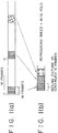
- the practice is successively to display one frame at intervals of A frames as shown in FIGs. 14(a) and 14(b) of the accompanying drawings. More specifically, such an operation is repeated that, after one frame has been read from a video disk, the read head is moved to the track located A frames rearward during, generally, a vertical blanking period, and the next video signal is read therefrom.
- a video signal reproducing apparatus comprising means for reading a video signal from a storage medium, and means for outputting the read video signal to display means, such that continued N frames or N fields at intervals of M frames or M fields (where M and N are integers satisfying M > N > 1) of a video signal are output to the display means.
- M/N-fold high-speed reproduction can be achieved.
- a video signal reproducing apparatus such that, when high-speed reproduction in the reverse direction is performed therein, N frames or N fields of a video signal are read in the forward direction and the read video signal is output to the display means in the forward direction.
- images of continued N frames or N fields at intervals of M frames or M fields are displayed in the forward direction.
- images of frames or fields 2000, 2001, 2002, ..., 2018, 2019, 1000, 1001, 1002, ..., 1018, 1019, 0, 1, 2, ..., 18, 19, « are displayed.
- a video signal reproducing apparatus comprising means for reading a video signal from a storage medium, and means for outputting the read video signal to display means, such that L frames or L fields as part of continued N frames or N fields at intervals of M frames or M fields (where L, M, and N are integers satisfying M > N > L > 1) of a video signal are output to the display means.
- An embodiment of the invention described hereinbelow seeks to solve the problems mentioned above.
- the embodiment seeks to provide a video signal reproducing apparatus which is capable of reproducing picture images with good continuity between frames and the content of which is easy to grasp, and which makes accurate high-speed searching possible.
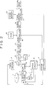
- FIG. 2 is a block diagram showing a structure of a video signal reproducing apparatus in which the invention is embodied.
- video data obtained by A/D converting a video signal and compressing the same for data on the MPEG system or the like is recorded.
- a spindle motor 2 rotates the video disk 1 at a predetermined rotational speed.
- An optical head 3 throws a laser beam from a semiconductor laser incorporated therein on the video disk 1 and reads data recorded therein.
- the semiconductor laser in the optical head 3 is driven by a laser driver 4.
- the optical head 3 is structured to be slid in the radial direction of the video disk 1 by a slide motor 5.
- a video signal reproduced from the optical head 3 is amplified by an RF amplifier 8 and supplied to a servo circuit 6 and an equalizer 9.
- the servo circuit 6 produces a tracking control signal, a focus control signal, and a spindle control signal from the output of the RF amplifier 8 and supplies the signals to the optical head 3 and the spindle motor 2.
- the servo circuit 6, further, supplies a control signal for controlling the slide motor 5 at the time of high-speed reproduction and random access.
- the laser driver 4 and the servo circuit 6 are controlled by a system controller 7.
- the system controller 7 is formed of a microcomputer and executes control of the whole apparatus.
- the equalizer 9 equalizes the output waveform of the RF amplifier 8 and supplies its output to a detector circuit 10 and a PLL circuit 11.
- the PLL circuit 11 extracts a clock signal on the basis of the output from the equalizer 9 and supplies the clock signal to the detector circuit 10.
- the detector circuit 10, on the basis of the clock signal, converts input data to binary data changing between two values of 0 and 1.
- the output of the detector circuit 10 is supplied to a channel decoder 12 and, therein, demodulation of the modulated record is performed, and the output therefrom is supplied to an ECC decoder 13.
- the ECC decoder 13 performs error correction of the video data using an error correcting code added to the video data and outputs the corrected data to a RAM controller 14.
- the RAM controller 14 temporarily stores the output of the ECC decoder 13 into a RAM 15 and reads the data from the same to thereby absorb the difference between the rate of data reading from the video disk 1 and the processing rate in a source decoder 16.
- the source decoder 16 decodes the video data compressed for data on the MPEG system or the like and supplies the decoded data to a frame memory controller 17.
- the frame memory controller 17 stores the video data into a frame memory 18 and reads the data to output image data.
- the image data output from the frame memory is A/D converted and output to a display unit (not shown) to be displayed as a picture image.
- FIGs. 1(a) and 1(b) are diagrams showing the basic operation made in the forward reproduction.
- high-speed reproduction at M/N-fold speed is achieved by displaying continued N frames at intervals of M frames, where M and N are integers satisfying the relationship M > N > 1.
- the values of M and N need not be fixed values but may be variable.
- the order of the reproduced frames are as follows: 0, 1, 2, ..., N-1, M, M + 1, M + 2, ..., M + N -1, 2M, 2M + 1, 2M + 2, ..., 2M + N - 1, 3M, 3M + 1, 3M + 2, ..., 3M + N - 1, ......
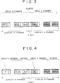
- the reading and the displaying of the video data are performed at the timing shown in FIG. 3. Namely, N frames of video data are read from the video disk 1 and then the N frames of video data are displayed.
- the optical head 3 is caused to move to the track where the data to be read next is present by drive of the slide motor 5 or movement of the optical head 3 itself so that it can read the video data.
- the access period must be within the vertical blanking period.
- the reading and the displaying of the video data are performed at the timing shown in FIG. 4.
- Such a state is brought about when for example the rate of reading data from the video disk 1 is larger than the rate of displaying the data. Since the system of FIG. 2 is structured so as to reproduce a video disk 1 in which video data compressed for data is recorded, the described state is generally brought about. Even when the system is such that is structured to reproduce a video disk with uncompressed video data recorded therein, the time for reading data becomes shorter than the time for displaying the data if the number of revolutions of the video disk is set higher.
- the access period can be made longer than the vertical blanking period.
- the access time becomes longer because a long time is required for locking the phase after the track jump.
- the access period can be made longer in the present system, it becomes possible to cope with the high-speed reproduction of a CLV disk without using a frame memory.
- the access period d can be prolonged by increasing the value of the number of continued frames N to be displayed.
- the last frame (the frame to which a suffix N - 1 is attached in FIG. 4) is continually displayed until next data is read.
- the data may be repeatedly read and output to the display unit.
- continued N frames are displayed at intervals of M frames the same as in the forward reproduction.
- two systems are possible: one in which the continued N frames are reproduced in the reverse direction and the other in which they are reproduced in the forward direction.
- the order of the displayed frames in each system is as follows:
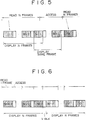
- reading and displaying of video data are performed at the timing shown in FIG. 6. More specifically, data is read at intervals of one frame and, when reading of one frame is finished, the optical head 3 is caused to move to the track where the data to be read next is recorded so that it can read the data. This access period must be within the vertical blanking period.
- This is an example of the system in which the continued N frames are reproduced in the reverse direction. Such reading and displaying can be achieved only when the video data is not compressed or the compression system is that performed within the frame.
- motion compensated coding is performed as in the MPEG system, decoding in the reverse direction is impossible and, hence, such reproduction in the reverse direction of continued N frames cannot be achieved.
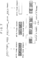
- FIG. 7 shows an example of the system in which continued N frames are reproduced in the reverse direction.
- the data necessary for displaying N frames are read from the video disk 1 in the forward direction and, when the reading of the N frames has been finished, the track where data to be read next is present is accessed.
- the data read are decoded by the source decoder 16 and written into the frame memory 18.
- the data are read in the order reverse to the order in which the data were written and output to the display unit.
- the frame memory 18 is required to have N-frame capacity, video data are input to the source decoder 16 in the forward direction. Therefore, even if the data compressing system is such as the MPEG system in which motion compensation is made, this method can be achieved. Although the time for reading necessary data for displaying N frames and the time for writing the data into the frame memory 18 is equal in the case of FIG. 7, this can be attained by increasing the speed of the write clock of the frame memory controller 17.
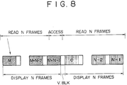
- FIG. 8 is an example of the system in which continued N frames are reproduced in the forward direction.
- N frames of data are read in the forward direction and, when the reading has been finished, the operation to access the track where the data to be read next is recorded is performed the same as in FIG. 7.
- the video data decoded by the source decoder 16 are not stored in the frame memory 18 for reversing the order but they are output to the display unit as they are.
- the time interval between each of the N-frame data becomes larger as the value of M is increased. Therefore, a reproduced image not looking strange can be obtained even if the continued N frames are not reproduced in the reverse order. Further, it is possible to eliminate the frame memory 18.
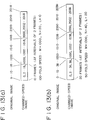
- FIGs. 9(a) and 9(b) are diagrams explanatory of the basic operation in the system in which L frames within continued N frames at intervals of M frames are reproduced and, thereby, M/L-fold high-speed reproduction is achieved.
- M, N, and L are integers satisfying M > N > L > 1. It is necessary that the L frames are split into at least two portions within the N frames as shown in FIG. 9(b).
- N-frame data may be read in succession and only necessary portion thereof may be decoded and displayed.
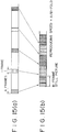
- two systems are applicable as in the case described in [2](b), i.e., one system in which L frames are reproduced in the forward direction and the other system in which the L frames are reproduced in the reverse direction. Operation performed in the system in which reproduction is made in the reverse direction is shown in FIG. 10. In this case, only L-frame capacity is required as the capacity of the memory for reversing the order of frames read from the video disk, and therefore the memory can be made smaller than that used in the case of [2](b).
- the above embodiment was described as a system reproducing a digital video disk in which video data compressed on the MPEG system or the like is recorded, the invention can be applied also to a system reproducing a video disk in which an analog video signal is recorded such as the conventional laser disk system. It can further be applied to the recording and reproducing system of the digital video disk, the system recording/reproducing a video signal on the hard disk, and the system writing/reading a video signal on a semiconductor memory.
- a video signal has been described to be read and displayed in units of frames
- the system may be structured such that a video signal is read and displayed in units of fields.
Applications Claiming Priority (3)
| Application Number | Priority Date | Filing Date | Title |
|---|---|---|---|
| JP28403493 | 1993-10-18 | ||
| JP5284034A JPH07115619A (ja) | 1993-10-18 | 1993-10-18 | ビデオ信号再生装置 |
| JP284034/93 | 1993-10-18 |
Publications (3)
| Publication Number | Publication Date |
|---|---|
| EP0649255A2 true EP0649255A2 (de) | 1995-04-19 |
| EP0649255A3 EP0649255A3 (de) | 1996-02-07 |
| EP0649255B1 EP0649255B1 (de) | 1999-08-11 |
Family
ID=17673449
Family Applications (1)
| Application Number | Title | Priority Date | Filing Date |
|---|---|---|---|
| EP94307624A Expired - Lifetime EP0649255B1 (de) | 1993-10-18 | 1994-10-18 | Gerät zur Wiedergabe eines Videosignals |
Country Status (8)
| Country | Link |
|---|---|
| US (1) | US5784518A (de) |
| EP (1) | EP0649255B1 (de) |
| JP (1) | JPH07115619A (de) |
| KR (1) | KR950013240A (de) |
| CN (1) | CN1108842A (de) |
| DE (1) | DE69420002T2 (de) |
| MY (1) | MY113974A (de) |
| TW (1) | TW303134U (de) |
Cited By (4)
| Publication number | Priority date | Publication date | Assignee | Title |
|---|---|---|---|---|
| EP1005225A2 (de) * | 1998-11-27 | 2000-05-31 | Matsushita Electric Industrial Co., Ltd. | Dekodierungsgerät und Dekodierungsverfahren mit Rückwärtswiedergabe |
| EP1104188A2 (de) * | 1999-11-25 | 2001-05-30 | Victor Company Of Japan, Limited | Videosignalwiedergabeverfahren und Videosignalwiedergabeanlage |
| EP0902432A3 (de) * | 1997-09-10 | 2005-08-10 | Sony Corporation | Informationsaufzeichnungsverfahren und -gerät sowie Informationsaufzeichnungsmedium |
| WO2009004564A2 (en) * | 2007-07-05 | 2009-01-08 | Koninklijke Philips Electronics N.V. | Method and device for navigating through a content item |
Families Citing this family (9)
| Publication number | Priority date | Publication date | Assignee | Title |
|---|---|---|---|---|
| US6706875B1 (en) * | 1996-04-17 | 2004-03-16 | Affyemtrix, Inc. | Substrate preparation process |
| TW361046B (en) * | 1996-10-31 | 1999-06-11 | Matsushita Electric Ind Co Ltd | Dynamic picture image decoding apparatus and method of decoding dynamic picture image |
| WO1998025413A1 (en) * | 1996-12-04 | 1998-06-11 | Matsushita Electric Industrial Co., Ltd. | Optical disc for high resolution and three-dimensional image recording, optical disc reproducing device, and optical disc recording device |
| JPH10188463A (ja) * | 1996-12-12 | 1998-07-21 | Samsung Electron Co Ltd | ディスク形記憶装置 |
| JPH10228758A (ja) * | 1997-02-12 | 1998-08-25 | Sony Corp | 記録再生装置および方法 |
| KR100243209B1 (ko) * | 1997-04-30 | 2000-02-01 | 윤종용 | 오류정정 능력을 개선한 디지털 기록/재생 장치와 그 방법 |
| JP3552506B2 (ja) * | 1997-12-05 | 2004-08-11 | 松下電器産業株式会社 | 再生方法及び再生装置 |
| CN1069802C (zh) * | 1998-03-27 | 2001-08-15 | 信息产业部电子第三研究所 | 高分辨率vcd视频编解码处理方法及播放装置 |
| JP2004140723A (ja) * | 2002-10-21 | 2004-05-13 | Funai Electric Co Ltd | デジタル映像情報の再生装置及び再生方法 |
Citations (6)
| Publication number | Priority date | Publication date | Assignee | Title |
|---|---|---|---|---|
| EP0177231A2 (de) * | 1983-10-11 | 1986-04-09 | Sony Corporation | Digitale Video-Aufzeichnung |
| EP0199425A1 (de) * | 1985-04-25 | 1986-10-29 | Koninklijke Philips Electronics N.V. | Informationsträger und Gerät zur Herstellung eines solchen Informationsträgers |
| JPS62110376A (ja) * | 1985-11-08 | 1987-05-21 | Matsushita Electric Ind Co Ltd | デイスク再生方法 |
| EP0236944A2 (de) * | 1986-03-06 | 1987-09-16 | Pioneer Electronic Corporation | Verfahren und Vorrichtung zur Wiedergabe von auf eine Speicherdiskette gespeicherte Daten |
| US4837637A (en) * | 1986-08-19 | 1989-06-06 | Pioneer Electronic Corporation | Scanning method for disk player |
| EP0357430A2 (de) * | 1988-09-02 | 1990-03-07 | Pioneer Electronic Corporation | Wiedergabesteuerungsgerät für Videoplattenspieler mit mehreren Geschwindigkeiten |
Family Cites Families (8)
| Publication number | Priority date | Publication date | Assignee | Title |
|---|---|---|---|---|
| US4361849A (en) * | 1980-11-06 | 1982-11-30 | Rca Corporation | Video disc vari-speed playback system |
| US5228020A (en) * | 1985-01-31 | 1993-07-13 | Matsushita Electric Industrial Co., Ltd. | System for detecting rotational deviation of a rotary recording medium and an apparatus for reproducing a signal from the recording medium |
| GB8608775D0 (en) * | 1986-04-10 | 1986-05-14 | Quantel Ltd | Video editing & processing |
| DE3884992T2 (de) * | 1987-04-30 | 1994-05-19 | Nec Corp | Bildverarbeitungssystem für eine Folge kodierter Signale, die einer Prädiktionskodierung verschiedener Arten unterworfen sind. |
| JPH02219384A (ja) * | 1989-02-21 | 1990-08-31 | Canon Inc | 画像再生装置 |
| JP2751363B2 (ja) * | 1989-04-13 | 1998-05-18 | ソニー株式会社 | ビデオディスクプレーヤ |
| JP3159309B2 (ja) * | 1989-09-27 | 2001-04-23 | ソニー株式会社 | 映像信号符号化方法及び映像信号符号化装置 |
| US5502570A (en) * | 1990-02-13 | 1996-03-26 | Canon Kabushiki Kaisha | Images reproducing method capable of skipping reproduction of collateral information during reproduction in a special mode |
-
1993
- 1993-10-18 JP JP5284034A patent/JPH07115619A/ja active Pending
-
1994
- 1994-09-24 TW TW085207880U patent/TW303134U/zh unknown
- 1994-10-14 KR KR1019940026302A patent/KR950013240A/ko not_active Application Discontinuation
- 1994-10-17 US US08/323,885 patent/US5784518A/en not_active Expired - Lifetime
- 1994-10-18 DE DE69420002T patent/DE69420002T2/de not_active Expired - Lifetime
- 1994-10-18 EP EP94307624A patent/EP0649255B1/de not_active Expired - Lifetime
- 1994-10-18 MY MYPI94002775A patent/MY113974A/en unknown
- 1994-10-18 CN CN94119677A patent/CN1108842A/zh active Pending
Patent Citations (6)
| Publication number | Priority date | Publication date | Assignee | Title |
|---|---|---|---|---|
| EP0177231A2 (de) * | 1983-10-11 | 1986-04-09 | Sony Corporation | Digitale Video-Aufzeichnung |
| EP0199425A1 (de) * | 1985-04-25 | 1986-10-29 | Koninklijke Philips Electronics N.V. | Informationsträger und Gerät zur Herstellung eines solchen Informationsträgers |
| JPS62110376A (ja) * | 1985-11-08 | 1987-05-21 | Matsushita Electric Ind Co Ltd | デイスク再生方法 |
| EP0236944A2 (de) * | 1986-03-06 | 1987-09-16 | Pioneer Electronic Corporation | Verfahren und Vorrichtung zur Wiedergabe von auf eine Speicherdiskette gespeicherte Daten |
| US4837637A (en) * | 1986-08-19 | 1989-06-06 | Pioneer Electronic Corporation | Scanning method for disk player |
| EP0357430A2 (de) * | 1988-09-02 | 1990-03-07 | Pioneer Electronic Corporation | Wiedergabesteuerungsgerät für Videoplattenspieler mit mehreren Geschwindigkeiten |
Non-Patent Citations (1)
| Title |
|---|
| PATENT ABSTRACTS OF JAPAN vol. 11 no. 320 (E-550) ,17 October 1987 & JP-A-62 110376 (MATSUSHITA) 21 May 1987, * |
Cited By (8)
| Publication number | Priority date | Publication date | Assignee | Title |
|---|---|---|---|---|
| EP0902432A3 (de) * | 1997-09-10 | 2005-08-10 | Sony Corporation | Informationsaufzeichnungsverfahren und -gerät sowie Informationsaufzeichnungsmedium |
| EP1005225A2 (de) * | 1998-11-27 | 2000-05-31 | Matsushita Electric Industrial Co., Ltd. | Dekodierungsgerät und Dekodierungsverfahren mit Rückwärtswiedergabe |
| EP1005225A3 (de) * | 1998-11-27 | 2006-11-02 | Matsushita Electric Industrial Co., Ltd. | Dekodierungsgerät und Dekodierungsverfahren mit Rückwärtswiedergabe |
| EP1104188A2 (de) * | 1999-11-25 | 2001-05-30 | Victor Company Of Japan, Limited | Videosignalwiedergabeverfahren und Videosignalwiedergabeanlage |
| EP1104188A3 (de) * | 1999-11-25 | 2004-03-31 | Victor Company Of Japan, Limited | Videosignalwiedergabeverfahren und Videosignalwiedergabeanlage |
| US6876812B1 (en) | 1999-11-25 | 2005-04-05 | Victor Company Of Japan, Limited | Video signal reproduction method and video signal reproduction apparatus |
| WO2009004564A2 (en) * | 2007-07-05 | 2009-01-08 | Koninklijke Philips Electronics N.V. | Method and device for navigating through a content item |
| WO2009004564A3 (en) * | 2007-07-05 | 2009-02-26 | Koninkl Philips Electronics Nv | Method and device for navigating through a content item |
Also Published As
| Publication number | Publication date |
|---|---|
| DE69420002T2 (de) | 2000-02-03 |
| CN1108842A (zh) | 1995-09-20 |
| TW303134U (en) | 1997-04-11 |
| EP0649255A3 (de) | 1996-02-07 |
| KR950013240A (ko) | 1995-05-17 |
| EP0649255B1 (de) | 1999-08-11 |
| JPH07115619A (ja) | 1995-05-02 |
| US5784518A (en) | 1998-07-21 |
| DE69420002D1 (de) | 1999-09-16 |
| MY113974A (en) | 2002-07-31 |
Similar Documents
| Publication | Publication Date | Title |
|---|---|---|
| US5432769A (en) | Apparatus for intermittently recording or reproducing variable length coded video data | |
| EP0522853B1 (de) | Gerät zur digitalen Datenwiedergabe | |
| KR100195015B1 (ko) | 메모리 제어장치 및 방법 | |
| EP0649255B1 (de) | Gerät zur Wiedergabe eines Videosignals | |
| US6158039A (en) | System decoder having error correcting memories for high-speed data processing and transmission and method for controlling same | |
| US6160951A (en) | Information recording medium and information reproducing apparatus | |
| CN1110813C (zh) | 传送高速数据的系统解码器和控制路径缓冲的方法 | |
| US20010042165A1 (en) | Disk apparatus capable of continuous display of data using a single recording head | |
| US5982726A (en) | Multi-rate optical disc recording and reproducing apparatus | |
| JP2947395B2 (ja) | 画像記録媒体の記録方法 | |
| JPH11213555A (ja) | 情報記録再生装置 | |
| EP0095715A2 (de) | Videoplatte mit verlängerter Wiedergabe | |
| US5995458A (en) | Method and apparatus for scanning an optical disk using track jumping | |
| US6108286A (en) | Method and apparatus for buffering variable-rate data | |
| US4354207A (en) | System for identifying and locating recorded analog information | |
| US6341112B1 (en) | Multi-rate optical disc recording and reproducing apparatus | |
| EP0917145B1 (de) | Gerät zur Wiedergabe von Signalen bei langsamer Wiedergabe | |
| EP1005226A2 (de) | MPEG Wiedergabe-Anlage und -Verfahren | |
| EP1014717A2 (de) | Datenaufnahmeanlage, Datenaufnahmemedium, Datenwiedergabeanlage, sowie Verfahren zum Verschlüsseln und Entschlüsseln von Daten | |
| KR0183170B1 (ko) | 디지탈 브씨알 슬로우 재생방법 | |
| US6008961A (en) | Recording method of a helical scan system for recording data to a tape-shaped recording medium | |
| JPS59178882A (ja) | ビデオテ−プレコ−ダの再生方式 | |
| Platte et al. | Matrix scan recording, a new alternative to helical scan recording on videotape | |
| JP3088281B2 (ja) | ディジタル磁気記録再生装置 | |
| KR0132886B1 (ko) | 영상신호의 고속재생장치 및 방법 |
Legal Events
| Date | Code | Title | Description |
|---|---|---|---|
| PUAI | Public reference made under article 153(3) epc to a published international application that has entered the european phase |
Free format text: ORIGINAL CODE: 0009012 |
|
| AK | Designated contracting states |
Kind code of ref document: A2 Designated state(s): DE FR GB |
|
| PUAL | Search report despatched |
Free format text: ORIGINAL CODE: 0009013 |
|
| AK | Designated contracting states |
Kind code of ref document: A3 Designated state(s): DE FR GB |
|
| 17P | Request for examination filed |
Effective date: 19960621 |
|
| 17Q | First examination report despatched |
Effective date: 19970717 |
|
| GRAG | Despatch of communication of intention to grant |
Free format text: ORIGINAL CODE: EPIDOS AGRA |
|
| GRAG | Despatch of communication of intention to grant |
Free format text: ORIGINAL CODE: EPIDOS AGRA |
|
| GRAH | Despatch of communication of intention to grant a patent |
Free format text: ORIGINAL CODE: EPIDOS IGRA |
|
| GRAH | Despatch of communication of intention to grant a patent |
Free format text: ORIGINAL CODE: EPIDOS IGRA |
|
| GRAA | (expected) grant |
Free format text: ORIGINAL CODE: 0009210 |
|
| AK | Designated contracting states |
Kind code of ref document: B1 Designated state(s): DE FR GB |
|
| REF | Corresponds to: |
Ref document number: 69420002 Country of ref document: DE Date of ref document: 19990916 |
|
| ET | Fr: translation filed | ||
| PLBE | No opposition filed within time limit |
Free format text: ORIGINAL CODE: 0009261 |
|
| STAA | Information on the status of an ep patent application or granted ep patent |
Free format text: STATUS: NO OPPOSITION FILED WITHIN TIME LIMIT |
|
| 26N | No opposition filed | ||
| REG | Reference to a national code |
Ref country code: GB Ref legal event code: IF02 |
|
| REG | Reference to a national code |
Ref country code: GB Ref legal event code: 746 Effective date: 20091124 |
|
| PGFP | Annual fee paid to national office [announced via postgrant information from national office to epo] |
Ref country code: FR Payment date: 20121031 Year of fee payment: 19 Ref country code: DE Payment date: 20121023 Year of fee payment: 19 |
|
| PGFP | Annual fee paid to national office [announced via postgrant information from national office to epo] |
Ref country code: GB Payment date: 20121019 Year of fee payment: 19 |
|
| GBPC | Gb: european patent ceased through non-payment of renewal fee |
Effective date: 20131018 |
|
| REG | Reference to a national code |
Ref country code: DE Ref legal event code: R119 Ref document number: 69420002 Country of ref document: DE Effective date: 20140501 |
|
| PG25 | Lapsed in a contracting state [announced via postgrant information from national office to epo] |
Ref country code: GB Free format text: LAPSE BECAUSE OF NON-PAYMENT OF DUE FEES Effective date: 20131018 |
|
| REG | Reference to a national code |
Ref country code: FR Ref legal event code: ST Effective date: 20140630 |
|
| PG25 | Lapsed in a contracting state [announced via postgrant information from national office to epo] |
Ref country code: FR Free format text: LAPSE BECAUSE OF NON-PAYMENT OF DUE FEES Effective date: 20131031 Ref country code: DE Free format text: LAPSE BECAUSE OF NON-PAYMENT OF DUE FEES Effective date: 20140501 |