EP0648346B1 - Projektor - Google Patents
Projektor Download PDFInfo
- Publication number
- EP0648346B1 EP0648346B1 EP94914320A EP94914320A EP0648346B1 EP 0648346 B1 EP0648346 B1 EP 0648346B1 EP 94914320 A EP94914320 A EP 94914320A EP 94914320 A EP94914320 A EP 94914320A EP 0648346 B1 EP0648346 B1 EP 0648346B1
- Authority
- EP
- European Patent Office
- Prior art keywords
- carriage
- projector
- slide
- lamp
- optical axis
- Prior art date
- Legal status (The legal status is an assumption and is not a legal conclusion. Google has not performed a legal analysis and makes no representation as to the accuracy of the status listed.)
- Expired - Lifetime
Links
Images

Classifications
-
- G—PHYSICS
- G03—PHOTOGRAPHY; CINEMATOGRAPHY; ANALOGOUS TECHNIQUES USING WAVES OTHER THAN OPTICAL WAVES; ELECTROGRAPHY; HOLOGRAPHY
- G03B—APPARATUS OR ARRANGEMENTS FOR TAKING PHOTOGRAPHS OR FOR PROJECTING OR VIEWING THEM; APPARATUS OR ARRANGEMENTS EMPLOYING ANALOGOUS TECHNIQUES USING WAVES OTHER THAN OPTICAL WAVES; ACCESSORIES THEREFOR
- G03B21/00—Projectors or projection-type viewers; Accessories therefor
- G03B21/14—Details
- G03B21/20—Lamp housings
-
- G—PHYSICS
- G03—PHOTOGRAPHY; CINEMATOGRAPHY; ANALOGOUS TECHNIQUES USING WAVES OTHER THAN OPTICAL WAVES; ELECTROGRAPHY; HOLOGRAPHY
- G03B—APPARATUS OR ARRANGEMENTS FOR TAKING PHOTOGRAPHS OR FOR PROJECTING OR VIEWING THEM; APPARATUS OR ARRANGEMENTS EMPLOYING ANALOGOUS TECHNIQUES USING WAVES OTHER THAN OPTICAL WAVES; ACCESSORIES THEREFOR
- G03B23/00—Devices for changing pictures in viewing apparatus or projectors
- G03B23/18—Devices for changing pictures in viewing apparatus or projectors with fade-in and fade-out effects
Definitions
- the invention relates to a projector with at least one projection lens, a slide which is assigned to the projection lens and which can be moved from a first operating position or a projection position to a second operating position or a changing position within the projector approximately parallel to the optical axis of the projection lens and which has at least one holder or carries a slide stage for a translucent image template to be projected, and at least one condenser system assigned to a projection lens for illuminating the translucent image template, the condenser system comprising at least one lamp, a concave mirror, at least one condenser lens and a heat protection device for the image template and the holder or the slide stage includes.
- Such projectors are e.g. B. from DE-PS 35 17 376 and despite the complex mechanics have the particular advantage that with such projectors a cross-fade projection with image templates from a common magazine is possible, ie that the templates to be projected are not in accordance with the projection sequence onto different magazines must be distributed, but can even be taken from a conventional magazine in any combination and order.
- the assignment of a condenser system to a projection lens allows a good light output.
- a disadvantage of such projectors is that the travel speed of the slide between its two operating positions and thus the achievable frame rate is limited by the heavy weight of the condenser systems attached to the slide. Although the travel speed of the slide could be increased by using more powerful drives, this would lead to vibrations of the projector due to the reaction forces that occur when the slide is accelerating and decelerating, and thus to a trembling of the simultaneously projected image of the other image template.
- the invention is therefore based on the object of improving a projector of the type described at the outset with regard to its usage properties and its reliability.
- a projector of the type mentioned at the outset which is characterized in that the condenser system comprises a first assembly which is fixed in the projector and which contains at least the lamp, the concave mirror and a condenser lens, and a second one which is arranged on the carriage, comprises at least the holder or the assembly containing the slide stage.
- the projector according to the invention has the great advantage that the parts of the condenser system which essentially determine the above-mentioned disadvantages are arranged outside the slide in a fixed assembly. This enables a considerably higher travel speed of the carriage, since the condenser lens on the lamp side, which essentially determines the mass of the condenser system, is now fixed in the projector. Due to the fixed arrangement of the lamp in the projector, it can be directly connected, which eliminates the disadvantages of dragging cables or sliding contacts. In addition, the lamp is protected by the fixed arrangement in the projector against mechanical stresses, which can lead to premature failure.
- the optical axis of the first assembly or the lamp holder is arranged at an angle to the direction of movement of the carriage and if the carriage further comprises a mirror which is at half the angle between the optical axis of the lamp holder and the Direction of movement is attached to the direction of movement of the slide on this.
- the mirror arranged on the slide allows the light beam emitted by the lamp holder to fall into the optical axis of the projection lens in the projection position of the slide.
- the optical axis of the lamp holder is arranged perpendicular to the direction of movement of the carriage.
- the mirror is a cold light mirror. This reduces the deflection of the infrared portion of the light beam emitted by the lamp holder into the optical axis and thus the thermal load on the original image and the projection lens.
- the cold light mirror is the heat protection device for the original image.
- the use of a conventional heat protection filter for the image template can be omitted.
- this is characterized in that the assembly arranged on the carriage further comprises a further condenser lens. In the projection position of the slide, this enables the lamp filament to be imaged in the entrance pupil of the projection lens and thus significantly increases the light output.
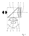
- the projector 1 shown in FIG. 1 comprises two projection lenses 2, the optical axes of which are each designated 3 and two each assigned to one of the projection lenses 2 Carriage 4.
- the carriage 4 can be moved approximately parallel to the optical axes 3 of the projection objectives 4 from a projection position into a change position.
- a control ensures that only one of the slides 4 is in its change position.
- an image template (slide) can be transported from a magazine 6 into a holder, which is arranged on the slide 4 and is designed as a slide stage 7, by means of a transport device 5.
- the carriage 4 is then moved into the projection position by a control.
- the lamp holder 8 is fixed in place in the projector 1 and consists of a concave mirror 9, a lamp 10 and a condenser lens 11 on the lamp side (FIG. 2).
- the optical axis of the lamp carrier 8, designated by 12, is essentially perpendicular to the optical axis 3 of the associated projection objective 2.
- the slide 4 When the slide 4 is in its projection position, the light emitted by the lamp holder along its optical axis 12 is reflected into the optical axis 3 of the projection lens 2 by a cold light mirror 13 arranged on the slide 4 at 45 ° to the optical axis 3 of the projection lens 2 .
- the infrared radiation emerges from the carriage 4 upwards essentially without reflection through the cold light mirror.
- the visible portion of the light emitted by the lamp holder 8 is reflected by the cold light mirror 13 in the optical axis 3 of the projection lens 2 and by a further condenser lens designed as converging lens 14 bundled into the entrance pupil of the projection objective 2.
- the slide stage 7 is mounted on the slide directly behind the converging lens 14.
- the slide 4 is then moved back into its change position by the control, where the slide is transported back into the magazine 6 by the transport device 5.
Landscapes
- Physics & Mathematics (AREA)
- General Physics & Mathematics (AREA)
- Projection Apparatus (AREA)
- Cold Cathode And The Manufacture (AREA)
- Non-Portable Lighting Devices Or Systems Thereof (AREA)
Description
- Die Erfindung betrifft einen Projektor mit wenigstens einem Projektionsobjektiv, einem dem Projektionsobjektiv zugeordneten, aus einer ersten Betriebsstellung bzw. einer Projektionsstellung in eine zweite Betriebsstellung bzw. eine Wechselstellung innerhalb des Projektors annähernd parallel zur optischen Achse des Projektionsobjektives verfahrbaren Schlitten, der zumindest eine Halterung bzw. eine Diabühne für eine zu projezierende durchleuchtbare Bildvorlage trägt, und wenigstens einem jeweils einem Projektionsobjektiv zugeordneten Kondensorsystem zur Beleuchtung der durchleuchtbaren Bildvorlage, wobei das Kondensorsystem wenigstens eine Lampe, einen Hohlspiegel, zumindest eine Kondensorlinse und eine Wärmeschutzvorrichtung für die Bildvorlage und die Halterung bzw. die Diabühne umfaßt.
- Solche Projektoren sind z. B. aus der DE-PS 35 17 376 bekannt und haben trotz der aufwendigen Mechanik den besonderen Vorzug, daß mit solchen Projektoren eine Überblendprojektion mit Bildvorlagen aus einem gemeinsamen Magazin möglich ist, d. h., daß die zu projezierenden Vorlagen nicht entsprechend der Projektionsfolge auf verschiedene Magazine verteilt werden müssen, sondern sogar in beliebiger Kombination und Reihenfolge einem herkömmlichen Magazin entnommen werden können. Die Zuordnung je eines Kondensorsystems zu einem Projektionsobjektiv erlaubt eine gute Lichtausbeute.
- Nachteilig bei solchen Projektoren ist jedoch, daß die Verfahrgeschwindigkeit des Schlittens zwischen seinen beiden Betriebsstellungen und damit die erzielbare Bildwechselfrequenz durch das hohe Gewicht der auf den Schlitten angebrachten Kondensorsysteme beschränkt ist. Zwar ließe sich die Verfahrgeschwindigkeit der Schlitten durch Verwendung leistungsfähigerer Antriebe erhöhen, jedoch würde dies durch die beim Beschleunigen und Verzögern des Schlittens auftretenden Reaktionskräfte zu Erschütterungen des Projektors und damit zu einem Zittern des gleichzeitig projezierten Bildes der anderen Bildvorlage führen.
- Weiterhin ist es bei solchen Projektoren nachteilig, daß der relativ hohe elektrische Strom zum Betrieb der üblicherweise verwendeten Niedervoltlampen auf den beweglichen Schlitten übertragen werden muß. Erfolgt dies durch eine fest angeschlossene Kabelschleppe, benötigt diese aufgrund der hohen Steifigkeit der erforderlichen großen Kabelquerschnitte relativ viel Platz. Bei Verwendung von Schleifkontakten, die in der Projektionsstellung des Schlittens einen elektrischen Kontakt ermöglichen, besteht stets die Gefahr von Funktionsstörungen. Bereits kleinste Übergangswiderstände, z. B. durch Staub, führen bei den großen zu übertragenden Strömen zu einem Leistungsverlust. Die dadurch bedingte Erhitzung der Schleifkontakte fördert deren Oberflächenkorrosion, wodurch der Übergangswiderstand und damit die Leistungsverluste weiter ansteigen.
- Schließlich ist bei den bekannten Projektoren noch nachteilig, daß das Beschleunigen und Abbremsen der heißen Lampe zu einem vorzeitigen unvorhergesehenen Ausfall der Lampe führen kann.
- Der Erfindung liegt daher die Aufgabe zugrunde, einen Projektor der eingangs beschreibenen Art hinsichtlich seiner Gebrauchseigenschaften und seiner Zuverlässigkeit zu verbessern.
- Diese Aufgabe wird erfindungsgemäße gelöst durch einen Projektor der eingangs erwähnten Art, der dadurch gekennzeichnet ist, daß das Kondensorsystem eine erste, im Projektor feststehende Baugruppe, die zumindest die Lampe, den Hohlspiegel und eine Kondensorlinse enthält, und eine zweite, auf dem Schlitten angeordnete, wenigstens die Halterung bzw. die Diabühne enthaltende Baugruppe umfaßt.
- Der erfindungsgemäße Projektor weist den großen Vorteil auf, daß die die zuvor erwähnten Nachteile im wesentlichen bestimmenden Teile des Kondensorsystems außerhalb des Schlittens in einer feststehenden Baugruppe angeordnet sind. Dies ermöglicht eine erheblich höhere Verfahrgeschwindigkeit des Schlittens, da die lampenseitige Kondensorlinse, die im wesentlichen die Masse des Kondensorsystems bestimmt, nunmehr im Projektor feststeht. Durch die ortsfeste Anordnung der Lampe im Projektor kann diese direkt fest angeschlossen werden, wodurch die Nachteile von Kabelschleppen oder Schleifkontakten entfallen. Ferner ist die Lampe durch die ortsfeste Anordnung im Projektor vor mechanischen Beanspruchungen, die zu einem vorzeitigen Ausfall führen können, geschützt.
- Für eine gute Lichtausbeute ist es dabei zweckmäßig, wenn die optische Achse der ersten Baugruppe bzw. des Lampenträgers in einem Winkel zur Bewegungsrichtung des Schlittens angeordnet ist und wenn der Schlitten ferner einen Spiegel umfaßt, der unter dem halben Winkel zwischen optischer Achse des Lampenträgers und der Bewegungsrichtung zur Bewegungsrichtung des Schlittens auf diesem angebracht ist.
- Dabei erlaubt der auf dem Schlitten angeordnete Spiegel, daß in der Projektionsstellung des Schlittens das von dem Lampenträger ausgesandte Lichtbündel in die optische Achse des Projektionsobjektives fällt.
- Für einen besonders kompakten Aufbau eines solchen Projektors ist es besonders zweckmäßig, wenn die optische Achse des Lampenträgers rechtwinklig zur Bewegungsrichtung des Schlittens angeordnet ist.
- In einer bevorzugten Ausführungsform der Erfindung ist der Spiegel ein Kaltlichtspiegel. Dadurch wird die Ablenkung des Infrarotanteils des von dem Lampenträger ausgesandten Lichtbündels in die optische Achse und damit die thermische Belastung der Bildvorlage und des Projektionsobjektives vermindert.
- Dabei ist es besonders zweckmäßig, wenn der Kaltlichtspiegel die Wärmeschutzvorrichtung für die Bildvorlage ist. Dadurch kann die Verwendung eines herkömmlichen Wärmeschutzfilters für die Bildvorlage entfallen.
- In einer weiteren besonders vorteilhaften Ausführungsform eines erfindungsgemäßen Projektors ist dieser dadurch gekennzeichnet, daß die auf dem Schlitten angeordnete Baugruppe ferner eine weitere Kondensorlinse umfaßt. Diese ermöglicht in der Projektionsstellung des Schlittens die Abbildung der Lampenwendel in die Eintrittspupille des Projektionsobjektives und erhöht so die Lichtausbeute wesentlich.
- Die Erfindung soll im folgenden anhand eines in der Zeichnung dargestellten Ausführungsbeispiels näher erläutert werden. Es zeigen:
- Figur 1 -
- eine Draufsicht auf einen geöffneten erfindungsgemäßen Projektor, bei dem der Lampenträger unterhalb des Schlittens angeordnet ist, und
- Figur 2 -
- eine schematische Seitenansicht eines Kondensorsystems eines erfindungsgemäßen Projektors.
- Der in Figur 1 dargestellte Projektor 1 umfaßt zwei Projektionsobjektive 2, deren optische Achsen jeweils mit 3 bezeichnet sind und zwei jeweils einem der Projektionsobjektive 2 zugeordnete Schlitten 4. Die Schlitten 4 sind annähernd parallel zu den optischen Achsen 3 der Projektionsobjektive 4 aus einer Projektionsstellung in eine Wechselstellung verfahrbar.
- Über eine nicht dargestellte Steuerung ist gewährleistet, daß sich jeweils nur einer der Schlitten 4 in seiner Wechselstellung befindet. In der Wechselstellung kann durch eine Transporteinrichtung 5 eine Bildvorlage (Dia) aus einem Magazin 6 in eine auf dem Schlitten 4 angeordnete, als Diabühne 7 ausgebildete Halterung transportiert werden.
- Durch eine Steuerung wird anschließend der Schlitten 4 in die Projektionsstellung verfahren.
- Sobald sich der Schlitten 4 in seiner Projektionsstellung befindet, nimmt er eine Position über einem Lampenträger 8 ein.
- Der Lampenträger 8 ist in dem Projektor 1 ortsfest montiert und besteht aus einem Hohlspiegel 9, einer Lampe 10 und einer lampenseitigen Kondensorlinse 11 (Figur 2).
- Die mit 12 bezeichnete optische Achse des Lampenträgers 8 steht dabei im wesentlichen senkrecht auf der optischen Achse 3 des zugeordneten Projektionsobjektivs 2.
- Wenn sich der Schlitten 4 in seiner Projektionsstellung befindet, wird das von dem Lampenträger entlang seiner optischen Achse 12 ausgesandte Licht durch einen auf dem Schlitten 4 unter 45° zur optischen Achse 3 des Projektionsobjektivs 2 angeordneten Kaltlichtspiegels 13 in die optische Achse 3 des Projektionsobjektivs 2 gespiegelt. Dabei tritt die Infrarotstrahlung im wesentlichen ungespiegelt durch den Kaltlichtspiegel nach oben aus dem Schlitten 4 aus.
- Der sichtbare Anteil des von dem Lampenträgers 8 ausgesandten Lichtes wird durch den Kaltlichtspiegel 13 in die optische Achse 3 des Projektionsobjektives 2 gespiegelt und durch eine als Sammellinse 14 ausgebildete weitere Kondensorlinse in die Eintrittspupille des Projektionsobjektivs 2 gebündelt. Direkt hinter der Sammellinse 14 ist die Diabühne 7 auf dem Schlitten angebracht.
- Zum Wechseln des Dias wird der Schlitten 4 dann durch die Steuerung wieder in seine Wechselstellung verfahren, wo das Dia durch die Transporteinrichtung 5 in das Magazin 6 zurücktransportiert wird.
Claims (6)
- Projektor (1) mit wenigstens einem Projektionsobjektiv (2), einem dem Projektionsobjektiv (2) zugeordneten, aus einer ersten Betriebsstellung bzw. einer Projektionsstellung in eine zweite Betriebsstellung bzw. eine Dia-Wechselstellung innerhalb des Projektors (1) annähernd parallel zur optischen Achse (3) des Projektionsobjektives (2) verfahrbaren Schlitten (4), der zumindest eine Halterung bzw. eine Diabühne (7) für eine zu projezierende durchleuchtbare Bildvorlage trägt, und wenigstens einem jeweils einem Projektionsobjektiv (2) zugeordneten Kondensorsystem zur Beleuchtung der durchleuchtbaren Bildvorlage, wobei das Kondensorsystem wenigstens eine Lampe (10), einen Hohlspiegel (9), zumindest eine Kondensorlinse (11, 14) und eine Wärmeschutzvorrichtung für die Bildvorlage und die Halterung bzw. die Diabühne (7) umfaßt, dadurch gekennzeichnet, daß das Kondensorsystem eine erste, im Projektor feststehende Baugruppe (8), die zumindest die Lampe (10), den Hohlspiegel (9) und eine Kondensorlinse (11) enthält, und eine zweite, auf dem Schlitten (4) angeordnete, wenigstens die Halterung bzw. die Diabühne (7) enthaltende Baugruppe umfaßt.
- Projektor nach Anspruch 1, dadurch gekennzeichnet, daß die optische Achse (12) der ersten Baugruppe (8) in einem Winkel zur Bewegungsrichtung des Schlittens (4) angeordnet ist und daß der Schlitten (4) ferner einen Spiegel (13) umfaßt, der unter dem halben Winkel zwischen optischer Achse (12) der ersten Baugruppe (8) und der Bewegungsrichtung des Schlittens (4) auf diesem angebracht ist.
- Projektor nach Anspruch 2, dadurch gekennzeichnet, daß die optische Achse (12) der ersten Baugruppe (8) rechtwinklig zur Bewegungsrichtung des Schlittens (4) angeordnet ist.
- Projektor nach Anspruch 2 oder 3, dadurch gekennzeichnet, daß der Spiegel (13) ein Kaltlichtspiegel ist.
- Projektor nach Anspruch 4, dadurch gekennzeichnet, daß der Kaltlichtspiegel (13) die Wärmeschutzvorrichtung für die Bildvorlage ist.
- Projektor nach einem der vorhergehenden Ansprüche, dadurch gekennzeichnet, daß die zweite auf dem Schlitten (4) angeordnete Baugruppe ferner eine weitere Kondensorlinse (14) umfaßt.
Applications Claiming Priority (3)
| Application Number | Priority Date | Filing Date | Title |
|---|---|---|---|
| DE4314457A DE4314457C1 (de) | 1993-05-03 | 1993-05-03 | Projektor |
| DE4314457 | 1993-05-03 | ||
| PCT/DE1994/000510 WO1994025897A1 (de) | 1993-05-03 | 1994-05-03 | Projektor |
Publications (2)
| Publication Number | Publication Date |
|---|---|
| EP0648346A1 EP0648346A1 (de) | 1995-04-19 |
| EP0648346B1 true EP0648346B1 (de) | 1997-07-16 |
Family
ID=6486956
Family Applications (1)
| Application Number | Title | Priority Date | Filing Date |
|---|---|---|---|
| EP94914320A Expired - Lifetime EP0648346B1 (de) | 1993-05-03 | 1994-05-03 | Projektor |
Country Status (5)
| Country | Link |
|---|---|
| EP (1) | EP0648346B1 (de) |
| CN (1) | CN1053279C (de) |
| AT (1) | ATE155590T1 (de) |
| DE (2) | DE4314457C1 (de) |
| WO (1) | WO1994025897A1 (de) |
Family Cites Families (7)
| Publication number | Priority date | Publication date | Assignee | Title |
|---|---|---|---|---|
| DE2023035A1 (de) * | 1970-05-12 | 1971-12-02 | Engert H | Stehbildprojektor,insbesondere UEberblendprojektor |
| US4094599A (en) * | 1977-08-22 | 1978-06-13 | Frey Gerald J | Flexible magazine slide projector with movable lens |
| DE2743757A1 (de) * | 1977-09-29 | 1979-04-12 | Agfa Gevaert Ag | Diaprojektor |
| DE2930958C2 (de) * | 1979-07-31 | 1981-03-19 | Rollei-Werke Franke & Heidecke Gmbh & Co Kg, 3300 Braunschweig | Überblend-Stehbildwerfer |
| DE3410024A1 (de) * | 1984-03-19 | 1985-09-19 | Demolux Gmbh & Co Kg, 6070 Langen | Kombinationsprojektor |
| DE3517376C1 (de) * | 1985-05-14 | 1986-04-24 | Rollei Fototechnic GmbH, 3300 Braunschweig | Überblendprojektor |
| DE3532723A1 (de) * | 1985-09-13 | 1987-03-19 | Hund Helmut Gmbh | Beleuchtungsanordnung in projektoren |
-
1993
- 1993-05-03 DE DE4314457A patent/DE4314457C1/de not_active Expired - Fee Related
-
1994
- 1994-05-03 AT AT94914320T patent/ATE155590T1/de not_active IP Right Cessation
- 1994-05-03 CN CN94190262A patent/CN1053279C/zh not_active Expired - Fee Related
- 1994-05-03 WO PCT/DE1994/000510 patent/WO1994025897A1/de not_active Ceased
- 1994-05-03 DE DE59403374T patent/DE59403374D1/de not_active Expired - Fee Related
- 1994-05-03 EP EP94914320A patent/EP0648346B1/de not_active Expired - Lifetime
Also Published As
| Publication number | Publication date |
|---|---|
| CN1053279C (zh) | 2000-06-07 |
| DE4314457C1 (de) | 1994-09-08 |
| WO1994025897A1 (de) | 1994-11-10 |
| ATE155590T1 (de) | 1997-08-15 |
| DE59403374D1 (de) | 1997-08-21 |
| EP0648346A1 (de) | 1995-04-19 |
| CN1109261A (zh) | 1995-09-27 |
Similar Documents
| Publication | Publication Date | Title |
|---|---|---|
| DE4036199A1 (de) | Fahrzeugbeleuchtungsanordnung, insbesondere fuer motorfahrzeuge | |
| DE19526512A1 (de) | Beleuchtungsvorrichtung für Fahrzeuge | |
| DE4304530A1 (en) | Lighting device e.g. for objects recorded by video camera - has controller for intensity operation by pivoting and displacing lamp, condenser system and/or optical system | |
| WO1993001068A1 (de) | Scheinwerfersystem für fahrzeuge | |
| DE19822142A1 (de) | Verfahren und Vorrichtung zum Erzeugen eines vor einem Kraftfahrzeug auf die Fahrbahn auftreffenden Lichtbündels | |
| DE2211197C3 (de) | Projektions-Kopiergerät mit fortschreitend streifenweiser Abtastung der ruhenden Vorlage | |
| DE102019131155A1 (de) | Lidar-integrierte beleuchtungsvorrichtung für ein fahrzeug | |
| DE2460074C3 (de) | Linsenvorrichtung in Projektions-Kopiergeräten mit veränderlicher Vergrößerung | |
| DE60034085T2 (de) | Kraftfahrzeug-Scheinwerfer zur Erzeugung von zwei verschiedenen Lichtstrahlen mit einer einzigen Lichtquelle | |
| WO2002068861A1 (de) | Beleuchtungs- und signalvorrichtungen für fahr- oder flugzeuge | |
| DE1934090A1 (de) | Automatische Abblendvorrichtung fuer Scheinwerfer | |
| DE2626864C2 (de) | Mikroskop-Universalkondensor | |
| EP0648346A1 (de) | Projektor. | |
| DE2555398C2 (de) | Optische Abtastvorrichtung | |
| DE69207787T2 (de) | Augenbeobachtungsgerät | |
| DE3438322A1 (de) | Verfahren und einrichtung zur uebertragung von signaldaten | |
| DE1252931B (de) | Einrichtung zum Scharfeinstellen eines Bildwerfers | |
| DE4315630A1 (de) | Varioabbildungssystem mit endlicher Übertragungslänge | |
| DE879605C (de) | Optisches Instrument mit gekuppeltem Objektiv- und Kondensor-Wechsler | |
| DE974125C (de) | Projektionsapparate, insbesondere Mikroablesegeraete | |
| DE60225551T2 (de) | Leuchtengehäuse | |
| DD148820B1 (de) | Optisches entzerrungsgeraet | |
| EP0648347B1 (de) | Projektor | |
| DE909293C (de) | Vorrichtung an Reproduktionsapparaten | |
| DE3318768A1 (de) | Justiervorrichtung und ablenkkopf fuer einen laserstrahl einer laser-beschriftungsanlage |
Legal Events
| Date | Code | Title | Description |
|---|---|---|---|
| PUAI | Public reference made under article 153(3) epc to a published international application that has entered the european phase |
Free format text: ORIGINAL CODE: 0009012 |
|
| 17P | Request for examination filed |
Effective date: 19950104 |
|
| AK | Designated contracting states |
Kind code of ref document: A1 Designated state(s): AT CH DE IT LI |
|
| GRAG | Despatch of communication of intention to grant |
Free format text: ORIGINAL CODE: EPIDOS AGRA |
|
| GRAH | Despatch of communication of intention to grant a patent |
Free format text: ORIGINAL CODE: EPIDOS IGRA |
|
| 17Q | First examination report despatched |
Effective date: 19961021 |
|
| GRAH | Despatch of communication of intention to grant a patent |
Free format text: ORIGINAL CODE: EPIDOS IGRA |
|
| RAP1 | Party data changed (applicant data changed or rights of an application transferred) |
Owner name: ROLLEI FOTOTECHNIC GMBH |
|
| GRAA | (expected) grant |
Free format text: ORIGINAL CODE: 0009210 |
|
| AK | Designated contracting states |
Kind code of ref document: B1 Designated state(s): AT CH DE IT LI |
|
| REF | Corresponds to: |
Ref document number: 155590 Country of ref document: AT Date of ref document: 19970815 Kind code of ref document: T |
|
| REG | Reference to a national code |
Ref country code: CH Ref legal event code: NV Representative=s name: ANDRE BRAUN PATENTANWALT VSP Ref country code: CH Ref legal event code: EP |
|
| REF | Corresponds to: |
Ref document number: 59403374 Country of ref document: DE Date of ref document: 19970821 |
|
| ITF | It: translation for a ep patent filed | ||
| PLBE | No opposition filed within time limit |
Free format text: ORIGINAL CODE: 0009261 |
|
| STAA | Information on the status of an ep patent application or granted ep patent |
Free format text: STATUS: NO OPPOSITION FILED WITHIN TIME LIMIT |
|
| 26N | No opposition filed | ||
| PGFP | Annual fee paid to national office [announced via postgrant information from national office to epo] |
Ref country code: AT Payment date: 20030512 Year of fee payment: 10 |
|
| PGFP | Annual fee paid to national office [announced via postgrant information from national office to epo] |
Ref country code: DE Payment date: 20030514 Year of fee payment: 10 |
|
| PGFP | Annual fee paid to national office [announced via postgrant information from national office to epo] |
Ref country code: CH Payment date: 20030528 Year of fee payment: 10 |
|
| PG25 | Lapsed in a contracting state [announced via postgrant information from national office to epo] |
Ref country code: AT Free format text: LAPSE BECAUSE OF NON-PAYMENT OF DUE FEES Effective date: 20040503 |
|
| PG25 | Lapsed in a contracting state [announced via postgrant information from national office to epo] |
Ref country code: LI Free format text: LAPSE BECAUSE OF NON-PAYMENT OF DUE FEES Effective date: 20040531 Ref country code: CH Free format text: LAPSE BECAUSE OF NON-PAYMENT OF DUE FEES Effective date: 20040531 |
|
| PG25 | Lapsed in a contracting state [announced via postgrant information from national office to epo] |
Ref country code: DE Free format text: LAPSE BECAUSE OF NON-PAYMENT OF DUE FEES Effective date: 20041201 |
|
| REG | Reference to a national code |
Ref country code: CH Ref legal event code: PL |
|
| PG25 | Lapsed in a contracting state [announced via postgrant information from national office to epo] |
Ref country code: IT Free format text: LAPSE BECAUSE OF NON-PAYMENT OF DUE FEES Effective date: 20050503 |