EP0646778B1 - Apparatus for measuring temperature using optical fiber and method therefor - Google Patents
Apparatus for measuring temperature using optical fiber and method therefor Download PDFInfo
- Publication number
- EP0646778B1 EP0646778B1 EP94115679A EP94115679A EP0646778B1 EP 0646778 B1 EP0646778 B1 EP 0646778B1 EP 94115679 A EP94115679 A EP 94115679A EP 94115679 A EP94115679 A EP 94115679A EP 0646778 B1 EP0646778 B1 EP 0646778B1
- Authority
- EP
- European Patent Office
- Prior art keywords
- optical fiber
- gas
- nozzle
- metal
- temperature
- Prior art date
- Legal status (The legal status is an assumption and is not a legal conclusion. Google has not performed a legal analysis and makes no representation as to the accuracy of the status listed.)
- Expired - Lifetime
Links
Images






Classifications
-
- G—PHYSICS
- G01—MEASURING; TESTING
- G01J—MEASUREMENT OF INTENSITY, VELOCITY, SPECTRAL CONTENT, POLARISATION, PHASE OR PULSE CHARACTERISTICS OF INFRARED, VISIBLE OR ULTRAVIOLET LIGHT; COLORIMETRY; RADIATION PYROMETRY
- G01J5/00—Radiation pyrometry, e.g. infrared or optical thermometry
- G01J5/48—Thermography; Techniques using wholly visual means
-
- G—PHYSICS
- G01—MEASURING; TESTING
- G01J—MEASUREMENT OF INTENSITY, VELOCITY, SPECTRAL CONTENT, POLARISATION, PHASE OR PULSE CHARACTERISTICS OF INFRARED, VISIBLE OR ULTRAVIOLET LIGHT; COLORIMETRY; RADIATION PYROMETRY
- G01J5/00—Radiation pyrometry, e.g. infrared or optical thermometry
- G01J5/0037—Radiation pyrometry, e.g. infrared or optical thermometry for sensing the heat emitted by liquids
- G01J5/004—Radiation pyrometry, e.g. infrared or optical thermometry for sensing the heat emitted by liquids by molten metals
-
- G—PHYSICS
- G01—MEASURING; TESTING
- G01J—MEASUREMENT OF INTENSITY, VELOCITY, SPECTRAL CONTENT, POLARISATION, PHASE OR PULSE CHARACTERISTICS OF INFRARED, VISIBLE OR ULTRAVIOLET LIGHT; COLORIMETRY; RADIATION PYROMETRY
- G01J5/00—Radiation pyrometry, e.g. infrared or optical thermometry
- G01J5/02—Constructional details
-
- G—PHYSICS
- G01—MEASURING; TESTING
- G01J—MEASUREMENT OF INTENSITY, VELOCITY, SPECTRAL CONTENT, POLARISATION, PHASE OR PULSE CHARACTERISTICS OF INFRARED, VISIBLE OR ULTRAVIOLET LIGHT; COLORIMETRY; RADIATION PYROMETRY
- G01J5/00—Radiation pyrometry, e.g. infrared or optical thermometry
- G01J5/02—Constructional details
- G01J5/0205—Mechanical elements; Supports for optical elements
-
- G—PHYSICS
- G01—MEASURING; TESTING
- G01J—MEASUREMENT OF INTENSITY, VELOCITY, SPECTRAL CONTENT, POLARISATION, PHASE OR PULSE CHARACTERISTICS OF INFRARED, VISIBLE OR ULTRAVIOLET LIGHT; COLORIMETRY; RADIATION PYROMETRY
- G01J5/00—Radiation pyrometry, e.g. infrared or optical thermometry
- G01J5/02—Constructional details
- G01J5/04—Casings
- G01J5/041—Mountings in enclosures or in a particular environment
-
- G—PHYSICS
- G01—MEASURING; TESTING
- G01J—MEASUREMENT OF INTENSITY, VELOCITY, SPECTRAL CONTENT, POLARISATION, PHASE OR PULSE CHARACTERISTICS OF INFRARED, VISIBLE OR ULTRAVIOLET LIGHT; COLORIMETRY; RADIATION PYROMETRY
- G01J5/00—Radiation pyrometry, e.g. infrared or optical thermometry
- G01J5/02—Constructional details
- G01J5/04—Casings
- G01J5/041—Mountings in enclosures or in a particular environment
- G01J5/045—Sealings; Vacuum enclosures; Encapsulated packages; Wafer bonding structures; Getter arrangements
-
- G—PHYSICS
- G01—MEASURING; TESTING
- G01J—MEASUREMENT OF INTENSITY, VELOCITY, SPECTRAL CONTENT, POLARISATION, PHASE OR PULSE CHARACTERISTICS OF INFRARED, VISIBLE OR ULTRAVIOLET LIGHT; COLORIMETRY; RADIATION PYROMETRY
- G01J5/00—Radiation pyrometry, e.g. infrared or optical thermometry
- G01J5/02—Constructional details
- G01J5/04—Casings
- G01J5/046—Materials; Selection of thermal materials
-
- G—PHYSICS
- G01—MEASURING; TESTING
- G01J—MEASUREMENT OF INTENSITY, VELOCITY, SPECTRAL CONTENT, POLARISATION, PHASE OR PULSE CHARACTERISTICS OF INFRARED, VISIBLE OR ULTRAVIOLET LIGHT; COLORIMETRY; RADIATION PYROMETRY
- G01J5/00—Radiation pyrometry, e.g. infrared or optical thermometry
- G01J5/02—Constructional details
- G01J5/05—Means for preventing contamination of the components of the optical system; Means for preventing obstruction of the radiation path
-
- G—PHYSICS
- G01—MEASURING; TESTING
- G01J—MEASUREMENT OF INTENSITY, VELOCITY, SPECTRAL CONTENT, POLARISATION, PHASE OR PULSE CHARACTERISTICS OF INFRARED, VISIBLE OR ULTRAVIOLET LIGHT; COLORIMETRY; RADIATION PYROMETRY
- G01J5/00—Radiation pyrometry, e.g. infrared or optical thermometry
- G01J5/02—Constructional details
- G01J5/05—Means for preventing contamination of the components of the optical system; Means for preventing obstruction of the radiation path
- G01J5/051—Means for preventing contamination of the components of the optical system; Means for preventing obstruction of the radiation path using a gas purge
-
- G—PHYSICS
- G01—MEASURING; TESTING
- G01J—MEASUREMENT OF INTENSITY, VELOCITY, SPECTRAL CONTENT, POLARISATION, PHASE OR PULSE CHARACTERISTICS OF INFRARED, VISIBLE OR ULTRAVIOLET LIGHT; COLORIMETRY; RADIATION PYROMETRY
- G01J5/00—Radiation pyrometry, e.g. infrared or optical thermometry
- G01J5/02—Constructional details
- G01J5/08—Optical arrangements
- G01J5/0818—Waveguides
- G01J5/0821—Optical fibres
-
- G—PHYSICS
- G01—MEASURING; TESTING
- G01K—MEASURING TEMPERATURE; MEASURING QUANTITY OF HEAT; THERMALLY-SENSITIVE ELEMENTS NOT OTHERWISE PROVIDED FOR
- G01K1/00—Details of thermometers not specially adapted for particular types of thermometer
- G01K1/08—Protective devices, e.g. casings
- G01K1/10—Protective devices, e.g. casings for preventing chemical attack
- G01K1/105—Protective devices, e.g. casings for preventing chemical attack for siderurgical use
-
- G—PHYSICS
- G01—MEASURING; TESTING
- G01J—MEASUREMENT OF INTENSITY, VELOCITY, SPECTRAL CONTENT, POLARISATION, PHASE OR PULSE CHARACTERISTICS OF INFRARED, VISIBLE OR ULTRAVIOLET LIGHT; COLORIMETRY; RADIATION PYROMETRY
- G01J5/00—Radiation pyrometry, e.g. infrared or optical thermometry
- G01J5/60—Radiation pyrometry, e.g. infrared or optical thermometry using determination of colour temperature
Definitions
- the present invention relates to an apparatus for measuring a temperature of a high temperature liquid using an optical fiber and a method therefor and in particular to the apparatus and the method which allow a continuous measurement.
- a prior art method for measuring a temperature of molten metal in a furnace such as a converter processing a decarburization of molten iron, one of the steel smelting furnaces, adopts a sublance method or a manually operating thermocouple measurement method.
- a thermometer element attached at a tip of a movable lance is inserted through a raw material charge hole on the furnace or other hole to perform the temperature measurement. Accordingly, the sublance method has disadvantages given below.
- thermometer element a size of apparatus for measuring a temperature is enlarged in proportion to a size of the furnace.
- replacement of a thermometer element is forcedly required in every measuring cycle because the thermometer element is of one time disposable type, and further the replacement of the thermometer element is also required.
- intermittent measurement of the temperature forcedly carried out during operation because the consumption type thermocouple is forcedly replaced in every measurement cycle.
- frequent measurement is not allowed in view of an economic reason because of the disposition of such a thermometer element every measurement cycle.
- an actual observed temperature at the end of the process does not always agree with a target temperature, which often causes problems of generation of energy loss, increase of production cost, and degradation of productivity.
- JP-A-91529/1986 discloses a method for measuring a temperature in a furnace using an optical fiber.
- the optical fiber is fixed at the tip of a nozzle so that the temperature measurement is carried out through a gas layer which is ejected from the tip of the nozzle. For this reason, this measuring method raises a serious problem on accuracy of the measured result.
- the tip of the optical fiber is exposed to an elevated temperature for a long period, which raises a problem of change of characteristics with passing time.
- JP-A-203716/1988 discloses another method of continuous measurement of a molten steel.
- the method relates to a control method of making the molten steel by blowing in which the temperature of molten steel is continuously measured so as to agree during and at the end of blowing stage with the target value, and in which the composition at the end point is estimated from the change rate of the temperature increase.
- the patent specification describes "a method for measuring a temperature of a molten steel is applicable to using a radiation thermometer connecting an optical fiber, which thermometer immerses the optical fiber into the molten steel in a reaction vessel such as a converter through its bottom wall, side wall, or top cover". Nevertheless, in the specification no concrete description is given and no technological content is provided.
- the inventors proposed an apparatus for measuring a temperature in the preceding Japanese Patent Application No. 78736/92 (JP-A-24896/93).
- the patent application provided the apparatus by immersing a tip of an optical fiber covered with a metallic tube into a molten steel as a thermometer element, by using the principle that a black body radiation condition is established at the tip of the optical fiber, and by connecting the other end of the optical fiber to a radiation thermometer.
- the patent application provided an apparatus for measuring a temperature in which an optical fiber feed means is installed to send out and also to retract to wind the optical fiber covered with a metallic tube and in which the tip of the optical fiber covered with a metallic tube is immersed into the molten steel for a short period only during the time for measuring the temperature thereof and is taken out from the molten steel immediately after completing the temperature measurement and in which the tip once used as the thermometer element is cut off to discard, and a new tip is fed at next measuring cycle.
- JP-A-24896/93 The apparatus for measuring a temperature disclosed in Japanese Patent Application No. 78736/92 (JP-A-24896/93) is, however, a mere intermittent measuring apparatus, and the apparatus needs to cut off the used tip in every measurement cycle. As the result, there is a problem in that that type of apparatus fails to perform a continuous measurement for a long period.
- An object of the present invention is to provide an apparatus for measuring a temperature of a high temperature liquid using an optical fiber and a method therefor which allow a continuous and long period measurement with a quick response and an accurate measurement.
- the present invention provides an apparatus for measuring a high temperature liquid contained in a furnace, which comprises the features in accordance with claim 1 below.
- an optical fiber covered with a metallic tube is used.
- a nozzle for measuring a temperature of a high temperature liquid is installed on a wall of a furnace which contains the high temperature liquid. An end of the nozzle contacts the high temperature liquid while the metal-covered optical fiber is inserted from another end of the nozzle.
- Gas is supplied into the nozzle by gas supply means for supplying gas to prevent the nozzle from clogging. The gas is blown into the liquid in the furnace, passing through a spacious gap between the nozzle and the metal-covered optical fiber.
- An end of the metal-covered optical fiber is sent out to the inside of the liquid by optical fiber feed means for sending out the metal-covered optical fiber.
- a spectral light enters from an end of the metal-covered optical fiber. Another end of the metal-covered optical fiber is connected to a radiation thermometer and a temperature of the high temperature liquid is determined from the spectral light transferred into an inside of the metal-covered optical fiber.
- the optical fiber feed means comprises a drum in which the metal-covered optical fiber is coiled in advance, a roller for sending out the metal-covered optical fiber, a motor for driving the roller, feed speed detecting means for detecting a feed speed of sending out the metal-covered optical fiber and feed speed control means for controlling the feed speed.
- the motor is drived, the roller works and then, the metal-covered optical fiber is sent out.
- the feed speed is detected by a detector which is the detecting means.
- the feed speed is controlled by the feed speed controller based on a feed speed signal outputted from the detector.
- the metal-covered optical fiber is inserted into the nozzle for temperature measurement and gas is blown into an inside of the high temperature liquid, passing through a spacious gap between the nozzle and the metal-covered optical fiber. Therefore, a ratio of an inside diameter of the nozzle to an outside of the metal-covered optical fiber ranges preferably from 1.5 to 3.5.
- the nozzle for temperature measurement can be one selected from the group consisting of a nozzle made of brick or ceramics, a nozzle made of a single metalic tube and a nozzle made of a single metallic tube lined with ceramics inside a surface thereof.
- the temperature measurement nozzle can be of a double-tube structure comprising an inner tube and an outer tube. The metal-covered optical fiber is inserted into the inner tube of the nozzle and gas is supplied through a spacious gap between the inner tube and the outer tube by gas supply means to prevent the nozzle from clogging.
- the gas supply means comprises gas selection means for selecting a kind of gas and gas velocity control means for controlling a velocity of gas. Further, the gas supply means has pressure detecting means.
- the gas selection means selects a kind of gas dependent on a degree of difficulty in sending out the metal-covered optical fiber by the optical fiber feed means.
- the gas velocity control means controls the gas which is blown out to have a linear velocity within a range of 50 to 500 Nm/sec at a tip of the nozzle where the nozzle contacts the high temperature liquid.
- the gas used for preventing the nozzle from clogging can be any one selected from the group consisting of an inert gas, a mixed gas of an inert gas and an oxidating gas and an oxidating gas.
- the pressure detecting means detects a pressure of the gas which is supplied into the temperature measurement nozzle to prevent the nozzle from clogging.
- the gas selection means can also select a kind of gas which is supplied into the nozzle in response to a pressure signal outputted from the pressure detecting means and a feed speed signal outputted from the feed speed detecting means.
- Gas is supplied into the nozzle for temperature measurement by the gas supply means to prevent the nozzle from clogging.
- mushroom is formed at a tip end of the nozzle if the flow speed is too large.
- the mushroom is a spongy lump which a molten metal is partially solidified to form.
- the metal-covered optical fiber fails to be inserted. It can be a way of solving the formation of the mushroom to melt the mushroom by oxygen blowing and to send out the metal-covered optical fiber. In this way of blowing the oxygen, however, the melt-loss of the nozzle is a problem not to neglect. And furthermore, reaction of metal oxidation takes place at the vicinity of an outlet of the nozzle, and the accuracy of the measurment is degraded.
- the mushroom is not formed when relation among temperature of the gas, kind of the gas, flow rate of the gas and composition of the molten metal satisfies an equation (1) given below. Therefore, the temperature measurement can be continuously performed by controlling the flow rate of the gas to be within the scope of the equation (1) while the formation of the mushroom is being prevented. Thanks to this way of doing, the oxygen blowing is not needed and therefore, the melt-loss and the degradation of the accuracy of the measurement are also prevented.
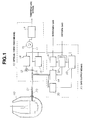
- Fig. 1 illustrates a block diagram showing an apparatus for measuring a temperature using an optical fiber of Example-1 of the present invention.
- the reference numeral 10 denotes optical fiber feed means which comprises an optical fiber 11 covered with metallic tube, a motor 12, a roller 13, feed control means 14, feed speed detecting means 15, an optical fiber drum 16, and a radiation thermometer 17.
- the reference numeral 20 denotes a nozzle used for temperature measurement to insert the metal-covered optical fiber 11 into a furnace, and the nozzle is also called a temperature measuring tuyere.
- the reference numeral 21 denotes an optical fiber guide which connects with the nozzle 20, through which the metal-covered optical fiber 11 is passed and gas for preventing the nozzle from clogging up is supplied.
- the reference numeral 30 denotes gas supply means for supplying gas which prevents the nozzle from clogging, which comprises two gas pressure/flow rate regulators 31 and 32, a supply gas controller 33, a supply gas generator 34, and a gas pressure detector 35.
- the reference numeral 40 denotes a furnace such as a converter or an electric furnace. The example shown in the figure illustrates the nozzle 20 used in measuring a temperature mounted at a side wall of the furnace 40. Nevertheless, the nozzle 20 can be mounted at a bottom of the furnace 40.
- the apparatus for measuring a temperature of the present example using an optical fiber enables to carry out a continuous temperature measurement of a high temperature liquid, for example, molten metal in a furnace, by directly immersing a tip of the metal-covered optical fiber 11 into a molten metal or slag in the furnace together with a gas for preventing the nozzle clogging (nitrogen gas, for example), and by continuously feeding a fresh portion of the metal-covered optical fiber to supply a new tip of the metal-covered optical fiber 11 to make up the melted out tip of the metal-covered optical fiber.
- a gas for preventing the nozzle clogging nitrogen gas, for example
- the reason why the optical fiber is covered with a metallic tube is to secure a strength for enduring a pressure of gas for preventing the nozzle from clogging due to the pressure imposed on the optical fiber during a feeding period of the optical fiber into the furnace using the optical fiber feed means 10 and also to protect the optical fiber inside of the metallic tube.
- the metallic tube covering the optical fiber is, for example, a stainless steel tube. Since a melting point of stainless steel ranges about from 1400 to 1430°C, the metallic tube does not melt immediately after immersed into a high temperature molten steel and protects the optical fiber for several seconds. Also since Example-1 uses a quartz glass having a softening point of 1600°C or more as the optical fiber, the optical fiber can maintain its original shape for a short time. In the present example the metal-covered optical fiber 11 having 1.2 mm in outside diameter was employed.
- the temperature measurement nozzle 20 can be made of brick or ceramics, a single metallic tube, or a single metallic tube with ceramics lined inside thereof.
- Another example of the nozzle has a double-tube structure in which the temperature measuring tube made of a single metallic tube or a single metallic nozzle with ceramics lined inside thereof is surrounded by a concentric metallic tube, and a spacious gap formed between the outside diameter of the inner nozzle and the inside diameter of the outer metallic tube is connected to the gas supply means 30 which supplies gas to prevent the nozzle's clogging.
- the temperature measurement nozzle 20 contacts the high temperature liquid at an end thereof, and connects to an optical fiber guide 21 on another end in air-tight sealing.
- the metal-covered optical fiber 11 is inserted through the nozzle 20 from the side of the optical fiber guide 21 and is immersed into the high temperature liquid. There secured a spacious gap between the inside diameter of the nozzle 20 and the outside diameter of the metal-covered optical fiber 11, and the preventive gas against the nozzle's clogging is supplied into the spacious gap via the optical fiber guide 21.
- Fig. 2 illustrates an example of the nozzle 20 for temperature measurement, which comprises a single metallic tube lined with ceramics inside surface thereof.
- the nozzle 20 is structured with a stainless tube 20a having a ceramic tube 20b inside the stainless tube.
- the example uses SUS 304 as the stainless steel tube 20a and silicon nitride (Si 3 N 4 ) as the ceramic tube 20b.
- the ceramic is not necessarily limited to silicon nitride, and boron nitride (BN), zirconium oxide (ZrO 2 ) and other ceramics can be applied.
- a metallic tube lined with ceramics inside thereof can be also applied.
- the stainless steel tube 20a is accompanied with the inner ceramic tube 20b is described below.
- the temperature measurement nozzle 20 is structured only by the stainless tube 20a, there may occur a fusion of the covering tube (stainless tube) of the optical fiber with the nozzle 20 to stop the feed of the metal-covered optical fiber 11 and to stop the continuous measurement temperature.
- the ceramic tube 20b is placed inside. The configuration prevents the fusion of the nozzle 20 with the protective tube of the optical fiber.
- the temperature measurement nozzle 20 which was structured by the stainless steel tube 20a and the ceramic tube 20b shown in Fig. 2, had an inside diameter of 4.0 mm, an outside diameter of 8.0 mm, and a length of approximately 1000 mm.
- the tube had an approximate size of 2.0 mm in inside diameter and 4.0 mm in ouside diameter.
- the optical fiber guide 21 has a function to send out the metal-covered optical fiber 11 continuously from the optical fiber feed means 10 to the molten metal in the furnace 40 via the nozzle 20 together with the gas which is supplied by the gas supply means 30 to prevent the nozzle's clogging.
- An end of the optical fiber guide 21 connects with the nozzle 20 at an end which does not contact the high temperature liquid in an air-tight sealing.
- Another end of the optical fiber guide 21 has a highly air-tight structure with double seal, for example, in a way that the metal-covered optical fiber 11 is allowed to pass through the the optical fiber guide while the preventive gas agaist the nozzle's clogging is not leaked to the side of the optical fiber feed means 10.
- the spacious gap 20d formed between the inside diameter of the optical fiber guide 21 and the outside diameter of the metal covered optical fiber 11 is connected to a pipe coming from the gas supply means 30 to prevent the nozzle's clogging so as to receive the gas.
- the optical fiber guide 21 comprises a component other than that of the temperature measurement nozzle 20. Nevertheless, the function for feeding the optical fiber into the furnace 40 together with the preventive gas against the nozzle clogging is common in the nozzle 20 and the optical fiber guide 21 so that the optical fiber guide 21 can be said as a part of the nozzle 20 in a broad sense.
- the nozzle 20 With a downward inclined angle (about 30 degree, for example) with regard to a horizontal plane, for example so that the tip of the metal-covered optical fiber 11 is prevented from entering into the gas bubble rising region.
- the optical fiber feed means 10 functions to send the metal-covered optical fiber 11 continuously or intermittently into the furnace 40 through the optical fiber guide 21 and the temperature measurement nozzle 20.
- the feed controller 14 drives the motor 12 and feeds the metal-covered optical fiber 11 which is coiled in the optical fiber drum 16 in advance.
- the speed detector 15 detects the feed speed of the optical fiber, and the feed speed is controlled based on the detected value to become the predetermined value.
- the continuous feed speed of the metal-covered optical fiber was set to 5 mm/sec, and the intermittent feed speed was set to the repeated cycle comprising 10 mm/sec for 10 second feed and 20 seconds of non-feeding time. Since the tip of the metal-covered optical fiber 11, which is fed into the furnace together with the gas supply for preventing the nozzle clogging, is melted to lose, the length of melt-loss (the consumed length) is supplied continuously with a new optical fiber by the continuous feed of the optical fiber. The continuous supply of the optical fiber allows the continuous temperature measurement.
- the feed speed detector 15 can determine a feed speed based on a rotational angle of a roller for sensor within a unit time, for example.
- the detected signal is supplied to the feed controller 14 and the feed gas controller 33 in the gas supply means 30 so as to preventing the nozzle from clogging.
- the degree of difficulty of sending out the optical fiber is judged by identifying whether the detected value on the feed speed detector 15 is in a normal range or not. For example, as the tip of nozzle 20 advances clogging, the feed speed decreases. When the feed speed becomes below the normal range, the feed controller 14 stops the drive of the motor 12 to prevent a possible damage of the gas supply means.
- the present invention uses a principle of measurement in which, if a black body radiation condition is established, an absolute temperature is computed from the radiation spectral distribution. To carry out the procedure, the spectral light radiated from the molten metal is received from the tip of the metal-covered optical fiber 11 , and the entered spectral light is propagated through the optical fiber to enter the radiation thermometer 17.
- thermometer 17 there are a two-color thermometer which determines temperature by comparing luminance output of two kinds of wavelength and an infrared radiation thermometer which directly determines temperature from luminance output of a radiation light. Those thermometers calculate a temperature from the entered light spectral signal following their own measuring method, and the calculated temperature signal is generated as an electric signal, which is then sent to, for example, a recorder which is not shown in the figure.
- the gas supplied to the optical fiber guide 21 by the gas supply means 30 is selected from the group consisting of an inert gas (nitrogen was used in the present example), an oxidizing gas (oxygen was used in the present example), and a mixed gas of an inert gas and an oxygen gas (the mixed ratio is variable).
- the selection of the gas is conducted automatically or manually in response to a degree of difficulty or easiness of sending out the metal-covered optical fiber 11 by the optical fiber feed device 10.
- Fig. 1 used an automatic selection of the gas.
- the supply gas controller 33 in the gas supply device 30 receives a pressure signal detected by the gas pressure detector 35 and receives a feed speed signal detected by the feed speed detector 15 in the optical fiber feed device 10.
- the supply gas controller 33 automatically selects either one of the three types of gas which prevents the nozzle from clogging in response to two kinds of the detected signals, and supplies the control signal prepared based on the results of the selection to the pressure/flow rate regulators 31 and 32.
- the pressure/flow rate regulators 31 and 32 contain pressure regulators, flow rate regulators, control valves, etc. Each of those included in the pressure/flow rate controllers supplies nitrogen gas and oxygen gas at a pressure and flow rate following the control signal to the supply gas generator 34.
- the supply gas generator 34 either one of nitrogen, oxygen, or their mixed gas is generated at a specified pressure, from which the gas is supplied to the optical fiber guide 21.
- the gas pressure detector 35 detects the pressure of gas fed by the supply gas generator 34 to the optical fiber guide 21 and supplies the detected value to the supply gas controller 33.
- the action allows to judge the state of clogging at the tip of the temperature measurement nozzle 20 by checking the detected value whether it is in a normal range or not, by utilizing the phenomenon that, as the tip of the nozzle 20 becomes clogging, the blowing gas volume decreases and the detected value of gas pressure increases.
- the supply gas controller 33 judges the clogging state at the tip of the nozzle 20 based on the supply gas pressure detected value and the optical fiber feed speed detected value, and conducts an automatic selection of gas.
- the supply gas controller 33 selects an inert gas (nitrogen gas in Fig. 1) having the cooling effect as a gas which prevents the nozzle from clogging so as to protect the metal-covered optical fiber 11 inserted into the nozzle 20 and the furnace 40.
- an inert gas nitrogen gas in Fig. 1
- the quantity of the inert gas flow rate is too large, mushroom (spongy lump formed by partially solidified molten metal) appears at the tip of the nozzle 20, and further insertion of the metal-covered optical fiber 11 is prevented.
- the quantity of the inert gas flow rate is too small, the molten metal enters into the tip of nozzle 20.
- the quantity of blown nitrogen gas which was adjusted by the pressure/flow rate regulator 31 and which is sent to the optical fiber guide 21 is 5.0 Nm 3 /hr (1389 cc/sec), and the linear velocity of the gas at the tip of the nozzle 20 is regulated to have an adequate value within the range of from 50 to 500 Nm/sec.
- the range of the ratio of the inside diameter of the nozzle 20 to the outside diameter of the metal-covered optical fiber 11 is most preferable to keep the range of the ratio of the inside diameter of the nozzle 20 to the outside diameter of the metal-covered optical fiber 11 approximately from 1.5 to 3.5.
- the feed speed of the optical fiber may reduce and the supply gas pressure may increase resulted from the growth of mushroom at the tip of the nozzle 20 in the furnace 40.
- the supply gas controller 33 selects a mixed gas of nitrogen and oxygen at an adequate ratio as the gas which prevents the nozzle from clogging.
- the mixing ratio of each gas component is variable, but it is preferable to set the oxygen content at maximum 50% from the standpoint of protection of the nozzle 20.
- the supply gas controller 33 controls the pressure/flow rate regulators 31 and 32 based on the aforedescribed selected results, generates a mixed gas having the mixing ratio specified above, blows the selected mixed gas in the optical fiber guide 21, melts mushroom and the like, and prevents the adhesion of the mushroom.
- a firm adhesion of mushroom prevents the recovery of the feed speed of the optical fiber and the feed gas pressure to a normal range even under the blowing of the mixed gas.
- the supply gas controller 33 selects oxygen gas as the gas for preventing the nozzle from clogging for a short period, and makes the oxygen gas melt the mushroom.
- Fig. 3 shows results of the temperature measurement in a converter using an optical fiber under the condition given below.
- the waveform varying in vertical direction in Fig. 3 indicates the temperature measured by the optical fiber, and the solid circles indicate the temperature determined by a thermocouple during intermittent sublance measurement for confirming the accuracy.
- the difference between a peak value measured by the optical fiber and a measured value using the thermocouple was 4 °C at an average.
- the error of 4 °C for the measured temperature at 1600 °C corresponded to the accuracy of 0.25 %, which was a considerably high accuracy.
- Fig. 4 shows the relation between a thermocouple indication value (Ts) and an optical fiber thermometer indication value (Tf) drawn on a graph of Ts as vertical axis and Tf as horizontal axis.
- Ts thermocouple indication value
- Tf optical fiber thermometer indication value
- the observed values with optical fiber are expressed by an open square symbol of " ⁇ ".
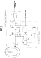
- Fig. 5 illustrates a block diagram showing another example of an apparatus for measuring a temperature using an optical fiber of the present invention.
- Example-2 omitted the pressure/flow rate regulator 32 which regulates the oxygen pressure, and no oxygen was supplied to the system. Instead, the pressure/flow rate regulator 31 adjusted the nitrogen gas flow rate to keep in a specified range.
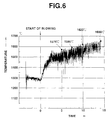
- Fig. 6 shows an example of the temperature measurement in a converter using an optical fiber under the condition given below.
- the waveform varying in vertical direction in Fig. 6 indicates the temperature measured by optical fiber, and the solid circles indicate the temperature determined by a thermocouple during intermittent sublance measurement for confirming the accuracy.
- the difference between a peak value measured by the optical fiber and a measured value using the thermocouple was 4°C at an average.
- the error of 4 °C for the measured temperature at 1600 °C corresponded to the accuracy of 0.25%, which was of considerably high accuracy as observed in Fig. 3.
- the optical fiber feed speed of 5 mm/sec. in continuous mode and the feed speed at 10 mm/sec. for 10 seconds followed by 20 seconds of non-feeding period in intermittent mode, nearly the same results were obtained.
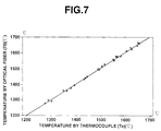
- Fig. 7 shows the relation between a thermocouple indication value (Ts) and an optical fiber thermometer indication value (Tf) drawn on a graph of Ts as vertical axis and Tf as horizontal axis.
- Ts thermocouple indication value
- Tf optical fiber thermometer indication value
- the observed values with optical fiber are expressed by open square symbol of " ⁇ ".
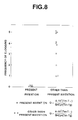
- Fig. 8 compares the frequency of stoppage of fiber feeding between the case that the blowing gas flow rate was kept to satisfy the equation(1) and the case of other conditions (where only nitrogen gas was supplied and without following the condition of the equation (1)). The figure shows that the mode of the present invention allows a stable measurement.
- the tip of the optical fiber covered with metallic tube is immersed directly into the high temperature liquid through the temperature measurement nozzle together with the supply of gas which prevents the nozzle from clogging, and the length of melted loss of the tip of the optical fiber is replaced with a new tip by continuously feeding the optical fiber, which provides an apparatus for measuring a temperature using an optical fiber while giving a continuous measurement of temperature for a long period with a quick response at a high accuracy.
- the gas which prevents the nozzle from clogging is supplied by selecting either one of an inert gas having an effect of cooling, a mixed gas of inert gas and oxygen, which mixed gas has an effect for melting mushroom and the like, or oxidizing gas, the tip of the nozzle is no more clogged with mushroom or the like and the feed of optical fiber does not become difficult.
- the ratio of the inside diameter of the nozzle for temperature measurement to the ouside diameter of the optical fiber covered with metallic tube is set in a range of from 1.5 to 3.5, the gas linear velocity blown from the tip of the temperature measurement nozzle is controlled at an adequate level in a range of from 50 to 500 Nm/sec.
- thermometer nozzle made of brick or ceramics or a temperature measurement nozzle made of a single metallic tube lined with ceramics inside thereof can be used, there is no possibility of accidental stoppage of optical fiber feed resulted by a fusion of the covering tube of the optical fiber with the temperature measuring tube.
- the nozzle for temperature measurement comrising a single metallic tube lined with ceramics inside thereof is further surrounded by a metallic tube to form a double-tube structure and since the gas which prevents the nozzle from clogging is blown through the gas between the inside nozzle for temperature measurement and the outside metallic tube, the durability of the temperature measurement nozzle is improved and a long period of operation of the nozzle is realized.
- an adequate control of the flow rate of the gas which prevents the nozzle clogging suppresses the formation of mushroom at the tip of the nozzle, so the long period of continuous temperature measurement of a high temperature liquid is available with a quick response and at a high accuracy.
- an end of an optical fiber covered with a metallic tube which is coiled inside of a drum in advance is sent out, passing through a temperature measurement nozzle and is immeresed into a high temperature liquid in a container continuously or intermittently.
- a radiation thermometer connected to another end of the optical fiber covered with a metallic tube measures a temperature of the high temperature liquid.
- a preventive gas is supplied to prevent the clogging of the nozzle.
- the nozzle 20 uses a ceramic pipe such as alumina pipe or a refractory made of mag-carbon (MgO-C) or the like having a through-hole, the nozzle sometimes breaks owing to thermal stress and thermal impact. In that case, the molten metal enters into the nozzle and clogs the nozzle, and finally the temperature measurement becomes unable to continue. Therefore, the present invention uses a metallic tube such as a stainless steel tube as the temperature measuring tube. To prevent the nozzle's clogging, an inert gas such as argon and nitrogen is supplied to the metallic tube.
- an inert gas such as argon and nitrogen is supplied to the metallic tube.
- a countermeasure to the generation of mushroom is to melt the formed mushroom by an oxygen blow, and to allow the feed of the optical fiber.
- the oxygen blow raises a problem of melt loss of the nozzle.
- a metal oxidation reaction occurs in the vicinity of the nozzle outlet to degrade the accuracy of measurement.
- the relation among temperature of gas, kind of gas, flow rate of gas, temperature of molten metal, composition of molten metel, and nozzle diameter satisfies at the same time the equation (1) and the equation (2) mentioned herein-before.
- the continuous temperature measurement is stably secured more preferrably for a long period while preventing the melt of the metallic tube .
- Temperature measurement is performed using an apparatus for measuring a tempertaure of a high temperature liquid shown in Fig. 5 illustrating Example-2 of the present invention.
- a clogging state of the temperature measurement nozzle 20 is judged based on a detected pressure value of the blown gas and a detected feed value of the optical fiber.
- the gas flow rate is controlled by a supply gas controller 33.
- the supply gas controller 33 sends a control signal to a pressure/flow ratw regulator 31 so as to satisfy the equation (2).
- Fig. 9 shows results of the temperature measurement in a converter using an optical fiber according to Example-3 of the present invention under the condition given below.
- the waveform varying in vertical direction in Fig. 9 indicates the temperature measured by optical fiber, and the solid circles indicate the temperature determined by a thermocouple during intermittent sublance measurement for confirming the accuracy.
- the difference between a peak value measured by the optical fiber and a measured value using the thermocouple was 4 °C at an average.
- the error of 4 °C for the measured temperature at 1600 °C corresponded to the accuracy of 0.25%, which was of a considerably high accuracy.
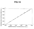
- Fig. 10 shows the relation between the thermocouple indication value (Ts) and the optical fiber thermometer indication value (Tf) drawn on a graph of Ts as vertical axis and Tf as horizontal axis.
- the observed values with optical fiber are expressed by open square symbol " ⁇ ".
- Fig. 11 compares the frequency of stoppage of (incapable of) fiber feeding between the case that the blown gas flow rate was kept to satisfy an eqution (2) and the case of other conditions (where only nitrogen gas was supplied and without following the condition of the eqution (2)). The figure shows that the mode of the invention allows a stable measurement.
- an end of an optical fiber covered with a metallic tube which is coiled inside of a drum in advance is sent out, passing through a temperature measurement nozzle and is immersed into a high temperature liquid in a container intermittently.
- a radiation thermometer connected to another end of the optical fiber covered with a metallic tube measures a temperature of the high temperature liquid.
- a gas which prevents the nozzle's clogging is supplied so as to prevent the clogging of the nozzle.
- the invention conducts an intermittent feed of the optical fiber covered with a metallic tube, the consumption of the optical fiber is significantly reduced and the operating cost is also reduced compared with the mode of continuous feed.
- operation of an ordinary converter a steel-making vessel to decarburize molten iron by blowing to produce molten steel
- the operating condition consumes as long as 9 m of the optical fiber under the condition of a continuous feeding mode at a feed speed of 10 mm/sec. If, in this case, the optical fiber is sent out for 10 seconds continuously, followed by 10 seconds of non-feeding time, or under an intermittent feeding mode, the consumption of the optical fiber is reduced to a half.
- the intermittent feed mode selects a cycle of 10 seconds of feeding and 20 seconds of no feeding
- the consumption of the optical fiber is reduced to one third.
- the intermittent feed mode selects a cycle of 5 seconds of feeding and 20 seconds of no feeding
- the consumption of the optical fiber is reduced to one fifth, which accounts to 2 m or less of consumed optical fiber for a single batch.
- the temperature measurement nozzle becomes high in temperature.
- a covering tube (metal) of the optical fiber contacts a metallic tube forming the nozzle to often induce fusion each other during a period of non-feeding of the optical fiber, which results in being incapable of the optical fiber feeding.
- the optical fiber feed means makes the optical fiber vibrate forward and backward along the direction of the feeding thereof during the period of no feeding of the optical fiber, so the fusion of metal is prevented and a stable temperature measurement is secured for a long period.
- Fig. 12 illustrates a block diagram showing an apparatus for measuring a temperature of a high temperature liquid using an optical fiber according to Example-4 of the present invetion.
- the apparatus of the present example is additionally equipped with a vibrator 51 for vibrating a metal-covered optical fiver 11 covered with a metallic tube and a vibration controller 52 forward and backward along the direction of the feeding.
- the supply gas controller 33 selects an inert gas (argon in Fig. 12) having a cooling effect, as the gas which prevents the nozzle clogging, so as to protect the metal-covered optical fiber 11 which has been inserted into the nozzle 20 and the furnace 40.
- an inert gas argon in Fig. 12
- Fig. 13 shows an example of the temperature measurement in a 10 ton converter using an optical fiber under the condition given below.
- the temperature measurement nozzle 20 was located at a level of 400 mm below a surface of the molten metal or lower on the side wall of the furnace.
- the waveform varying in vertical direction in Fig. 13 indicates the temperature measured by optical fiber.
- the solid circles indicate the temperature determined by a thermocouple during intermittent sublance measurement for confirming the accuracy.
- the period of low waveform height of measured temperature is the period of non-feeding the optical fiber.
- the difference between a peak value measured by the optical fiber and the measured value using the thermocouple was 4 °C at an average.
- the error of 4 °C for the measured temperature at 1600 °C corresponded to the accuracy of 0.25 %, which was of a considerably high accuracy.
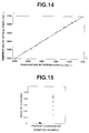
- Fig. 15 shows the relation between the thermocouple indication value (Ts) and the optical fiber thermometer indication value (Tf) drawn on a graph of Ts as vertical axis and Tf as horizontal axis.
- the observed values with optical fiber are expressed by open square symbol of " ⁇ ".
- Fig. 15 compares the frequency of stoppage of (incapable of) fiber feeding between the cases, during the period of non-feeding of optical fiber, that the optical fiber was vibrated at frequency of 180 /min. with the amplitude of ⁇ 5 mm and that no vibration was given.
- the figure shows that the mode of the invention allows stable measurement.
- a sealing device for preventing gas from leaking out of the optical fiber which passes through an optical fiber guide pipe is further equipped with an apparatus for measuring a temperature of a high temperature liquid using an optical fiber of the invention.
- the sealing device seals an optical fiber which is sent out through the optical fiber guide to the direction of the sending out the optical fiber.
- the sealing device comprises : plurality of sealing rubbers with a rubber hole made in each of them, the sealing rubbers being placed along with a direction of an optical fiber axis, and the rubber hole having a diameter less than that of the optical fiber ; a backing-up rings 3 built adjacently in between the sealing rubbers ; and a lantern ring 4 built in adjacent to each of the sealing rubbers. And sealing oil is forced into the backing-up ring by pressure.
- a body of the sealing device accommodates these sealing rubbers, backing-up ring and lantern ring inside of the sealing device.
- On both sides of the sealing device there are the optical fiber guide pipe jointed to the sealing device.
- the sealing device makes use of elasticity which is a nature of rubber.
- the sealing device prevents the gas leakage out of the optical fiber passing through the optical fiber guide pipe.
- the gas for preventing the nozzle clogging is made to flow into the optical fiber guide pipe by controlling both of a flow rate and a pressure and the gas is sent out from a tip end of the nozzle into the molten metal together with the optical fiber.
- the opticl fiber passes through the sealing rubbers with a narrow width(for example, 5 mm) and the rubber hole of a diameter(for example, 1.0 mm) smaller than a diameter(for example, 1.2 mm ) of the optical fiber, and the sealing device makes a sealing against the side the optical fiber enters.
- the seal device places plurality(for example, 4 pieces) of sealing rubbers which are narrow in width(for example, 5 mm) to improve its sealing feature and to reduce resistance against sliding movement.
- the backing-up ring built in between the sealing rubbers plays a role of preventing the sealing rubbers from being deformed.
- sealing oil is forced in between the sealing rubbers through the lantern ring by pressure to obtain lubrication work.
- the lubrication work reduces the resistance against the sliding movement of the optical fiber when it passes through the rubber hole of the sealing rubber.
- Fig. 16 is a section view illustrating a construction of the sealing device.
- a body of the sealing device has a hollow space formed.
- this hollow space there are sealing rubbers 2, backing-up rings 3 and optical fiber guide pipe 6 placed on both left and right sides of lantern ring 4 which is made as a center of their placement. Therefore, in the present example, there are 4 pieces of sealing rubbers 2.
- the sealing rubbers each have a ruber hole with a diameter of 1.0 mm in the center portion thereof, the diameter of the rubber hole is 1 mm slightly smaller than a diameter of 1.2 mm of the optical fiber 5.
- a thread cutting is given to both end sides of the body 1 of the sealing device and the optical fiber guide pipe 6 and a pressing 9 for sealing are respectively jointed to the body of the sealing device. Further to the pressing 9 a thread cutting is also given.
- the optical fiber guide pipe 6 on the feeding side of the optical fiber 5 is jointed to the pressing 9.
- the sealing oil 7 is forced through a sealing oil inlet 8 by backing pressure.
- the pressure makes a backing pressure to the sealing rubber 2 in respect of the gas pressure for preventing the nozzle clogging which furtherns the sealing effect.
- any oil having lubrication property can be available. If the rubber hole diameter of the sealing rubber 2 is smaller, the sealing feature is improved but the resistance against the passing movement of the optical fiber is increased which makes the feeding of the optical fiber impossible. Contrarily, if the hole diameter is larger, this makes a problem of the leakage.
- the hole diameter ranges preferably from 80 to 85 % of the diameter of the optical fiber.
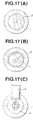
- Fig. 17 (A), (B) and (C) illustrates sectional views taken respectively on lines A-A, B-B and C-C of Fig. 16.
- the seal rubber 2 is forced to be expanded because the diameter with 1.2 mm of the optical fiber is larger than that with 1.0 mm of the rubber hole of the sealing rubber. Making use of a force of the sealing rubber which reacts the expansion, the gas leakage out of the optical fiber is prevented. In addition, the effect in sealing is increased the more becuse of the placement of the four pieces of the seal rubbers along with the axis direction of the optical fiber 5.
- the backing-up ring 3 is built in so as to supress the deformation of the sealing rubbers in the present example.
- the sealing rubbers are enabled to have an elastic movement or a reacting force or the like. And in respect of the lubrication, any oil will do for the sealing oil 7 which is forced in the lantern ring 4 by pressure.
- the sealing rubber is 5 mm long in width to reduce resistance against sliding movement and 4 pieces of the sealing rubbers 2 are parallelly placed to increase its sealing effect when the optical fiber passes through the sealing rubbers 2.
- the lantern ring 4 is set in between the sealing rubbers 2 and then, the sealing oil 7 is introduced through the sealing oil inlet 8 to further reduce the resistance against sliding movement of the optical fiber.
- the example of the sealing device works for sealing the reverse flow of the gas, which prevents the nozzle clogging, out of the optical fiber guide pipe 6 (the left hand side in Fig. 16). Thanks to this way of reducing the resistance of the sliding movement, the sealing to the optical fiber can be performed in a wide range of 50 to 800 mm / minite of feed speed of sending out the optical fiber. It should be noted that the feed speed is a speed at which the optical fiber passes by sliding movement.
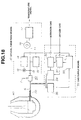
- Fig. 18 is a block diagram illustrating an application of an optical fiber sealing device (50) of Fig. 16 to an apparatus for measuring a temperature according to the present invention.
Landscapes
- Physics & Mathematics (AREA)
- General Physics & Mathematics (AREA)
- Spectroscopy & Molecular Physics (AREA)
- Radiation Pyrometers (AREA)
Applications Claiming Priority (10)
| Application Number | Priority Date | Filing Date | Title |
|---|---|---|---|
| JP249189/93 | 1993-10-05 | ||
| JP24918993 | 1993-10-05 | ||
| JP13038794A JP3166483B2 (ja) | 1993-10-05 | 1994-06-13 | 光ファイバーによる測温装置 |
| JP130387/94 | 1994-06-13 | ||
| JP06135394A JP3116728B2 (ja) | 1994-06-17 | 1994-06-17 | 光ファイバーによる高温液体の測温装置 |
| JP135394/94 | 1994-06-17 | ||
| JP147330/94 | 1994-06-29 | ||
| JP6147330A JPH0815040A (ja) | 1994-06-29 | 1994-06-29 | 光ファイバーによる高温液体の測温装置 |
| JP6219907A JPH07150215A (ja) | 1993-10-05 | 1994-09-14 | 光ファイバーのシール装置 |
| JP219907/94 | 1994-09-14 |
Publications (2)
| Publication Number | Publication Date |
|---|---|
| EP0646778A1 EP0646778A1 (en) | 1995-04-05 |
| EP0646778B1 true EP0646778B1 (en) | 1998-09-02 |
Family
ID=27527241
Family Applications (1)
| Application Number | Title | Priority Date | Filing Date |
|---|---|---|---|
| EP94115679A Expired - Lifetime EP0646778B1 (en) | 1993-10-05 | 1994-10-05 | Apparatus for measuring temperature using optical fiber and method therefor |
Country Status (6)
| Country | Link |
|---|---|
| US (1) | US5585914A (ref) |
| EP (1) | EP0646778B1 (ref) |
| KR (1) | KR0134654B1 (ref) |
| CN (1) | CN1064130C (ref) |
| DE (1) | DE69412955T2 (ref) |
| TW (1) | TW260742B (ref) |
Cited By (1)
| Publication number | Priority date | Publication date | Assignee | Title |
|---|---|---|---|---|
| DE10331124B3 (de) * | 2003-07-09 | 2005-02-17 | Heraeus Electro-Nite International N.V. | Verfahren und Vorrichtung zum Messen der Abkühlkurve von Schmelzenproben und/oder der Aufheizkurve von Schmelzenproben sowie deren Verwendung |
Families Citing this family (38)
| Publication number | Priority date | Publication date | Assignee | Title |
|---|---|---|---|---|
| US6004031A (en) * | 1993-11-30 | 1999-12-21 | Nkk Corporation | Temperature measuring device |
| JP2795146B2 (ja) * | 1993-11-30 | 1998-09-10 | 日本鋼管株式会社 | 測温用二重被覆光ファイバ |
| KR100348980B1 (ko) * | 1995-11-02 | 2003-04-11 | 미쓰비시 마테리알 가부시키가이샤 | 고온용체의온도측정방법과온도제어방법및이에사용되는온도측정장치 |
| AU746219B2 (en) * | 1995-11-02 | 2002-04-18 | Mitsubishi Materials Corporation | Temperature measuring apparatus |
| TW337553B (en) | 1995-12-20 | 1998-08-01 | Voest Alpine Ind Anlagen | Method for determination of electromagnetic waves originating from a melt |
| DE69722305T2 (de) * | 1996-04-09 | 2004-04-01 | Nkk Corp. | Vorrichtung zum Messen der Temperatur von geschmolzenem Metall |
| US5788374A (en) * | 1996-06-12 | 1998-08-04 | The United States Of America As Represented By The Secretary Of Commerce | Method and apparatus for measuring the temperature of a liquid medium |
| US5993902A (en) * | 1997-04-09 | 1999-11-30 | Seh America, Inc. | Apparatus and method for extending the lifetime of an exhaust sleeve for growing single crystal silicon by silicon nitride (SI3 N4) coating |
| US6067395A (en) * | 1997-05-15 | 2000-05-23 | Ocean Design, Inc. | Underwater bulkhead feedthrough assembly |
| WO1999023262A1 (en) * | 1997-11-04 | 1999-05-14 | Nkk Corporation | Method of operating blast furnace |
| US6321021B1 (en) | 1999-07-12 | 2001-11-20 | Ocean Design, Inc. | End seal assembly for tubular conduit |
| KR100617260B1 (ko) * | 1999-12-27 | 2006-08-29 | 주식회사 포스코 | 코크스오븐의 연소실 온도분포 측정장치 |
| TW558568B (en) * | 2000-06-12 | 2003-10-21 | Nippon Steel Corp | Method for observing inside of molten iron refining furnace and tuyere for observing inside of furnace |
| TW562866B (en) * | 2001-07-27 | 2003-11-21 | Nippon Steel Corp | Temperature measuring apparatus and method for molten metal |
| ITMI20012278A1 (it) * | 2001-10-30 | 2003-04-30 | Techint Spa | Dispositivo e metodo per misurazione discreta e continua della temperatura di metallo liquido in un forno o recipiente per la sua produzione |
| TW200615520A (en) * | 2004-11-09 | 2006-05-16 | Norm Pacific Automat Corp | Infrared thermometer |
| BRPI0502779B1 (pt) * | 2005-06-09 | 2020-09-29 | Usinas Siderúrgicas De Minas Gerais S.A. - Usiminas | Dispositivo para medição contínua de temperatura do aço líquido no distribuidor com pirômetro infravermelho e fibra óptica |
| DE102005061675B3 (de) | 2005-12-21 | 2007-07-26 | Betriebsforschungsinstitut VDEh - Institut für angewandte Forschung GmbH | Konverter mit einem Behälter zur Aufnahme geschmolzenen Metalls und einer Messvorrichtung zur optischen Temperaturbestimmung des geschmolzenen Metalls |
| GB2438214A (en) * | 2006-05-19 | 2007-11-21 | Heraeus Electro Nite Int | Measuring a parameter of a molten bath |
| DE102010020715A1 (de) * | 2010-05-17 | 2011-11-17 | Heraeus Electro-Nite International N.V. | Sensoranordnung zur Temperaturmessung sowie Verfahren zum Messen |
| JP5750339B2 (ja) * | 2011-08-31 | 2015-07-22 | 株式会社ニューフレアテクノロジー | 気相成長方法及び気相成長装置 |
| US9546909B2 (en) | 2013-02-08 | 2017-01-17 | Jyoti Goda | Apparatus and methods for continuous temperature measurement of molten metals |
| EP2799824B1 (en) * | 2013-04-30 | 2019-10-23 | Heraeus Electro-Nite International N.V. | Method and apparatus for measuring the temperature of a molten metal |
| AU2014250666C1 (en) * | 2013-04-30 | 2016-12-15 | Heraeus Electro-Nite International N.V. | Method and apparatus for measuring the temperature of a molten metal |
| EP2940441B1 (en) | 2014-04-30 | 2020-01-01 | Heraeus Electro-Nite International N.V. | Device for measuring the temperature of a molten metal |
| EP3051263A1 (en) * | 2015-01-28 | 2016-08-03 | Heraeus Electro-Nite International N.V. | Immersion device for an optical fiber for measuring the temperature of a melt |
| EP3051264B1 (en) | 2015-01-28 | 2017-11-15 | Heraeus Electro-Nite International N.V. | Immersion device for an optical fiber for measuring the temperature of a melt |
| TR201815134T4 (tr) * | 2015-01-28 | 2018-11-21 | Heraeus Electro Nite Int | Bir eriyiğin sıcaklığını ölçmeye yönelik bir optik elyaf için besleme cihazı. |
| GB2543318A (en) | 2015-10-14 | 2017-04-19 | Heraeus Electro Nite Int | Consumable optical fiber for measuring a temperature of a molten steel bath |
| CN105841832B (zh) * | 2016-04-01 | 2018-12-21 | 平高集团有限公司 | 一种实验用喷口及使用该喷口的灭弧室温度测量装置 |
| PL3290881T3 (pl) | 2016-09-01 | 2020-01-31 | Heraeus Electro-Nite International N.V. | Sposób wprowadzania przewodu z rdzeniem światłowodowym i układ zanurzeniowy umożliwiający przeprowadzenie sposobu |
| GB2558223B (en) * | 2016-12-22 | 2021-03-31 | Heraeus Electro Nite Int | Method for measuring a temperature of a molten metal bath |
| CN110285885A (zh) * | 2019-07-29 | 2019-09-27 | 湖南博云新材料股份有限公司 | 一种高温热处理炉红外测温系统 |
| EP4009019B1 (en) | 2020-12-02 | 2024-09-11 | Heraeus Electro-Nite International N.V. | Method and system for determining a temperature value of a molten metal bath |
| EP4009020A1 (en) * | 2020-12-02 | 2022-06-08 | Heraeus Electro-Nite International N.V. | Method and system for determining a series of temperature values of a molten metal bath |
| CN113310655B (zh) * | 2021-07-29 | 2022-04-26 | 中国空气动力研究与发展中心高速空气动力研究所 | 一种用于高超声速风洞的快速响应测温装置和测温方法 |
| ES2997486T3 (en) * | 2021-08-26 | 2025-02-17 | Heraeus Electro Nite Int | Measuring apparatus and method for measuring the temperature of a molten metal bath with an optical device |
| CN119935347B (zh) * | 2025-04-07 | 2025-08-05 | 中国科学院沈阳自动化研究所 | 一种用于测量熔融金属温度的装置 |
Family Cites Families (19)
| Publication number | Priority date | Publication date | Assignee | Title |
|---|---|---|---|---|
| FI55591C (fi) * | 1977-10-21 | 1979-08-10 | Nokia Oy Ab | Taetningshuvud foer ett behandlingsroer foer en kabel eller liknande |
| US4468771A (en) * | 1982-04-19 | 1984-08-28 | Institut Problem Litya Akademii Nauk Ukrainskoi Ssr | Light-guide unit for transmitting thermal radiation from molten metal to pyrometer |
| US4402790A (en) * | 1982-05-04 | 1983-09-06 | Bethlehem Steel Corporation | Coke oven flue temperature measuring process and probe machine |
| JPS60129628A (ja) * | 1983-12-16 | 1985-07-10 | Sumitomo Metal Ind Ltd | 溶鋼温度連続測定方法 |
| CA1218866A (en) * | 1984-04-24 | 1987-03-10 | John M. Lucas | Tuyere pyrometer |
| US4572487A (en) * | 1984-05-10 | 1986-02-25 | Inland Steel Company | Blast furnace tuyere with replaceable liner |
| GB8412219D0 (en) * | 1984-05-12 | 1984-06-20 | Smiths Industries Plc | Radiation-responsive apparatus |
| JPS6191529A (ja) * | 1984-10-11 | 1986-05-09 | Sumitomo Metal Ind Ltd | 溶融金属の温度測定装置 |
| BE902892A (fr) * | 1985-07-12 | 1986-01-13 | Centre Rech Metallurgique | Procede de mesure de la temperature d'un bain de metal dans un recipient metallurgique |
| JPS6219727A (ja) * | 1985-07-18 | 1987-01-28 | Japan Sensor Corp:Kk | 溶融金属の浸漬温度計 |
| JPS62132135A (ja) * | 1985-12-04 | 1987-06-15 | Sumitomo Metal Ind Ltd | 溶融金属温度連続測定方法 |
| US4786188A (en) * | 1986-02-27 | 1988-11-22 | Rosemont Inc. | Purge air system for a combustion instrument |
| US4836689A (en) * | 1986-02-27 | 1989-06-06 | Rosemount Inc. | Asymmetric purge air system for cleaning a lens |
| JPS62226025A (ja) * | 1986-03-28 | 1987-10-05 | Sumitomo Metal Ind Ltd | 製鋼炉の火点温度測定方法 |
| JPS63203716A (ja) * | 1987-02-19 | 1988-08-23 | Sumitomo Metal Ind Ltd | 溶銑の精錬制御方法 |
| JP2984337B2 (ja) * | 1990-08-09 | 1999-11-29 | 海洋科学技術センター | 光ファイバ水中温度分布測定システム |
| JP2897496B2 (ja) * | 1991-11-15 | 1999-05-31 | 日本鋼管株式会社 | 消耗形光ファイバ温度計 |
| JP2876881B2 (ja) * | 1992-03-02 | 1999-03-31 | 日本鋼管株式会社 | 溶融金属の温度測定装置及びレベル測定装置 |
| US5364186A (en) * | 1992-04-28 | 1994-11-15 | Luxtron Corporation | Apparatus and method for monitoring a temperature using a thermally fused composite ceramic blackbody temperature probe |
-
1994
- 1994-10-01 KR KR1019940025240A patent/KR0134654B1/ko not_active Expired - Fee Related
- 1994-10-04 US US08/317,376 patent/US5585914A/en not_active Expired - Fee Related
- 1994-10-05 DE DE69412955T patent/DE69412955T2/de not_active Expired - Fee Related
- 1994-10-05 CN CN94117907A patent/CN1064130C/zh not_active Expired - Fee Related
- 1994-10-05 EP EP94115679A patent/EP0646778B1/en not_active Expired - Lifetime
- 1994-10-08 TW TW083109355A patent/TW260742B/zh active
Non-Patent Citations (1)
| Title |
|---|
| English Abstract of JP-A-61091529 * |
Cited By (3)
| Publication number | Priority date | Publication date | Assignee | Title |
|---|---|---|---|---|
| DE10331124B3 (de) * | 2003-07-09 | 2005-02-17 | Heraeus Electro-Nite International N.V. | Verfahren und Vorrichtung zum Messen der Abkühlkurve von Schmelzenproben und/oder der Aufheizkurve von Schmelzenproben sowie deren Verwendung |
| US7384192B2 (en) | 2003-07-09 | 2008-06-10 | Heraeus Electro-Nite International N.V. | Method for measuring cooling/heating curves of molten masses |
| US7635220B2 (en) | 2003-07-09 | 2009-12-22 | Heraeus Electro-Nite International N.V. | Device for measuring cooling/heating curves of molten masses |
Also Published As
| Publication number | Publication date |
|---|---|
| US5585914A (en) | 1996-12-17 |
| KR950012047A (ko) | 1995-05-16 |
| TW260742B (ref) | 1995-10-21 |
| CN1111751A (zh) | 1995-11-15 |
| DE69412955D1 (de) | 1998-10-08 |
| DE69412955T2 (de) | 1999-02-25 |
| EP0646778A1 (en) | 1995-04-05 |
| KR0134654B1 (ko) | 1998-04-20 |
| CN1064130C (zh) | 2001-04-04 |
Similar Documents
| Publication | Publication Date | Title |
|---|---|---|
| US5585914A (en) | Apparatus and method for measuring a temperature of a high temperature liquid contained in a furnace | |
| US9500528B2 (en) | Method for maintaining a temperature of a metal melt | |
| US4651976A (en) | Method for operating a converter used for steel refining | |
| US4345746A (en) | Apparatus for refining ferrous melt with slag conditioning | |
| CA1250356A (en) | Method and apparatus for measuring slag-forming conditions within converter | |
| JP3166483B2 (ja) | 光ファイバーによる測温装置 | |
| JPH0394129A (ja) | 溶融金属温度連続測定装置 | |
| JP3175510B2 (ja) | 光ファイバーによる高温液体の測温装置 | |
| CA1337920C (en) | Process for detecting outflow of slag | |
| JP3351120B2 (ja) | 光ファイバ温度計による出銑口での溶銑温度測定法 | |
| JPH0815040A (ja) | 光ファイバーによる高温液体の測温装置 | |
| JP3214234B2 (ja) | 光ファイバーによる高温液体の測温装置 | |
| JP2803534B2 (ja) | 転炉の吹錬制御方法 | |
| JPH07173516A (ja) | 転炉の操業方法 | |
| AU757791B2 (en) | Method for observing inside of molten iron refining furnace and tuyere for observing inside of furnace | |
| JP2822875B2 (ja) | 溶融金属温度測定装置 | |
| JPH085465A (ja) | 光ファイバーによる高温液体の測温装置 | |
| JPH0464419B2 (ref) | ||
| JPS6252423A (ja) | 溶融金属温度連続測定方法及び装置 | |
| JPS63214627A (ja) | 溶融金属の測温方法 | |
| JPS63230815A (ja) | 精錬用羽口 | |
| WO2025171108A1 (en) | Systems and methods to measure oxidation losses of furnace electrodes | |
| FI71841B (fi) | Enmetod foer temperaturmaetning av smaelt material | |
| JPH0569454B2 (ref) | ||
| JPS5776117A (en) | Control of bottom blow gas at converter having bottom blowing function |
Legal Events
| Date | Code | Title | Description |
|---|---|---|---|
| PUAI | Public reference made under article 153(3) epc to a published international application that has entered the european phase |
Free format text: ORIGINAL CODE: 0009012 |
|
| 17P | Request for examination filed |
Effective date: 19941005 |
|
| AK | Designated contracting states |
Kind code of ref document: A1 Designated state(s): DE FR GB |
|
| 17Q | First examination report despatched |
Effective date: 19961029 |
|
| GRAG | Despatch of communication of intention to grant |
Free format text: ORIGINAL CODE: EPIDOS AGRA |
|
| GRAG | Despatch of communication of intention to grant |
Free format text: ORIGINAL CODE: EPIDOS AGRA |
|
| GRAH | Despatch of communication of intention to grant a patent |
Free format text: ORIGINAL CODE: EPIDOS IGRA |
|
| GRAH | Despatch of communication of intention to grant a patent |
Free format text: ORIGINAL CODE: EPIDOS IGRA |
|
| GRAA | (expected) grant |
Free format text: ORIGINAL CODE: 0009210 |
|
| AK | Designated contracting states |
Kind code of ref document: B1 Designated state(s): DE FR GB |
|
| REF | Corresponds to: |
Ref document number: 69412955 Country of ref document: DE Date of ref document: 19981008 |
|
| ET | Fr: translation filed | ||
| PLBE | No opposition filed within time limit |
Free format text: ORIGINAL CODE: 0009261 |
|
| STAA | Information on the status of an ep patent application or granted ep patent |
Free format text: STATUS: NO OPPOSITION FILED WITHIN TIME LIMIT |
|
| 26N | No opposition filed | ||
| REG | Reference to a national code |
Ref country code: GB Ref legal event code: IF02 |
|
| PGFP | Annual fee paid to national office [announced via postgrant information from national office to epo] |
Ref country code: GB Payment date: 20031001 Year of fee payment: 10 |
|
| PGFP | Annual fee paid to national office [announced via postgrant information from national office to epo] |
Ref country code: FR Payment date: 20031003 Year of fee payment: 10 |
|
| PGFP | Annual fee paid to national office [announced via postgrant information from national office to epo] |
Ref country code: DE Payment date: 20031016 Year of fee payment: 10 |
|
| PG25 | Lapsed in a contracting state [announced via postgrant information from national office to epo] |
Ref country code: GB Free format text: LAPSE BECAUSE OF NON-PAYMENT OF DUE FEES Effective date: 20041005 |
|
| PG25 | Lapsed in a contracting state [announced via postgrant information from national office to epo] |
Ref country code: DE Free format text: LAPSE BECAUSE OF NON-PAYMENT OF DUE FEES Effective date: 20050503 |
|
| GBPC | Gb: european patent ceased through non-payment of renewal fee |
Effective date: 20041005 |
|
| PG25 | Lapsed in a contracting state [announced via postgrant information from national office to epo] |
Ref country code: FR Free format text: LAPSE BECAUSE OF NON-PAYMENT OF DUE FEES Effective date: 20050630 |
|
| REG | Reference to a national code |
Ref country code: FR Ref legal event code: ST |