EP0644960B1 - Arrangement for heating a running thread - Google Patents
Arrangement for heating a running thread Download PDFInfo
- Publication number
- EP0644960B1 EP0644960B1 EP93912889A EP93912889A EP0644960B1 EP 0644960 B1 EP0644960 B1 EP 0644960B1 EP 93912889 A EP93912889 A EP 93912889A EP 93912889 A EP93912889 A EP 93912889A EP 0644960 B1 EP0644960 B1 EP 0644960B1
- Authority
- EP
- European Patent Office
- Prior art keywords
- thread
- heating
- carriers
- heating device
- thread carriers
- Prior art date
- Legal status (The legal status is an assumption and is not a legal conclusion. Google has not performed a legal analysis and makes no representation as to the accuracy of the status listed.)
- Expired - Lifetime
Links
- 238000010438 heat treatment Methods 0.000 title claims abstract description 236
- 238000004140 cleaning Methods 0.000 claims abstract description 23
- 239000000969 carrier Substances 0.000 claims description 54
- 230000005855 radiation Effects 0.000 claims 2
- 230000000694 effects Effects 0.000 abstract description 10
- 229920001169 thermoplastic Polymers 0.000 abstract description 3
- 239000004416 thermosoftening plastic Substances 0.000 abstract description 3
- 230000001105 regulatory effect Effects 0.000 abstract description 2
- 238000013021 overheating Methods 0.000 abstract 1
- 238000012546 transfer Methods 0.000 description 25
- 238000002788 crimping Methods 0.000 description 9
- 230000008901 benefit Effects 0.000 description 8
- 230000008859 change Effects 0.000 description 7
- 238000013461 design Methods 0.000 description 7
- 238000000034 method Methods 0.000 description 5
- 230000008569 process Effects 0.000 description 5
- 241001589086 Bellapiscis medius Species 0.000 description 4
- 238000001816 cooling Methods 0.000 description 4
- 230000001419 dependent effect Effects 0.000 description 4
- 230000006872 improvement Effects 0.000 description 3
- 239000000463 material Substances 0.000 description 3
- 229910052751 metal Inorganic materials 0.000 description 3
- 239000002184 metal Substances 0.000 description 3
- 239000011324 bead Substances 0.000 description 2
- 230000007423 decrease Effects 0.000 description 2
- 238000006073 displacement reaction Methods 0.000 description 2
- 238000004519 manufacturing process Methods 0.000 description 2
- 238000005457 optimization Methods 0.000 description 2
- 238000012545 processing Methods 0.000 description 2
- 238000005476 soldering Methods 0.000 description 2
- 125000006850 spacer group Chemical group 0.000 description 2
- 239000012815 thermoplastic material Substances 0.000 description 2
- 238000007514 turning Methods 0.000 description 2
- 229910000838 Al alloy Inorganic materials 0.000 description 1
- 239000004952 Polyamide Substances 0.000 description 1
- 229910000831 Steel Inorganic materials 0.000 description 1
- GWEVSGVZZGPLCZ-UHFFFAOYSA-N Titan oxide Chemical compound O=[Ti]=O GWEVSGVZZGPLCZ-UHFFFAOYSA-N 0.000 description 1
- 238000005299 abrasion Methods 0.000 description 1
- JRBRVDCKNXZZGH-UHFFFAOYSA-N alumane;copper Chemical compound [AlH3].[Cu] JRBRVDCKNXZZGH-UHFFFAOYSA-N 0.000 description 1
- 238000013459 approach Methods 0.000 description 1
- 230000009286 beneficial effect Effects 0.000 description 1
- 230000033228 biological regulation Effects 0.000 description 1
- 230000005540 biological transmission Effects 0.000 description 1
- 238000005336 cracking Methods 0.000 description 1
- 230000003247 decreasing effect Effects 0.000 description 1
- 238000011161 development Methods 0.000 description 1
- 238000009826 distribution Methods 0.000 description 1
- 239000013013 elastic material Substances 0.000 description 1
- 238000005516 engineering process Methods 0.000 description 1
- 239000011888 foil Substances 0.000 description 1
- 238000003780 insertion Methods 0.000 description 1
- 230000037431 insertion Effects 0.000 description 1
- 239000011810 insulating material Substances 0.000 description 1
- 238000003754 machining Methods 0.000 description 1
- HCWCAKKEBCNQJP-UHFFFAOYSA-N magnesium orthosilicate Chemical compound [Mg+2].[Mg+2].[O-][Si]([O-])([O-])[O-] HCWCAKKEBCNQJP-UHFFFAOYSA-N 0.000 description 1
- 239000000395 magnesium oxide Substances 0.000 description 1
- CPLXHLVBOLITMK-UHFFFAOYSA-N magnesium oxide Inorganic materials [Mg]=O CPLXHLVBOLITMK-UHFFFAOYSA-N 0.000 description 1
- 239000000391 magnesium silicate Substances 0.000 description 1
- 229910052919 magnesium silicate Inorganic materials 0.000 description 1
- 235000019792 magnesium silicate Nutrition 0.000 description 1
- AXZKOIWUVFPNLO-UHFFFAOYSA-N magnesium;oxygen(2-) Chemical compound [O-2].[Mg+2] AXZKOIWUVFPNLO-UHFFFAOYSA-N 0.000 description 1
- 238000005259 measurement Methods 0.000 description 1
- TWNQGVIAIRXVLR-UHFFFAOYSA-N oxo(oxoalumanyloxy)alumane Chemical compound O=[Al]O[Al]=O TWNQGVIAIRXVLR-UHFFFAOYSA-N 0.000 description 1
- 230000002093 peripheral effect Effects 0.000 description 1
- 229920002647 polyamide Polymers 0.000 description 1
- -1 polyethylene terephthalate Polymers 0.000 description 1
- 229920000139 polyethylene terephthalate Polymers 0.000 description 1
- 239000005020 polyethylene terephthalate Substances 0.000 description 1
- 239000000843 powder Substances 0.000 description 1
- 230000028327 secretion Effects 0.000 description 1
- 239000010959 steel Substances 0.000 description 1
- 239000000126 substance Substances 0.000 description 1
- 239000013589 supplement Substances 0.000 description 1
- 230000001360 synchronised effect Effects 0.000 description 1
- 239000002470 thermal conductor Substances 0.000 description 1
- OGIDPMRJRNCKJF-UHFFFAOYSA-N titanium oxide Inorganic materials [Ti]=O OGIDPMRJRNCKJF-UHFFFAOYSA-N 0.000 description 1
- 230000007704 transition Effects 0.000 description 1
- 238000011144 upstream manufacturing Methods 0.000 description 1
- 238000004804 winding Methods 0.000 description 1
Images


Classifications
-
- D—TEXTILES; PAPER
- D02—YARNS; MECHANICAL FINISHING OF YARNS OR ROPES; WARPING OR BEAMING
- D02J—FINISHING OR DRESSING OF FILAMENTS, YARNS, THREADS, CORDS, ROPES OR THE LIKE
- D02J13/00—Heating or cooling the yarn, thread, cord, rope, or the like, not specific to any one of the processes provided for in this subclass
Definitions
- the invention relates to a heating device, in particular a elongated body, such as B. a heating tube for heating a running thread.
- Such a heater finds e.g. Use on a false twist crimping machine.
- Devices for heating running chemical threads in false twist crimping processes are known. Generally they have rails those in elongated, heatable to a certain temperature Heating chambers are located, and over which a thread over thread carriers, so-called Webs that can be guided to be heated.
- tubular thread overflow body For stretching and thermally fixing synthetic threads tubular thread overflow body known.
- the DE-AS 13 03 384 an overflow body, which is wrapped by the thread becomes.
- This overflow body has a rotationally symmetrical Form on and is provided with a bead at the end of the thread and from its thread run-up to its thread run-off end from the Thread stretching - continuously increasing to the thread fixing temperature heatable and designed and arranged so that it from the thread in Form of a steep thread can be wrapped.
- This thread overflow body is complicated in structure and requires for its manufacturing a multitude of expensive steps. In addition he should not be using the modern high-speed process reliability.
- thermoplastic material for the thread comes in particular Polyamide or polyethylene terephthalate (PA6, PA6.6) into consideration, however without limitation to these materials.
- EP 0 442 368 A1 also describes a heater for a synthetic yarn known, the thread carrier kept above the self-cleaning temperature become. With this heater, the thread is curved in one plane along the heating surface out and the thread carriers are on by additional heating devices maintained the desired high temperature.
- the object of the invention is to provide a heating device which is easy to manufacture and which high temperatures of all components can be operated, and at which in particular uses the self-cleaning effects effectively can.
- the width of the thread overflow webs Vary the dwell time of a thread on the heating surface. This means, by the size of the heated surface on which the thread lies is changed, the one transferred to the thread also changes Warmth.
- the heat transfer is adjustable. Another possible variation is given by webs that are variable in height, which allow the distance between the heating surface itself and the thread track set uniformly or variably.
- the thread overflow lengths can be changed in that Thread running direction immediately in front of and behind the heating element be provided in their position relative to the radiator and / or are mutually adjustable. If necessary, these Thread guide but also at the entrance and exit of the radiator itself be provided.
- Heating device can be operated in a temperature range, which is the self-cleaning temperature of the heated surface corresponds.
- the invention makes use of the knowledge that the Self-cleaning temperature in the order of approximately 430 degrees Celsius lies, and that about the influence of the heat transfer of the heated surface on the thread to be heated the thread a lower temperature e.g. Exposed to 330 degrees Celsius becomes.
- This option is particularly useful if a heating device is provided for several threads to be heated.
- a heating device is provided for several threads to be heated.
- one of the thread heating zones during the cleaning phase other thread in its associated thread heating zone continuously continue to run without the self-cleaning of the first thread heating zone an impact on the quality of the thread still running in the second thread heating zone.
- This heating device is described in EP 0 412 429 A2.
- This heating device is its high heating output, which is transferable to the thread and a short length of Heater allowed.
- the other advantage is the self-cleaning effect.
- An additional object of the invention with regard to this particular Embodiment is to continue the known heater To design that a cleaning of the heater from baked or Cracked residues of the thermoplastic thread material are not required becomes.
- the heater have an entrance area in which the thread is only slight or has no contact with thread carriers by only holding the thread carriers there be arranged at a large distance.
- the Entrance area only with an entrance thread guide and the exit area only equipped with a starting thread guide.
- the input thread guide is cold remains.
- the input thread guide has no thermal contact with the heating surface. This keeps the thread guide essentially cold so that it does not secretions of thermoplastic material can occur.
- the thread guide on the output side is said to be self-cleaning to have. It is therefore preferably directly with the heating surface connected and lies at the beginning of the so-called "rule section", the adjoins the entrance area.
- the control section is the section in which the thread reaches its set temperature receives.
- the thread carrier in the control section ensures that the thread with a precisely definable distance from the Heating surface is performed.
- the heating device receives a gradation between the input section and the control section, such that the distance of the heating surface in the entrance section of the thread path is larger, preferably a multiple of that Distance is that the thread path in the control section of the Heating surface.
- the arrangement of the thread carriers according to the invention ensures that that the thread carriers are only arranged in the zone in which the temperature of the thread reached on the one hand and the heater temperature on the other hand, ensure self-cleaning.
- In the control area there is an exact temperature control of the heating device, namely preferably by regulation. Due to the precise guidance of the thread, relative to the heater, it ensures that the thread assumes the specified target temperature. It can be variable Widths of the thread carriers with respect to a running thread with movable ones Thread carriers the so-called dwell time of the thread in wide Limits are kept changeable, d. H. the interface between Thread and thread carrier is depending on the thread or on Radiator measured temperatures set. In the entrance section the exact guidance of the thread is dispensed with. Here is from made use of the knowledge that the Heating the thread with large temperature gradients between Heating device and thread takes place and therefore an exact temperature control the thread is neither wanted nor possible.
- the heating of the thread in the control area causes the The outer layers of the thread assume the desired temperature. However, uniform heating of the thread is required its entire cross section. This goal is achieved in that the control section is followed by an end section in which again thread carrier with a large distance or no thread carrier is arranged. To avoid the thread in contact with the Heating surface of the heating device should also be preferred here the distance between the thread path and the heating surface is larger, preferably be a multiple of the distance, which thread run and Have a heating surface in the control range. By this arrangement of the End section ensures that with little heat transfer Heat loss can be prevented and an even distribution the heat supplied in the control section over the entire Thread cross-section takes place.
- a large, unsupported length of thread can be purchased in the entrance section be taken; it turned out that in the entrance section the tendency of the thread to oscillate is low.
- a Length of 400 mm - 500 mm is possible. The length should, however Limitation of the effort to be extended to what Achieving the desired preheating of the thread is necessary.
- the end section is in any case shorter than the entrance section.
- the length of the end section is preferably limited to 300 mm and should be even shorter in particular.
- the distance between the thread run and the heating surface in the end section and in the entrance section is larger, preferably a multiple of that Distance in the control range, but preferably also limited to 5 mm, preferably 3 mm.
- the optimization of the heating effect on the thread is of great importance Significance for the quality of the thread and its texturing in the False twist crimping machine. For this reason it is proposed that the touch length of the thread carrier is adjustable. This can also an optimal setting of the heating effect on each desired thread speed and thread diameter (titer) respectively.
- a heater can e.g. B. the shape have a pipe, on the circumference of which there are several in the circumferential direction in their axial extension widening webs are provided. These webs can be successively arranged offset on the circumference be. It is thereby achieved that the screw-wrapping around the tube Thread touches the webs one after the other in areas which the webs have essentially the same contact length.
- Another embodiment that can be adjusted at any time Heating effect on the specific process parameters, especially thread titer and running speed allowed consists of a through Composed sections of radiators variable in length.
- the Possibility of an essentially smooth surface Heating tube to put a sleeve or a cage corresponds to the outside diameter of the heating pipe and its mantle through recesses lined up in rows same shape is permeated.
- the inside diameter corresponds to the outside diameter of the heating pipe and its mantle through recesses lined up in rows same shape is permeated.
- the lines run parallel to the axis.
- Recesses correspond to the shape of the recesses uniform circumferentially extending webs. The cuff is secured on the heating pipe against axial displacement, can but be rotated.
- this has the advantage that by gradually turning the cuff on the tube of thread can always be run over a clean overflow point of the webs; on the other hand, the thread through the different design the webs are heated in wide temperature ranges. Because in the cuff has uniform webs or recesses diametrically opposite or repeating at certain angular intervals, overflow paths for two or more threads are formed. in the the rest are those between the rows in the longitudinal direction of the cuff extending webs of no importance for the essence of the invention.
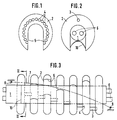
- the heating device shown in Figure 3 has a tube 1, hereinafter Heating tube, on.
- the heating tube 1 carries two in its interior parallel heating resistors 6, preferably from each other and from the inner surface of the heating tube 1 of a suitable insulating material such as magnesium oxide or magnesium silicate powder are separated.
- the heating tube 1 consists of a good heat-conducting metal, such as steel or preferably made of a copper-aluminum alloy.
- the disks shown in Figures 1 and 2 in detail 2 are circular and provided with a radial slot 5, the clear width essentially the diameter of the heating tube 1 corresponds and its opposite edges parallel to each other lie.
- the outer edge of the discs 2 is spherical.
- the spherical edges of the disks 2 serve to guide a thread 7, via an input thread guide 8 to those of the crowned Edges of the disks 2 formed thread overflow surface of the heating device is placed and this is angled to the thread carrier 8 and axially offset starting thread guide 9 leaves. That is, the Thread 7 wraps around the device in a spiral, the slope depends on the offset of the thread carriers 8 and 9 to each other. At least one of the thread carriers is relative to the other around the Axis of the heating tube 1 pivotable so that the length of the Thread path over the disks 2 by changing the slope of the can be changed by the thread 7 formed helix.
- the positions of the Thread carriers 8 and 9 are on both sides of the slots 5 and The helix of the thread 7 is located outside the slots 5 Area of the washers 2.
- the disks are made of a heat and scale resistant Material, e.g. B. aluminum oxide or titanium oxide.
- a heat and scale resistant Material e.g. B. aluminum oxide or titanium oxide.
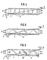
- the embodiment of the invention shown in Fig. 4 consists of one provided with an electrical heating resistor wire 6 Heating tube 1, which is surrounded by a plurality of rings 2.
- the Rings 2 are fixed to the heating tube 1, for example by soldering connected and are equidistant from each other.
- the rings 2 can also be formed by beads that are in regular Gaps in the tube.
- the rings can too be spaced apart by grooves that are in the outer jacket of the heating tube 1 are incorporated.
- the radially protruding circumferential surface the ring 2 is crowned and is more thread-friendly Nature.
- the rings 2 serve a thread 7 at a distance to lead over the lateral surface of the heated tube 1, the Thread overflow path is preferably helical around tube 1 loops.
- thread guides 8 and 9 are at both ends of the heating tube 1 thread guides 8 and 9, their offset with respect to each other Determine the slope and length of the thread path. At least one the two thread guides can be adjusted with respect to the other.
- the means necessary to adjust this thread guide include to the state of the art and are not shown.
- the embodiment of the invention shown in Fig. 5 consists of a heating tube 1 which has an electrical resistance heating wire in its interior 6 and that over its entire length of is surrounded by a helical thread carrier 2.
- the helical one Thread carrier 2 is z. B. by soldering firmly to the tube 1 connected. Its outward-facing surface is spherical and of thread-friendly nature, d. that is, it exercises on an overflowing Thread out a negligible friction.
- the thread 7 will here guided in a helix that corresponds to the gears of the thread carrier 2 is opposite.
- the thread is 8 by means of eyelet-shaped thread guide and 9, which are provided at the run-up and drain end of the heating tube 1 are placed on the helical thread carrier 2. Like the already described embodiments, it is possible to use the thread guide 8.9 to be adjusted relative to each other.
- FIG. 6 A fourth embodiment of the invention is shown in FIG. 6. This is also a heater 6 heated by a heating resistor Tube 1.
- tube 1 is of a helical shape
- the thread carrier 2 can be, for example Be metal tube, its surface lying against the heating tube 1 is flattened so that there is close thermal contact between the heating tube 1 and the thread carrier 2.
- the thread overflow heaters described here offer u. a. the Advantages of variable thread overflow paths within wide limits enable. Furthermore, can be held in a row several differently heated thread carriers over the length of one Thread path realize variable temperature profiles.
- FIGS. 7-9 and 11-15 show heating devices those at the thread inlet and at the thread outlet of the heating tube 1 Input thread guide 8 and an output thread guide 9 sit, and at of the thread carriers 8, 9 and the tube 1 in the circumferential direction of the Tube are rotatable relative to each other.
- only the starting thread guide is 9 rotatable relative to the tube while the input thread guide 8 sits stationary.
- the starting thread guide 9 is seated, formed by the notch 16, coaxial and rotatable on the lower one End of the heating tube 1 and is in the rotating area 15 relative to Tube rotatable.
- the heating tube 1 is a has electrical resistance heating, which over the electrical Supply lines 6a is supplied with the heating current.
- Figures 7-9 and 11-14 show that the heating devices at the entrance of the heating pipe 1 and / or at the exit of the heating pipe 1 each have an input section 11 or end section 12 can of the passing thread 7 a greater radial distance than the outer surface of the heating tube 1 occupies.
- Rule section 13 is another special feature in the present case having.
- the thread 7 can consequently at any point within the predetermined Angular range run, depending on the particular Rotary position of the thread guides 8, 9 and the tube 1 relative to each other.
- the rings point in the angular range that can be covered by the thread 7 a changing ring width in the circumferential direction.
- the width B of a ring depends on a circumferential coordinate u after a function B (u) changes each can be predetermined.
- the function is linear.
- Figure 9 shows the peculiarity that the rings 2 in the possible contact area with the thread 7 in the circumferential direction have changing height H.
- the height H is a function of the circumferential coordinate u, correspondingly with H (u) is designated.
- the width B of the rings is in the circumferential direction in which the height H of the rings decreases. It is therefore to be expected that with increasing contact time of thread 7 on the rings due to the increasing ring width B also in the non-contact longitudinal areas between the rings 2 the heat flow on the thread due to the decreasing at the same time Distance between thread 7 and tubular jacket increases.
- Figures 7 and 8 show that the rings 2 also then in the angular range that can be covered by the thread one in the circumferential direction may have changing height if the Width of the rings 2, i.e. the web width, not in the circumferential direction changes.
- the rings can also result from that annular grooves are machined into the tubular jacket in such a way that the rings according to the invention, on which the thread 7 runs, stand stay.
- the heat transfer from the heating tube 1 to the thread 7 takes place on the one hand at the contact zones which connect the rings 2 with the thread 7 form.
- the total heat flow acting on the thread becomes one Function of the thread path geometry set in relation to the Be tube geometry, because the contact lengths and the non-contact Longitudinal areas, like the ring height, depend on the Relative position of the input thread guide 8 or the output thread guide 9 to the heating pipe 1.
- Rings 2 are eccentric with respect to the tube axis 17, wherein advantageous the rings in pairs by 180 degrees to each other are offset.
- the heating device is symmetrical with respect to the tube axis 17 is, which makes them one for machining and processing Pair of running threads 7.1, 7.2 is suitable.
- FIG. 11 also shows a heating device 13, which is a delivery unit 18 is arranged upstream and that the heating device 13 has a cooling zone, the is designed here as a cooling rail 19, and a false twister 20 and a delivery plant 21 are arranged downstream.
- a heating device 13 which is a delivery unit 18 is arranged upstream and that the heating device 13 has a cooling zone, the is designed here as a cooling rail 19, and a false twister 20 and a delivery plant 21 are arranged downstream.
- FIG. 11 further shows that the input thread guide 8 and the Exit thread guide 9 relative to one another or relative to the heating tube 1 as a function of that measured at the output of the heating device 13 Thread temperature are adjustable. This is used in the exit area of the heating tube 1 arranged temperature sensor 22, the one Output signal delivers, e.g. via a stepper motor 23 each Input thread guide 8 or output thread guide 9 depending on the temperature to adjust. It should be expressly said that the measurement signal of the Temperature sensor 22 also be superimposed on a thread tension signal can, which is generated by the tensile force measuring device 24, and behind the heater.
- the present invention offers the essentials Advantage that the effective heat transfer from the heater extremely sensitive on the thread in the sense of process optimization can be set, and that in addition a very precise control of the thread temperature can be made to over the to achieve an optimal thread quality over the entire length of the thread.
- FIGS. 12-14 also show additional exemplary embodiments the invention.
- a plurality of webs 2 are transverse to Thread running attached to the heated surface, the Height of the webs the heated surface by at least 0.1 millimeter, but not more than 5 millimeters tall.
- the height of the webs 2 is above the heated one Surface is no more than about 5 millimeters around the Advantages of this heater according to the invention, in particular the Self-cleaning and the sensitive controllability, individually or simultaneously to be able to exploit.
- the thread heating zone is convex towards the thread curved, allowing the thread to be on a Helix line can be passed over the thread heating zone.
- the tube can be used as a rotating body, rotating body section or rotating body segment be trained to easily run a thread to reach along a spiral line.
- left thread heating zone also be a single thread line, e.g. if an adjustability the thread path is not provided relative to the heated surface.
- the filament heating zone according to FIG. 13 shows an angular range within a thread of which are guided relative to the heated surface can.
- FIG. 13 shows, it can also be useful to have only one of the filament heating zones with rings whose width B is in The circumferential direction changes, analogously to the predicted, the height H, while the ring width B in the other of the two filament heating zones is kept constant.
- the height H of the Rings to vary in the circumferential direction, and then of course a relative adjustability between the heated surface and the running thread makes sense.
- Thread heating zones make sense if you use these thread heating zones in each case synchronously movable input thread guide 8 or output thread guide 9 assigns which thread guides 8 and 9 in the end areas rotatable thread guide lever 26 sit.
- the synchronous mobility can be achieved using a corresponding gear can be easily realized.
- a transmission is part of the State of the art and shall not be explained in more detail here.
- Thread heating zones 25a, 25b it is possible to have two Thread heating zones 25a, 25b to be arranged diametrically to one another, and in in this case, the input thread guide 8 or output thread guide 9 so to arrange on the respective thread carrier levers 26 that the threads run at locations with the same operating conditions.
- the width B of the rings may also be possible the width B of the rings to change gradually. This means that the width B in pieces is constant and gradually at certain circumferential coordinates, e.g. from a smaller width to a larger width.
- the invention is also intended to include that the height H changes gradually in the circumferential direction e.g. To get thread running areas, within which a small lateral fluctuation of the contact zone between thread and ring in essentially without influence on the heat transfer between heated Surface and thread remains.
- rings can be changed Width and / or height in the circumferential direction against each other are staggered that in anticipation of any thread running the effective contact zones essentially the same contact times or Allow thread clearances to the outer jacket of the tube.
- a gradual changing ring height H is easy to realize if you have rings provides which sectors have a constant Radius per sector.
- the transition area between two neighboring ones Sectors of different radii must then be designed to be thread-friendly, i.e. abrupt or edgy changes in the respective ring radius on the adjacent ring radius are corresponding in the circumferential direction round to avoid damage to the thread.
- FIGS. 15d and 15e show eccentrically arranged ones Crosspieces 2.
- the crosspieces 2 are circular, the center of the circle of the Web 2 with respect to the center of the circle of the heating tube 1 around Eccentricity 27 is offset.
- Entry thread guide and exit thread guide are for each thread arranged separately on a thread carrier lever 26, namely circumferentially with respect to the center of the ring 2 in the sense same effect on the heated thread rotatable.
- FIG. 15e shows the one rotated by 180 degrees 15d represents a situation optimal influence of the heat transfer from the heating tube 1 to the Thread 7 can be reached:
- those provided according to the invention can be used Wrestle on the heated surface without further self-cleaning temperatures drive while the temperatures are on the thread act, allow damage-free heating.
- the invention enables filament yarns to be different Titer, e.g. 22 dtex (20 den.) Or 44 dtex (40 den.) With the same heating device and to process simultaneously, provided the relative position between the running thread and the heated surface set accordingly becomes.
- one and the same heating device can be used without Change or adjust the temperature of the heated surface different heat flows on different thread qualities just by choosing the relative position between the thread path and the heater.
- the heating device is preferably used in a false twist crimping machine.
- a false twist crimping machine is e.g. B. in DE-PS 37 19 050 and consists of a Variety of supply spools, of which a variety of threads be withdrawn from heating devices over which each thread is guided is made of cooling devices over which each thread is passed a false twister through which each thread has a temporary Drall receives, as well as from input and output supply plants that the Pull the thread from the delivery spools or from the false twister pull it off. Then each thread is on a take-up spool spooled.
- the heating devices shown relate to that previously described, arranged in the false twist zone heater.
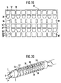
- the heating devices 30 shown are tubular.
- the thread 7 will first guided and passed through an input thread guide 8 then on the circumference of the pipe.
- the thread is with axial and with circumferential components by a thread guide 9 on the output side passed over the pipe.
- the thread guide 9 is one around Pipe axis rotatable disc with a thread guide notch 16.
- Fig. 16 and Fig. 18 is simplified an aligned position of the input thread guide 8 and the notch 16 shown. 17 shows - applicable also to the embodiment 18 - that the disc 9th is twisted so that the thread - as I said - with axial but also with peripheral components is guided over the pipe and thereby describes a steep helix.
- By adjusting the disc 9 can wrap the thread on the tube in the circumferential direction can be set.
- the wrap is synonymous with one Curvature of the thread. Through the wrapping, therefore entire line of the thread on the tube or on the tube attached thread carriers can be reached. On this thread carrier will discussed below.
- the heater consists of three sections, namely Input section 11, control section 13 and end section 12.
- the thread is passed through the input thread guide via the input section 11 8 and the first thread carrier 31.1 of the control range 13 guided.
- the heating surface facing the thread i. H. the jacket of the input section 11 a distance from the thread, which is a multiple of the distance that the thread from the Heating surface, d. H. the lying between the thread carriers 31 Shell areas of the control section.
- the distance of the thread carrier 8 of the first thread carrier 31.1 of the control range also a multiple of the distance between the thread carriers in the control range. Lengths of up to 500 mm can be accepted here become. The length is strongly dependent on the tendency to vibrate.
- the length of the input section 11 is preferably reduced chosen, so that an efficient preheating of the thread is possible.
- the heater is replaced by a resistance heater in the form of a Heating tube 1 heated.
- a resistance heater in the form of a Heating tube 1 heated.
- 6a are the electrical leads of the Resistance heater called.
- the resistance heater is as a heating cartridge 1 runs and extends the entire length of the Heating device, ie via the input section 11, the control section 13 and the end section 12.
- the temperature control of the heating device includes a temperature sensor, which detects the effective actual temperature of the control range 13. This temperature is regulated. Hence the control range a very precise temperature control.
- a plurality of thread carriers 31 are in the control region 13 arranged. All of these thread carriers 31, including the first Thread carrier 31.1 are designed as webs that extend over the circumference of the rule section. These bars have a specific given distance and a certain height above the rest Sheath area of the control area 13. The number of thread carriers will determined by the tendency of the thread to vibrate and the heat transfer.
- the height of the webs compared to the jacket of the control area is preferably chosen to be small and is a maximum of 3 mm. It is preferably in particular less than 1.5 mm.
- the thread is guided over the outer circumference of the thread carrier.
- the thread touches the outer circumference on a certain one Length. This length is also decisive for the heat transfer.
- this contact length is chosen to be short, whereby a compromise with the requirements of heat transfer is required is.
- the axial distance between the thread carriers also has an influence on heat transfer.
- a ratio of touch length to be used for thread carrier spacing of up to approximately 1 to 5, however, this ratio is preferably smaller, in particular smaller than 1 in 10.
- the distance from the heating surface i.e. H. the cloak of the entrance area, is 3 to 10 times the height of the webs 31 compared the shell of the control range, but is preferably smaller than 10 times.
- the representations of the drawing are not true to scale.
- the thread is in turn by only a few Thread carrier guided, namely here by the end thread carrier 31.3 of Control range and the disc 9 already mentioned with its Thread guide notch 16.
- the distance between the thread path and the jacket of the end section 12 is in turn many times larger than the height of the thread guide webs 31 relative to the jacket of the Control range, here the same dimensioning rules as apply to the entrance area 11. Overall, the distance is however, the thread carrier in the end section is smaller than in the entrance section.
- the thread carrier distance is 300 mm and is preferred smaller.
- the heater shown in practice is enclosed in an insulating cage that has a radial slot for thread insertion and compared to the control range of Pipe forms a circumferential gap. In this circumferential gap the Thread led. It is also possible to arrange one at a time Pair of input thread guides 8 and thread guide notches 16 in the Washer 9 to heat two threads on a heater.
- the input thread guide 8 has as far as possible no contact with the Heating device. This ensures that the thread carrier 8 itself not heating up. Therefore, the thread carrier 8 does not form Deposits that arise when the thread is heated.
- the exit thread guide the input section 11 is - as already mentioned - as the first thread carrier 31.1 of the control section 13 is executed. As in the other thread carriers 31.1, 31.2, 31.3 of the control section as mentioned, these are webs. These bridges are from the Sheath of the control area worked out. So you have good thermally conductive contact with the heating device. Because of their low Height ensures that the control temperature is also in the contact surfaces prevails.
- the thread carrier on the output side i.e. H. Disc 9 with thread guide notch 16 is rotatably arranged on the cartridge 1 of the heating device. This ensures that the temperatures of the heating cartridge 1 also communicate the disc 9, so that here too with good Self-cleaning properties can be expected.
- FIG. 18 has a special feature in the circumferential design of the webs serving as thread carriers 31.1, 31.2. and possibly 31.3.
- the webs have a circumferential direction an increasing axial extension. The closest is Do not - as can be seen from Fig. 18 - place exactly a generatrix but essentially on a line leading to the Overflow line of the thread is essentially parallel. This can Overflow line of the thread can be changed. There must be one here overflow line selected under normal operating conditions become. Then, in Fig. 18, not only is the starting thread guide in Shape of the disc 9 with thread guide notch 16 but also the Thread guide 8 rotatable about the axis of the heating device.
- the thread path can be offset on the circumference of the heating device in an area in which the contact length of the thread guide bars 31 has a desired dimension and in which a desired ratio from contact length to free guide length between the webs consists.
- This can increase heat transfer, but also smoothness of the thread can be influenced.
- one too big Touch length to high thread friction, which protects the thread is undesirable.
- 19 is the blank 32 of a sleeve in the rolled-out state 33, in which recesses 34, 35, 36, 34 ', 35' and 36 '.
- the recesses of a respective one Rows are of the same shape and are at the same distance from each other. Between the recesses are transverse to the Blank connecting webs 37, 38, 39, 37 ', 38' and 39 ', on which is discussed in more detail below.
- the in the longitudinal direction of the Blank 32 connecting webs between the respective Series of recesses are irrelevant to the essence of the invention.
- the blank 32 can be Fig. 19 too formed a hollow cylinder and as such on a heating tube 1 to be pulled.
- the inside diameter of the hollow cylinder corresponds to this the outside diameter of the heating pipe.
- the cylinder, below Sleeve 33 is against axial displacement on the heating tube 1 secured, but can be rotated on this, if necessary the Rotational movement from releasing a known but not shown Lock is dependent.
- the recesses 34 in a parallel to the axis of the heating tube 1 lying row and form webs 37 between them Width.
- the webs 37 serve as overflow webs for a thread 7 (the unlike shown here for the sake of simplicity helical around the Cylinder runs) and are of equal width.
- Row of recesses 35 shown here trapezoidal, between which are wedge-shaped webs 38.
- the cuff 33 a further variant of rows of recesses 36 intended.
- These are recesses that are axial Direction are relatively narrow, but wide connecting webs 39 leave between them as a thread overflow webs a thread 7 a offer a larger heating surface.
- According to the other recesses is also diametrically opposite to these in the case of the recesses 36 Row of recesses 36 'with corresponding webs 39 'provided, which form a second thread overflow path.
- the radial distance between the outer surface of the heating tube 1 and the surface of the webs corresponds to the dimensions listed above, is therefore in the preferred range of 0.5-5 mm, preferably 0.5 - 3 mm.
- the cuff 33 can with sufficient working conditions sufficient Recesses of a different shape.
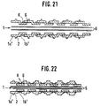
- FIGS. 21 and 22 Further embodiments of the invention are shown in FIGS. 21 and 22 shown. These embodiments have in common that the Thread overflow webs, or rings 2 carrying tubes 1 from sections 1 'are composed.
- the sections exist 1 'each of a part 1'a larger diameter and a part 1'b smaller diameter, the latter the inner diameter of the Part 1'a corresponds to a larger outer diameter.
- the screw connections can be made using lock nuts K are secured, which changes the location of the sections 1 'can be set to each other exactly.
- a thread carrier 2 is provided in each case, which in accordance with of the exemplary embodiments described above can be formed in 21, however, is shown schematically as a simple ring 2.
- the Ring 2 can coaxially enclose part 1'a, but it can also be off-center be arranged. In doing so, he can use his entire scope around a uniform width or gradually or intermittently have increasing widths.
- the outer surface of the ring 2 can be interrupted by at least one axial groove 2 ', with the corresponding Adjustment of rings 2 in addition to the distances between the rings 2 on the tube 1 zones arise from an overflowing thread 7 are not touched.
- this embodiment offers the invention has the advantage that by rotating the pipe sections 1 'depending on the width of the individual rings 2 and their distance to each other, thread contact lengths and contact-free zones in wide Limits are variable.
- the embodiment shown in Fig. 22 differs from that 21 in that instead of the stepped pipe sections 1 ' internal and external sleeves 1 "are provided, which are on the outside - or internal thread G screwed together and if necessary can be secured in position with respect to each other with lock nut K.
- this embodiment also applies to the heating device and their thread carriers taking into account their design the other embodiments said.
- the present invention enables the optimal use of Self-cleaning properties of a heating device at the same time good heating behavior, especially with false twist crimping machines.
Landscapes
- Engineering & Computer Science (AREA)
- Textile Engineering (AREA)
- Yarns And Mechanical Finishing Of Yarns Or Ropes (AREA)
- Thermotherapy And Cooling Therapy Devices (AREA)
Abstract
Description
Die Erfindung betrifft eine Heizeinrichtung, insbesondere einen langgestreckten Körper, wie z. B. ein Heizrohr zur Erhitzung eines laufenden Fadens.The invention relates to a heating device, in particular a elongated body, such as B. a heating tube for heating a running thread.
Eine derartige Heizeinrichtung findet z.B. Anwendung an einer Falschzwirnkräuselmaschine.Such a heater finds e.g. Use on a false twist crimping machine.
Vorrichtungen zum Erhitzen laufender Chemiefäden in Falschzwirnkräuselprozessen sind bekannt. Im allgemeinen weisen sie Schienen auf, die in langgestreckten, auf eine bestimmte Temperatur erwärmbaren Heizkammern liegen, und über die ein Faden über Fadenträger, sog. Stege, geführt werden kann, um erhitzt zu werden.Devices for heating running chemical threads in false twist crimping processes are known. Generally they have rails those in elongated, heatable to a certain temperature Heating chambers are located, and over which a thread over thread carriers, so-called Webs that can be guided to be heated.
Für das Verstrecken und thermische Fixieren synthetischer Fäden sind rohrförmige Fadenüberlaufkörper bekannt. Beispielsweise beschreibt die DE-AS 13 03 384 einen Überlaufkörper, der von dem Faden umschlungen wird. Dieser Überlaufkörper weist eine rotationssymmetrische Form auf und ist am Fadenauflaufende mit einem Wulst versehen und von seinem Fadenauflauf- zu seinem Fadenablaufende hin von der Fadenverstreck- auf die Fadenfixiertemperatur kontinuierlich ansteigend beheizbar und so gestaltet und angeordnet, daß er von dem Faden in Form eines steilen Gewindes umschlungen werden kann. Dieser Fadenüberlaufkörper ist in seinem Aufbau kompliziert und erfordert für seine Herstellung eine Vielzahl von teuren Arbeitsschritten. Zudem dürfte er nicht mit der an moderne Hochgeschwindigkeitsverfahren gestellten Zuverlässigkeit arbeiten.For stretching and thermally fixing synthetic threads tubular thread overflow body known. For example, the DE-AS 13 03 384 an overflow body, which is wrapped by the thread becomes. This overflow body has a rotationally symmetrical Form on and is provided with a bead at the end of the thread and from its thread run-up to its thread run-off end from the Thread stretching - continuously increasing to the thread fixing temperature heatable and designed and arranged so that it from the thread in Form of a steep thread can be wrapped. This thread overflow body is complicated in structure and requires for its manufacturing a multitude of expensive steps. In addition he should not be using the modern high-speed process reliability.
In modernen Falschzwirnkräuselverfahren laufen die Fäden mit erheblicher Geschwindigkeit. Die in den Heizkammern vorherrschenden Temperaturen sind daher entsprechend hoch, was zu Beschädigungen des Fadens führen kann, wenn er mit den Heizoberflächen der Heizeinrichtung in Berührung kommt. Zudem ist es schwierig, eine gleichmäßige Höhe der Fadenbahn über der Heizoberfläche, namentlich in gekrümmten Heizkammern, auf einfache Weise zu schaffen, die gewährleistet, den laufenden Faden schadensfrei zu erwärmen. Darüber hinaus ist es mit den bekannten Heizvorrichtungen nicht möglich, die vorgegebene Krümmung oder Länge einer Fadenlaufbahn ohne großen Aufwand zu verändern.In modern false twist crimping processes, the threads run with considerable Speed. The prevailing in the heating chambers Temperatures are therefore correspondingly high, causing damage of the thread can lead if it with the heating surfaces of the heating device comes into contact. It is also difficult to get an even one Height of the thread path above the heating surface, especially in curved heating chambers, to easily create the ensures that the running thread is heated without damage. About that in addition, it is not possible with the known heaters predefined curvature or length of a thread race without a large one Change effort.
Da derartige Heizeinrichtungen auch Anwendung bei der Be- und Verarbeitung von Folienbändern und Filamenten finden, werden Folienbänder und Filamente stets mitumfaßt, wenn im folgenden von einem Faden gesprochen wird.Since such heating devices also apply to loading and Processing of film strips and filaments can be found Foil tapes and filaments always included if in the following by a thread is spoken.
Als thermoplastisches Material für den Faden kommt insbesondere Polyamid oder Polyethylenterephtalat (PA6, PA6.6) in Betracht, jedoch ohne Einschränkung auf diese Materialien.As a thermoplastic material for the thread comes in particular Polyamide or polyethylene terephthalate (PA6, PA6.6) into consideration, however without limitation to these materials.
Auch aus der EP 0 442 368 A1 ist ein Heizer für ein synthetisches Garn bekannt, dessen Fadenträger oberhalb der Selbstreinigungstemperatur gehalten werden. Bei diesem Heizer wird der Faden in einer Ebene entlang der Heizoberfläche gekrümmt geführt und die Fadenträger werden durch zusätzliche Heizeinrichtungen auf der gewünschten hohen Temperatur gehalten.EP 0 442 368 A1 also describes a heater for a synthetic yarn known, the thread carrier kept above the self-cleaning temperature become. With this heater, the thread is curved in one plane along the heating surface out and the thread carriers are on by additional heating devices maintained the desired high temperature.
Aus der nicht-vorveröffentlichten EP 0 524 111 A1 ist ein rohrförmiger Heizer für einen laufenden Faden bekannt, bei dem zumindest in Teilbereichen der Faden entlang einer im wesentlichen schraubenlinienförmigen Bahn geführt wird. Dabei liegt der Faden in dem schraubenlinienförmig geführten Bereich an einer Heizoberfläche des Heizers an.From the unpublished EP 0 524 111 A1 is a tubular Known heater for a running thread, at least in some areas the thread along a substantially helical path to be led. The thread lies in the helical one Area on a heating surface of the heater.
Aufgabe der Erfindung ist es, eine einfach herzustellende Heizeinrichtung zu schaffen, die bei hohen Temperaturen aller Bauteile betrieben werden kann, und bei der insbesondere die Selbstreinigungseffekte effektiv ausgenutzt werden können. The object of the invention is to provide a heating device which is easy to manufacture and which high temperatures of all components can be operated, and at which in particular uses the self-cleaning effects effectively can.
Diese Aufgabe wird jeweils gelöst durch die Gegenstände der Ansprüche
1 und 2. Durch geeignete Gestaltung und eine wärmetechnisch
enge Anbindung an die eigentliche Heizoberfläche der Heizeinrichtung
können Heizoberfläche und Fadenträger im Betrieb auf einer hohen
Temperatur gehalten werden, insbesondere auf einer Temperatur
oberhalb einer zur Selbstreinigung notwendigen Temperatur gehalten
werden, ohne daß der Faden Schaden nimmt, wobei
die Krümmung der Heizoberfläche und die Steilheit
der Schraubenlinie, in der der Faden geführt wird,
sowie der Abstand zwischen den aufeinander
folgenden Fadenträgern so gewählt werden müssen, daß
der Faden die Heizoberfläche selbst nicht berührt.This object is achieved in each case by the subject matter of the
Es sei folgendes hervorgehoben: Sowohl die Tatsache, daß Fadenträger und die Heizoberfläche besonders guten Wärmekontakt haben, als auch die Tatsache, daß die Stege gegenüber der Heizoberfläche nur eine geringe Höhe haben, vorzugsweise zwischen 0,5 und 3 mm, stellen - jede für sich, wie auch besonders gemeinsam - eine bedeutende Verbesserung gegenüber dem Stand der Technik dar. Diese Verbesserungen sind bei jeder Art von Hochtemperaturheizer, bei dem der Faden in einer gekrümmten Fadenlinie längs einer Heizoberfläche geführt wird, vorteilhaft anwendbar. Ein besonders guter Wärmekontakt kann durch eine einstückige Ausführung von Heizoberfläche und Fadenträgern oder durch mehrere gut wärmeleitend aufgesetzte Fadenträger in Form einer Manschette verwirklicht werden. The following should be emphasized: Both the fact that thread carriers and the heating surface have particularly good thermal contact, as well the fact that the webs are only one against the heating surface have low heights, preferably between 0.5 and 3 mm, each one for itself, as well as special together - a significant improvement over the state of the Technology. These improvements are with every type of high temperature heater, where the thread is in a curved thread line is guided along a heating surface, advantageously applicable. A Particularly good thermal contact can be achieved through a one-piece design of the heating surface and thread carriers or by several good thermal conductors attached thread carriers can be realized in the form of a cuff.
Es ist auch eine zusätzliche Aufgabe der Erfindung, eine Fadenheizvorrichtung zu schaffen, die bei den obigen Eigenschaften zusätzlich eine Beeinflussung des Wärmeüberganges auf einen laufenden Faden für den jeweiligen Anwendungsfall ermöglicht. Das heißt, es soll mit der Erfindung auch eine Fadenheizeinrichtung bereitgestellt werden, die in weiten Grenzen liegende Temperaturprofile entsprechend den erforderlichen Wärmeübetragungsbedingungen ermöglicht. Insbesondere soll mit der Erfindung eine Heizeinrichtung bereitgestellt werden, die Änderungen sowohl in der Krümmung als auch in der Länge der Fadenlaufbahn und in der Fadenüberlauf- bzw. Berührfläche möglich macht.It is also an additional object of the invention to provide a filament heater to create an additional in the above properties Influencing the heat transfer on a running thread for enables the respective application. That means it should be with the Invention also a filament heater can be provided, which in wide temperature profiles corresponding to the required Allows heat transfer conditions. In particular, with The invention provides a heater that changes both in the curvature and in the length of the thread path and makes it possible in the thread overflow or contact surface.
Durch eine relative Bewegung am Eingang und Ausgang der Fadenlaufbahn vorgesehener Fadenführer bzgl. einander kann nicht nur die Länge der Fadenlaufbahn verändert werden, sondern es ist bei entsprechend variabler Breite und/oder Höhe der als Fadenträger wirkenden Längsbereiche auf der Heizoberfläche auch möglich, das Temperaturprofil der auf den Faden einwirkenden Wärmeübertragung steuerbar zu verändern.Through a relative movement at the entrance and exit of the thread track intended thread guide with respect to each other can not only the Length of the thread path can be changed, but it is at accordingly variable width and / or height of those acting as thread carriers Longitudinal areas on the heating surface also possible, the temperature profile the heat transfer acting on the thread controllable change.
Weitere vorteilhafte Ausführungsformen der Erfindung ergeben sich aus den in den abhängigen Ansprüchen beschriebenen Merkmalen.Further advantageous embodiments of the invention result from the features described in the dependent claims.
Durch breitenmäßig veränderbare Fadenüberlaufstege läßt sich die Verweilzeit eines Fadens auf die Heizfläche variieren. Das heißt, indem die beheizte Fläche, auf der der Faden anliegt, in ihrer Größe verändert wird, verändert sich auch die auf den Faden übertragene Wärme. Hinzu kommt, daß durch entsprechende Veränderung der zwischen den Stegen gelegenen berührungsfreien Zonen auch das Profil der Wärmeübertragung regelbar ist. Eine weitere Variationsmöglichkeit ist gegeben durch in ihrer Höhe veränderliche Stege, die es erlauben, den Abstand zwischen der Heizfläche an sich und der Fadenlaufbahn einheitlich oder variabel einzustellen.By changing the width of the thread overflow webs Vary the dwell time of a thread on the heating surface. This means, by the size of the heated surface on which the thread lies is changed, the one transferred to the thread also changes Warmth. In addition, by changing the the non-contact zones between the webs the heat transfer is adjustable. Another possible variation is given by webs that are variable in height, which allow the distance between the heating surface itself and the thread track set uniformly or variably.
Die Fadenüberlauflängen können dadurch verändert werden, daß in Fadenlaufrichtung unmittelbar vor und hinter dem Heizkörper Fadenführer vorgesehen werden, die in ihrer Lage relativ zu dem Heizkörper und/oder zueinander verstellbar sind. Gegebenenfalls können diese Fadenführer aber auch am Ein- und Ausgang des Heizkörpers selbst vorgesehen sein. The thread overflow lengths can be changed in that Thread running direction immediately in front of and behind the heating element be provided in their position relative to the radiator and / or are mutually adjustable. If necessary, these Thread guide but also at the entrance and exit of the radiator itself be provided.
Im übrigen wird bezüglich beispielhafter Formen der Fadenträger auf die Beschreibung verwiesen.Incidentally, regarding exemplary shapes the thread carrier referred to the description.
Insbesondere soll darauf hingewiesen werden, daß die erfindungsgemäße Heizeinrichtung in einem Temperaturbereich gefahren werden kann, welcher der Selbstreinigungstemperatur der beheizten Oberfläche entspricht.In particular, it should be noted that the invention Heating device can be operated in a temperature range, which is the self-cleaning temperature of the heated surface corresponds.
Dabei macht sich die Erfindung die Erkenntnis zunutze, daß die Selbstreinigungstemperatur in der Größenordnung von ca. 430 Grad Celsius liegt, und daß über die Beeinflussung des Wärmeübergangs von der beheizten Oberfläche auf den aufzuheizenden Faden der Faden einer geringeren Temperatur von z.B. 330 Grad Celsius ausgesetzt wird.The invention makes use of the knowledge that the Self-cleaning temperature in the order of approximately 430 degrees Celsius lies, and that about the influence of the heat transfer of the heated surface on the thread to be heated the thread a lower temperature e.g. Exposed to 330 degrees Celsius becomes.
Diese Maßnahmen sind insbesondere dann von Vorteil, wenn thermoplastische Fäden mit geringen Titern von z.B. 20 Den. und beispielsweise einer Fadengeschwindigkeit von ca. 1000 Meter pro Minute die erfindungsgemäße Heizeinrichtung durchlaufen.These measures are particularly advantageous when thermoplastic Threads with low titers of e.g. 20 den. and for example a thread speed of approx. 1000 meters per minute pass through the heating device according to the invention.
Durch diese Maßnahmen läßt sich praktisch selbsttätig verhindern, daß die beheizte Oberfläche durch fortlaufende Ablagerungen vom vorbeilaufenden Faden allmählich zuwächst, so daß die Aufheizbedingungen für den laufenden Faden über die gesamte Fadenlänge im wesentlichen konstant gehalten werden können.These measures can practically automatically prevent that the heated surface through continuous deposits from the passing Thread gradually grows so that the heating conditions for the running thread over the entire length of the thread essentially can be kept constant.
Insbesondere bietet sich diese Möglichkeit an, wenn eine Heizeinrichtung für mehrere aufzuheizende Fäden vorgesehen ist. In diesem Falle kann während der Reinigungsphase einer der Fadenheizzonen der andere Faden in seiner zugehörigen Fadenheizzone kontinuierlich weiterlaufen, ohne daß die Selbstreinigung der ersten Fadenheizzone eine Auswirkung auf die Qualität des weiterhin laufenden Fadens in der zweiten Fadenheizzone haben könnte.This option is particularly useful if a heating device is provided for several threads to be heated. In this Trap can one of the thread heating zones during the cleaning phase other thread in its associated thread heating zone continuously continue to run without the self-cleaning of the first thread heating zone an impact on the quality of the thread still running in the second thread heating zone.
Auch kann es sinnvoll sein, die Fadenheizzonen in bestimmten Zeitabständen unter dem laufenden Faden vorbei zu drehen bzw. zu bewegen, um zu einer regelmäßigen Selbstreinigung der Fadenheizzonen zu gelangen.It may also be useful to set the thread heating zones at certain intervals to turn under the running thread or to move to regular self-cleaning of the filament heating zones to get.
Im folgenden wird u.a. auf eine spezielle Ausführungsform der Erfindung eingegangen, welche als Heizeinrichtung für eine Falschzwirn-kräuselmaschine Anwendung findet.In the following, to a special embodiment of the invention received, which as a heater for a false twist crimping machine Application.
Diese Heizeinrichtung ist beschrieben in der EP 0 412 429 A2. Der Vorteil dieser Heizeinrichtung liegt zum einen in ihrer hohen Heizleistung, die auf den Faden übertragbar ist und eine kurze Länge des Heizers gestattet. Der andere Vorteil liegt in dem Selbstreinigungseffekt.This heating device is described in EP 0 412 429 A2. Of the One advantage of this heating device is its high heating output, which is transferable to the thread and a short length of Heater allowed. The other advantage is the self-cleaning effect.
Es hat sich herausgestellt, daß dieser Selbstreinigungseffekt über die Länge des Heizers unterschiedlich ist.It has been found that this self-cleaning effect over the Length of the heater is different.
Eine zusätzliche Aufgabe der Erfindung hinsichtlich dieser speziellen Ausführungsform besteht darin, den bekannten Heizer so weiter auszugestalten, daß eine Reinigung des Heizers von angebackenen oder vercrackten Resten des thermoplastischen Fadenmaterials nicht erforderlich wird.An additional object of the invention with regard to this particular Embodiment is to continue the known heater To design that a cleaning of the heater from baked or Cracked residues of the thermoplastic thread material are not required becomes.
In einer besonderen Ausführungsform der Erfindung kann der Heizer einen Eingangsbereich aufweisen, in dem der Faden nur geringen oder keinen Kontakt mit Fadenträgern hat, indem dort die Fadenträger nur mit großem Abstand angeordnet werden. Vorzugsweise wird der Eingangsbereich nur mit einem Eingangsfadenführer und der Ausgangsbereich nur mit einem Ausgangsfadenführer ausgestattet. Darüber hinaus erweist es sich als vorteilhaft, daß der Eingangsfadenführer kalt bleibt. Es wird aus diesem Grunde vorgeschlagen, daß der Eingangsfadenführer keinen Wärmekontakt mit der Heizoberfläche hat. Dadurch bleibt der Fadenführer im wesentlichen kalt, so daß es nicht zu Absonderungen von thermoplastischem Material kommen kann. Der ausgangsseitige Fadenführer soll dagegen Selbstreinigungseigenschaft haben. Er wird daher vorzugsweise unmittelbar mit der Heizoberfläche verbunden und liegt am Beginn des sogenannten "Regelabschnittes", der sich an den Eingangsbereich anschließt.In a particular embodiment of the invention, the heater have an entrance area in which the thread is only slight or has no contact with thread carriers by only holding the thread carriers there be arranged at a large distance. Preferably the Entrance area only with an entrance thread guide and the exit area only equipped with a starting thread guide. About that it also proves advantageous that the input thread guide is cold remains. For this reason, it is suggested that the input thread guide has no thermal contact with the heating surface. This keeps the thread guide essentially cold so that it does not secretions of thermoplastic material can occur. Of the the thread guide on the output side, on the other hand, is said to be self-cleaning to have. It is therefore preferably directly with the heating surface connected and lies at the beginning of the so-called "rule section", the adjoins the entrance area.
Der Regelabschnitt ist der Abschnitt, in dem der Faden seine Solltemperatur erhält. In dem Regelabschnitt sind mehrere Fadenträger angeordnet. Diese Fadenträger haben voneinander gleiche oder - wie durch die oben genannte EP 0 412 429 A2 dargestellt - variable Abstände.The control section is the section in which the thread reaches its set temperature receives. There are several thread carriers in the control section arranged. These thread carriers have the same or - from each other represented by the above-mentioned EP 0 412 429 A2 - variable Distances.
Durch die Verwendung der Fadenträger im Regelabschnitt wird sichergestellt, daß der Faden mit genau definierbarem Abstand von der Heizoberfläche geführt wird. Um darüber hinaus zu gewährleisten, daß der Faden im Eingangsabschnitt nicht in Kontakt mit der Heizoberfläche gerät, wird weiterhin vorgeschlagen, daß die Heizeinrichtung zwischen Eingangsabschnitt und Regelabschnitt eine Abstufung erhält, derart, daß der Abstand der Heizoberfläche im Eingangsabschnitt von dem Fadenlauf größer ist, vorzugsweise ein Vielfaches desjenigen Abstandes beträgt, den der Fadenlauf im Regelabschnitt von der Heizoberfläche hat. By using the thread carrier in the control section ensures that the thread with a precisely definable distance from the Heating surface is performed. In addition, to ensure that the thread in the entrance section is not in contact with the heating surface device, it is further proposed that the heating device receives a gradation between the input section and the control section, such that the distance of the heating surface in the entrance section of the thread path is larger, preferably a multiple of that Distance is that the thread path in the control section of the Heating surface.
Es ist weiterhin zur Verbesserung der Selbstreinigungseigenschaften vorgesehen, daß die Stege und die Heizoberfläche aus einem Stück gefertigt sind, d. h., daß die Heizoberfläche aus Stegen und damit abwechselnden Vertiefungen besteht. Jede dieser Maßnahmen ist dazu geeignet und bestimmt zu gewährleisten, daß die Stege auf dieselbe hohe Temperatur wie die Heizoberfläche aufgeheizt werden, d. h. auf Temperaturen, die höher sind als 300° C bis 350° C.It continues to improve self-cleaning properties provided that the webs and the heating surface from one Pieces are manufactured, d. that is, the heating surface from webs and so that there are alternating wells. Each of these measures is suitable and determined to ensure that the webs on the same high temperature as the heating surface is heated, d. H. to temperatures higher than 300 ° C to 350 ° C.
Durch die erfindungsgemäße Anordnung der Fadenträger wird gewährleistet, daß die Fadenträger nur in der Zone angeordnet sind, in der die erreichte Temperatur des Fadens einerseits sowie die Heizertemperatur andererseits die Selbstreinigung sicherstellen. In der Regelzone erfolgt eine genaue Temperaturführung der Heizeinrichtung, und zwar vorzugsweise durch Regelung. Durch die präzise Führung des Fadens, relativ zu der Heizeinrichtung, wird hier gewährleistet, daß der Faden die vorgegebene Solltemperatur annimmt. Dabei kann durch variable Breiten der Fadenträger bezüglich eines laufenden Fadens bei beweglichen Fadenträgern die sog. Verweilzeit des Fadens in weiten Grenzen veränderbar gehalten werden, d. h. die Berührfläche zwischen Faden und Fadenträger wird in Abhängigkeit von am Faden oder am Heizkörper gemessenen Temperaturen eingestellt. Im Eingangsabschnitt wird auf die genaue Führung des Fadens verzichtet. Dabei wird von der Erkenntnis Gebrauch gemacht, daß im Eingangsabschnitt die Aufheizung des Fadens mit großen Temperaturgradienten zwischen Heizeinrichtung und Faden erfolgt und daher eine genaue Temperaturführung des Fadens weder gewollt noch möglich ist.The arrangement of the thread carriers according to the invention ensures that that the thread carriers are only arranged in the zone in which the temperature of the thread reached on the one hand and the heater temperature on the other hand, ensure self-cleaning. In the control area there is an exact temperature control of the heating device, namely preferably by regulation. Due to the precise guidance of the thread, relative to the heater, it ensures that the thread assumes the specified target temperature. It can be variable Widths of the thread carriers with respect to a running thread with movable ones Thread carriers the so-called dwell time of the thread in wide Limits are kept changeable, d. H. the interface between Thread and thread carrier is depending on the thread or on Radiator measured temperatures set. In the entrance section the exact guidance of the thread is dispensed with. Here is from made use of the knowledge that the Heating the thread with large temperature gradients between Heating device and thread takes place and therefore an exact temperature control the thread is neither wanted nor possible.
Die Aufheizung des Fadens im Regelbereich bewirkt, daß zunächst die Außenschichten des Fadens die gewünschte Temperatur annehmen. Erforderlich ist aber eine gleichmäßige Erhitzung des Fadens über seinen gesamten Querschnitt. Dieses Ziel wird dadurch erreicht, daß dem Regelabschnitt ein Endabschnitt nachgeordnet wird, in dem wiederum Fadenträger mit großem Abstand oder aber kein Fadenträger angeordnet ist. Um zu vermeiden, daß der Faden in Kontakt mit der Heizoberfläche der Heizeinrichtung gerät, sollte auch hier vorzugsweise der Abstand zwischen Fadenlauf und Heizoberfläche größer, vorzugsweise ein Vielfaches des Abstandes sein, welchen Fadenlauf und Heizoberfläche im Regelbereich haben. Durch diese Anordnung des Endabschnittes wird sichergestellt, daß bei nur geringer Wärmeübertragung Wärmeverluste verhindert werden und eine gleichmäßige Verteilung der im Regelabschnitt zugeführten Wärme über den gesamten Fadenquerschnitt erfolgt.The heating of the thread in the control area causes the The outer layers of the thread assume the desired temperature. However, uniform heating of the thread is required its entire cross section. This goal is achieved in that the control section is followed by an end section in which again thread carrier with a large distance or no thread carrier is arranged. To avoid the thread in contact with the Heating surface of the heating device should also be preferred here the distance between the thread path and the heating surface is larger, preferably be a multiple of the distance, which thread run and Have a heating surface in the control range. By this arrangement of the End section ensures that with little heat transfer Heat loss can be prevented and an even distribution the heat supplied in the control section over the entire Thread cross-section takes place.
Im Eingangsabschnitt kann eine große, ungestützte Fadenlänge in Kauf genommen werden; es hat sich nämlich herausgestellt, daß im Eingangsabschnitt die Neigung des Fadens zur Schwingung gering ist. Eine Länge von 400 mm - 500 mm ist möglich. Die Länge sollte jedoch zur Begrenzung des Aufwandes auf das Maß verlängert werden, was zur Erzielung der gewünschten Vorheizung des Fadens erforderlich ist.A large, unsupported length of thread can be purchased in the entrance section be taken; it turned out that in the entrance section the tendency of the thread to oscillate is low. A Length of 400 mm - 500 mm is possible. The length should, however Limitation of the effort to be extended to what Achieving the desired preheating of the thread is necessary.
Der Endabschnitt ist jedenfalls kürzer als der Eingangsabschnitt. Die Länge des Endabschnittes ist vorzugsweise begrenzt auf 300 mm und sollte insbesondere noch kürzer sein.The end section is in any case shorter than the entrance section. The The length of the end section is preferably limited to 300 mm and should be even shorter in particular.
Der Abstand zwischen Fadenlauf und Heizoberfläche im Endabschnitt und im Eingangsabschnitt ist größer, vorzugsweise ein Vielfaches des Abstandes im Regelbereich, jedoch vorzugsweise auch begrenzt auf 5 mm, vorzugsweise 3 mm. The distance between the thread run and the heating surface in the end section and in the entrance section is larger, preferably a multiple of that Distance in the control range, but preferably also limited to 5 mm, preferably 3 mm.
Von der Tatsache, daß die Berührlänge der Fadenträger Einfluß auf die Wärmeübertragung hat, kann im Rahmen dieser Erfindung besonders vorteilhaft Gebrauch gemacht werden.From the fact that the touch length affects the thread carrier which has heat transfer can be particularly within the scope of this invention be used advantageously.
Die Optimierung der Heizeinwirkung auf den Faden ist von großer Bedeutung für die Qualität des Fadens und seine Texturierung in der Falschzwirnkräuselmaschine. Aus diesem Grunde wird vorgeschlagen, daß die Berührlänge der Fadenträger einstellbar ist. Hierdurch kann außerdem eine optimale Einstellung der Heizeinwirkung auf die jeweils gewünschte Fadenlaufgeschwindigkeit und den Fadendurchmesser (Titer) erfolgen.The optimization of the heating effect on the thread is of great importance Significance for the quality of the thread and its texturing in the False twist crimping machine. For this reason it is proposed that the touch length of the thread carrier is adjustable. This can also an optimal setting of the heating effect on each desired thread speed and thread diameter (titer) respectively.
Zur Optimierung der Heizeinwirkung und zur Anpassung an Fadenlaufgeschwindigkeit und Titer wird fernerhin als vorteilhaft vorgeschlagen, das Verhältnis der Berührlänge der Fadenführung zu der kontaktfreien Länge der Heizeinrichtung einstellbar zu gestalten, insbesondere im Bereich der Regelzone. Eine Heizeinrichtung kann z. B. die Form eines Rohres haben, auf dessen Umfang mehrere sich in Umfangsrichtung in ihrer axialen Ausdehnung verbreiternde Stege vorgesehen sind. Diese Stege können nacheinander versetzt auf dem Umfang angeordnet sein. Dadurch wird erreicht, daß der das Rohr schraubenartig umschlingende Faden nacheinander die Stege in Bereichen berührt, in denen die Stege im wesentlichen gleiche Berührlänge haben.To optimize the effect of heating and to adapt to the thread speed and titer is also proposed as advantageous the ratio of the contact length of the thread guide to the non-contact To make the length of the heater adjustable, in particular in the area of the control area. A heater can e.g. B. the shape have a pipe, on the circumference of which there are several in the circumferential direction in their axial extension widening webs are provided. These webs can be successively arranged offset on the circumference be. It is thereby achieved that the screw-wrapping around the tube Thread touches the webs one after the other in areas which the webs have essentially the same contact length.
Eine weitere Ausführungsform, die jederzeit eine Anpassung der Heizwirkung an die spezifischen Prozeßparameter, insbesondere Fadentiter und Laufgeschwindigkeit gestattet, besteht aus einem durch zusammengesetzte Abschnitte in seiner Länge veränderbaren Heizkörper. Another embodiment that can be adjusted at any time Heating effect on the specific process parameters, especially thread titer and running speed allowed consists of a through Composed sections of radiators variable in length.
Gemäß einer weiteren Ausführungsform der Erfindung besteht die Möglichkeit auf ein im wesentlichen mit glatter Oberfläche versehenes Heizrohr eine Manschette bzw. einen Käfig zu stülpen, dessen Innendurchmesser dem Außendurchmesser des Heizrohres entspricht und dessen Mantel durch zeilenmäßig aneinandergereihte Ausnehmungen gleicher Form durchdrungen ist. Vorzugsweise liegen sich in der Manschette Zeilen gleichförmiger Ausnehmungen diametral gegenüber, wobei vorzugsweise neben diesen Zeilen aneinandergereihter Ausnehmungen Zeilen mit Ausnehmungen anderer Formen liegen. Vorzugsweise verlaufen die Zeilen achsparallel. Zwischen den aneinandergereihten Ausnehmungen liegen der Form der Ausnehmungen entsprechende gleichförmige sich umfangsmäßig erstreckende Stege. Die Manschette ist auf dem Heizrohr gegen axiale Verlagerung gesichert, kann aber gedreht werden. Daraus ergibt sich zum einen der Vorteil, daß durch allmähliches Drehen der Manschette auf dem Rohr der Faden stets über eine saubere Überlaufstelle der Stege geführt werden kann; zum anderen kann der Faden durch die unterschiedliche Gestaltung der Stege in weiten Temperaturbereichen beheizt werden. Da sich in der Manschette gleichförmige Stege bzw. Ausnehmungen diametral gegenüberliegen bzw. in bestimmten Winkelabständen wiederholen, werden Überlaufbahnen für zwei oder mehr Fäden gebildet. Im übrigen sind die zwischen den Zeilen in Längsrichtung der Manschette verlaufenden Stege für das Wesen der Erfindung ohne Bedeutung.According to a further embodiment of the invention, the Possibility of an essentially smooth surface Heating tube to put a sleeve or a cage, the inside diameter corresponds to the outside diameter of the heating pipe and its mantle through recesses lined up in rows same shape is permeated. Preferably lie in the Cuff lines of uniform recesses diametrically opposite, preferably next to these lines of recesses lined up Lines with recesses of other shapes lie. Preferably the lines run parallel to the axis. Between the strings Recesses correspond to the shape of the recesses uniform circumferentially extending webs. The cuff is secured on the heating pipe against axial displacement, can but be rotated. On the one hand, this has the advantage that by gradually turning the cuff on the tube of thread can always be run over a clean overflow point of the webs; on the other hand, the thread through the different design the webs are heated in wide temperature ranges. Because in the cuff has uniform webs or recesses diametrically opposite or repeating at certain angular intervals, overflow paths for two or more threads are formed. in the the rest are those between the rows in the longitudinal direction of the cuff extending webs of no importance for the essence of the invention.
Ausführungsbeispiele der Erfindung, auf die diese jedoch nicht beschränkt ist, sind in den Zeichnungen dargestellt und werden nachstehend näher beschrieben.Embodiments of the invention, but not limited to these are shown in the drawings and are described below described in more detail.
Es zeigen:
- Fig. 1
- eine Draufsicht auf eine zum Führen eines Fadens geeignete Scheibe gem. der Erfindung;
- Fig. 2
- einen Schnitt entlang Linie II-II in
Figur 3; - Fig. 3
- eine Seitenansicht der erfindungsgemäßen Heizeinrichtung;
- Fig. 4
- eine Seitenansicht einer weiteren Ausführungsform der Erfindung;
- Fig. 5
- eine Seitenansicht einer dritten Ausführungsform der Erfindung; und
- Fig. 6
- eine vierte Ausführungsform mit verstellbaren Fadenführern der Erfindung in Seitenansicht.
- Fig. 7
- eine Schnittansicht einer Heizeinrichtung mit Ringen, deren Höhe sich in Umfangsrichtung ändert.
- Fig. 8
- eine perspektivische Ansicht einer Heizeinrichtung gem. Fig. 7 mit relativ zueinander verdrehbaren Fadenführern;
- Fig. 9
- eine Draufsicht auf eine Heizeinrichtung mit sich in Umfangsrichtung ändernden Stegbreiten und Steghöhen;
- Fig. 10
- eine axiale Aufsicht auf eine erfindungsgemäße Heizeinrichtung;
- Fig. 11
- ein Anwendungsbeispiel in einer Falschzwirnkräuselmaschine;
- Fig. 12
- ein allgemeines Ausführungsbeispiel der Erfindung mit zwei gleichartigen Fadenheizzonen;
- Fig. 13
- ein weiteres Ausführungsbeispiel der Erfindung mit einer nichtverstellbaren und einer verstellbaren Fadenheizzone;
- Fig. 14
- ein weiteres Ausführungsbeispiel der Erfindung mit zwei unterschiedlich einstellbaren Fadenheizzonen;
- Fig. 15
- axiale Aufsichten auf Heizeinrichtungen mit jeweils zwei Fadenheizzonen und elliptischen Ringen beziehungsweise exzentrischen Ringen;
- Fig. 16
- einen weiteren Längsschnitt;
- Fig. 17
- die Ansicht eines rohrförmigen Heizers;
- Fig. 18
- ein modifiziertes Ausführungsbeispiel eines rohrförmigen Heizers;
- Fig. 19
- eine Draufsicht auf den Rohling einer Fadenüberlaufmanschette in ausgerolltem Zustand mit drei Paaren voneinander unterschiedlichen Fadenüberlaufstegen;
- Fig. 20
- eine perspektivische Ansicht, in verkleinertem Maßstab, eines Heizrohres mit darauf gestülpter Manschette;
- Fig. 21
- einen Längsschnitt durch ein aus mehreren zueinander verstellbaren Abschnitten bestehendes Heizrohr; und
- Fig. 22
- einen Längsschnitt durch ein anderes aus Abschnitten bestehendes Heizrohr.
- Fig. 1
- a plan view of a suitable for guiding a thread according to. the invention;
- Fig. 2
- a section along line II-II in Figure 3;
- Fig. 3
- a side view of the heating device according to the invention;
- Fig. 4
- a side view of another embodiment of the invention;
- Fig. 5
- a side view of a third embodiment of the invention; and
- Fig. 6
- a fourth embodiment with adjustable thread guides of the invention in side view.
- Fig. 7
- a sectional view of a heater with rings, the height changes in the circumferential direction.
- Fig. 8
- a perspective view of a heater acc. 7 with thread guides which can be rotated relative to one another;
- Fig. 9
- a plan view of a heating device with web widths and web heights changing in the circumferential direction;
- Fig. 10
- an axial view of a heating device according to the invention;
- Fig. 11
- an application example in a false twist crimping machine;
- Fig. 12
- a general embodiment of the invention with two similar filament heating zones;
- Fig. 13
- a further embodiment of the invention with a non-adjustable and an adjustable thread heating zone;
- Fig. 14
- a further embodiment of the invention with two differently adjustable filament heating zones;
- Fig. 15
- axial plan views of heating devices, each with two filament heating zones and elliptical rings or eccentric rings;
- Fig. 16
- another longitudinal section;
- Fig. 17
- the view of a tubular heater;
- Fig. 18
- a modified embodiment of a tubular heater;
- Fig. 19
- a plan view of the blank of a thread overflow sleeve in the rolled-out state with three pairs of different thread overflow webs;
- Fig. 20
- a perspective view, on a smaller scale, of a heating tube with a sleeve placed thereon;
- Fig. 21
- a longitudinal section through a heating tube consisting of several mutually adjustable sections; and
- Fig. 22
- a longitudinal section through another heating pipe consisting of sections.
In der nachfolgenden Beschreibung der verschiedenen Ausführungsformen der Erfindung werden für gleiche Teile gleiche Bezugszeichen verwendet.In the following description of the various embodiments the same reference numerals for the same parts of the invention used.
Die in Figur 3 gezeigte Heizvorrichtung weist ein Rohr 1, im folgenden
Heizrohr, auf. Das Heizrohr 1 trägt in seinem Inneren zwei
parallel zueinander verlaufende Heizwiderstände 6, die vorzugsweise
von einander und von der inneren Mantelfläche des Heizrohres 1 von
einem geeigneten Isoliermaterial wie beispielsweise Magnesiumoxyd-
oder Magnesiumsilikatpulver getrennt sind. Das Heizrohr 1 besteht aus
einem gut wärmeleitenden Metall, wie Stahl oder vorzugsweise aus
einer Kupfer-Aluminium-Legierung.The heating device shown in Figure 3 has a
Die in den Figuren 1 und 2 im einzelnen dargestellten Scheiben
2 sind kreisförmig und mit einem radialen Schlitz 5 versehen, dessen
lichte Weite im wesentlichen dem Durchmesser des Heizrohres 1
entspricht und dessen gegenüberliegende Kanten parallel zueinander
liegen. Der äußere Rand der Scheiben 2 ist ballig ausgebildet. In der
einen Stirnfläche der Scheiben befindet sich eine Mehrzahl von
Vertiefungen oder Ausnehmungen 4, die in gleichem Abstand zueinander
und von der Achse der Scheibe 2 liegen. Von der gegenüberliegenden
Stirnseite der Scheibe 2 steht ein als Abstandhalter dienender
Stift 3 vor, dessen Abstand von der Achse der Scheibe dem
Abstand der Ausnehmungen 4 von der Scheibenachse entspricht.The disks shown in Figures 1 and 2 in
Die balligen Ränder der Scheiben 2 dienen zur Führung eines Fadens
7, der über einen Eingangsfadenführer 8 an die von den balligen
Kanten der Scheiben 2 gebildete Fadenüberlauffläche der Heizvorrichtung
gelegt wird und diese über einen zum Fadenträger 8 winklig
und achsial versetzten Ausgangsfadenführer 9 verläßt. Das heißt, der
Faden 7 umschlingt die Vorrichtung in einem Wendel, dessen Steigung
abhängig ist von dem Versatz der Fadenträger 8 und 9 zu einander.
Wenigstens einer der Fadenträger ist relativ zum anderen um die
Achse des Heizrohres 1 verschwenkbar, so daß sich die Länge der
Fadenlaufbahn über die Scheiben 2 durch Änderung der Steigung des
von dem Faden 7 gebildete Wendel verändern läßt. Die Stellungen der
Fadenträger 8 und 9 liegen zu beiden Seiten der Schlitze 5 und der
Wendel des Fadens 7 liegt in dem außerhalb der Schlitze 5 gelegenen
Bereich der Scheiben 2.The spherical edges of the
Vorzugsweise bestehen die Scheiben aus einem wärme- und zunderbeständigen Material, z. B. Aluminiumoxyd oder Titanoxyd. Um die Abriebfestigkeit der Scheibenkanten zu erhöhen, können diese ggf. mit einem geeigneten Metall beschichtet sein und um ihre Fadenfreundlichkeit zu erhöhen, können die Scheibenkanten geschliffen oder poliert sein.Preferably, the disks are made of a heat and scale resistant Material, e.g. B. aluminum oxide or titanium oxide. To the To increase the abrasion resistance of the window edges, you can use these if necessary be coated with a suitable metal and its thread friendliness to increase, the edge of the pane can be ground or polished be.
Die in Fig. 4 gezeigte Ausführungsform der Erfindung besteht aus
einem mit einem elektrischen Heizwiderstandsdraht 6 versehenen
Heizrohr 1, welches von einer Vielzahl von Ringen 2 umgeben ist. Die
Ringe 2 sind beispielsweise durch Verlötung fest mit dem Heizrohr 1
verbunden und liegen in gleichem Abstand voneinander. Die Ringe 2
können aber auch von Wülsten gebildet werden, die in regelmäßigen
Abständen in das Rohr gestaucht werden. Die Ringe können auch
durch Nuten voneinander beabstandet sein, die in den Außenmantel
des Heizrohrs 1 eingearbeitet sind. Die radial vorstehende Umfangsfläche
der Ringe 2 ist ballig gestaltet und ist von fadenfreundlicher
Beschaffenheit. Die Ringe 2 dienen dazu, einen Faden 7 im Abstand
über die Mantelfläche des beheizten Rohres 1 zu führen, wobei die
Fadenüberlaufbahn sich vorzugsweise wendelförmig um das Rohr 1
schlingt. Wie schematisch dargestellt, befinden sich zu beiden Enden
des Heizrohres 1 Fadenführer 8 und 9, deren Versatz bzgl. einander
Steigung und Länge der Fadenlaufbahn bestimmen. Wenigstens einer
der beiden Fadenführer kann bezüglich des anderen verstellt werden.
Die zum Verstellen dieses Fadenführers erforderlichen Mittel gehören
zum Stand der Technik und sind nicht dargestellt.The embodiment of the invention shown in Fig. 4 consists of
one provided with an electrical
Die in Fig. 5 gezeigte Ausführungsform der Erfindung besteht aus
einem Heizrohr 1, das in seinem Innern einen elektrischen Widerstandsheizdraht
6 aufweist und das über seine gesamte Länge von
einem schraubenförmigen Fadenträger 2 umgeben ist. Der schraubenförmige
Fadenträger 2 ist z. B. durch Verlötung fest mit dem Rohr
1 verbunden. Seine nach außen weisende Fläche ist ballig und von
fadenfreundlicher Beschaffenheit, d. h., sie übt auf einen überlaufenden
Faden eine möglichst vernachlässigbare Reibung aus. Der Faden 7 wird
hier in einem Wendel geführt, der den Gängen des Fadenträgers 2
entgegengesetzt ist. Der Faden wird mittels ösenförmiger Fadenführer 8
und 9, die am Auflauf- und Ablaufende des Heizrohres 1 vorgesehen
sind, an den schraubenförmigen Fadenträger 2 gelegt. Wie bei den
bereits beschriebenen Ausführungsbeispielen ist es möglich, die Fadenführer
8,9 relativ zueinander zu verstellen.The embodiment of the invention shown in Fig. 5 consists of
a
Eine vierte Ausführungsform der Erfindung ist in Fig. 6 dargestellt.
Auch hier handelt es sich um ein von einem Heizwiderstand 6 beheiztes
Rohr 1. In diesem Falle ist das Rohr 1 von einem schraubenförmigen
Fadenträger 2 umschlungen, der aus einem biegsamen, möglichst
elastischen Material besteht. Der Fadenträger 2 kann beispielsweise ein
Metallröhrchen sein, dessen gegen das Heizrohr 1 liegende Fläche
abgeflacht ist, so daß ein enger Wärmekontakt zwischen dem Heizrohr
1 und dem Fadenträger 2 besteht. A fourth embodiment of the invention is shown in FIG. 6.
This is also a
Indem die am Auflauf- und Ablaufende des Heizrohres vorgesehenen Fadenführer 8, 9 verstellt werden können, läßt sich die Steigerung der Fadenüberlaufbahn verändern.By the end of the run-up and run-down of the heating tube provided thread guides 8, 9 are adjusted can, the increase in the thread overtravel change.
Die hier beschriebenen Fadenüberlaufheizvorrichtungen bieten u. a. die Vorteile, in weiten Grenzen variierbare Fadenüberlaufbahnen zu ermöglichen. Des weiteren lassen sich durch Hintereinanderhalten mehrerer unterschiedlich beheizter Fadenträger über die Länge einer Fadenlaufbahn variable Temperaturprofile verwirklichen.The thread overflow heaters described here offer u. a. the Advantages of variable thread overflow paths within wide limits enable. Furthermore, can be held in a row several differently heated thread carriers over the length of one Thread path realize variable temperature profiles.
Weiterhin zeigen die Figuren 7 - 9 und 11 - 15 Heizeinrichtungen, bei
denen am Fadeneingang und am Fadenausgang des Heizrohres 1 ein
Eingangsfadenführer 8 und ein Ausgangsfadenführer 9 sitzen, und bei
der die Fadenträger 8, 9 und das Rohr 1 in Umfangsrichtung des
Rohres relativ zueinander verdrehbar sind.Furthermore, FIGS. 7-9 and 11-15 show heating devices
those at the thread inlet and at the thread outlet of the
Dies kann entweder durch drehbar angeordnete Eingangs- und/oder
Ausgangsfadenführer 8,9 im Zusammenwirken mit einem ortsfesten
Heizrohr 1 erreicht werden oder mit ortsfest angeordneten Eingangs-
und/oder Ausgangsfadenführern 8,9 zusammen mit einem um seine
Längsachse drehbaren Heizrohr 1 oder mit drehbaren Eingangs-
und/oder Ausgangsfadenführern 8,9 im Zusammenwirken mit einem
drehbaren Heizrohr 1.This can be done either by rotatably arranged input and / or
Starting thread guide 8.9 in cooperation with a
Im Ausführungsbeispiel nach Figur 7 ist lediglich der Ausgangsfadenführer
9 relativ zum Rohr drehbar, während der Eingangsfadenführer
8 ortsfest sitzt.In the exemplary embodiment according to FIG. 7, only the starting thread guide is
9 rotatable relative to the tube while the
Im Ausführungsbeispiel nach Figur 7 sitzt der Ausgangsfadenführer 9,
gebildet durch die Kerbe 16, koaxial und drehbar auf dem unteren
Ende des Heizrohres 1 und ist in dem Drehbereich 15 relativ zum
Rohr verdrehbar.In the exemplary embodiment according to FIG. 7, the starting
Es ist ersichtlich, daß bei einer Verdrehung des Ausgangsfadenführers
9 relativ zum Rohr der laufende Faden 7 eine Wendel auf den
Ringen 2 beschreibt, deren Geometrie (Windung, Steigung) von der
Drehstellung der Kerbe 16 am Ausgangsfadenführer 9 abhängig ist.It can be seen that when the starting thread guide is twisted
9 relative to the tube of the running thread 7 a coil on the
Es soll der Vollständigkeit halber gesagt sein, daß das Heizrohr 1 eine
elektrische Widerstandsheizung besitzt, die über die elektrischen
Zuleitungen 6a mit dem Heizstrom versorgt wird.For the sake of completeness, it should be said that the
Weiterhin zeigen Figur 7 - 9 und 11 - 14 daß die Heizeinrichtungen
am Eingang des Heizrohres 1 und/oder am Ausgang des Heizrohres 1
jeweils einen Eingangsabschnitt 11 bzw. Endabschnitt 12 aufweisen
können, der zum vorbeilaufenden Faden 7 einen größeren Radialabstand
als die Mantelfläche des Heizrohres 1 einnimmt.Furthermore, Figures 7-9 and 11-14 show that the heating devices
at the entrance of the
Zwischen dem Eingangsabschnitt 11 und dem Endabschnitt 12 sitzt der
Regelabschnitt 13, der im vorliegenden Fall eine weitere Besonderheit
aufweist.Between the
Wie hierzu u.a. aus Figur 9 erkennbar ist, sind der Eingangsfadenführer
8 und der Ausgangsfadenführer 9 relativ zum Heizrohr 1
verdrehbar, wodurch sich auf der Oberfläche der Ringe 2 ein Winkelbereich
bildet, der infolge des Drehbereichs 15 von dem Faden 7
überstreichbar ist. Hierdurch entsteht ein Bereich möglicher Berührungsflächen
zwischen dem Faden und den Ringen.How to do this can be seen from Figure 9, are the
Der Faden 7 kann folglich an beliebigen Stellen innerhalb des vorgegebenen
Winkelbereichs laufen, und zwar abhängig von der jeweiligen
Drehstellung der Fadenführer 8, 9 und des Rohres 1 relativ
zueinander.The
In dem vom Faden 7 überstreichbaren Winkelbereich weisen die Ringe eine in Umfangsrichtung sich ändernde Ringbreite auf. Dies bedeutet, daß sich die Breite B eines Ringes in Abhängigkeit von einer Umfangskoordinate u nach einer Funktion B (u) ändert, die jeweils vorgegeben sein kann. Hier verläuft die Funktion linear.The rings point in the angular range that can be covered by the thread 7 a changing ring width in the circumferential direction. This means, that the width B of a ring depends on a circumferential coordinate u after a function B (u) changes each can be predetermined. Here the function is linear.
Weiterhin zeigt Figur 9 die Besonderheit, daß die Ringe 2 in dem
möglichen Berührbereich mit dem Faden 7 eine in Umfangsrichtung
sich ändernde Höhe H aufweisen. Dies bedeutet, daß die Höhe H
eine Funktion der Umfangskoordinate u ist, die entsprechend mit H(u)
bezeichnet ist.Furthermore, Figure 9 shows the peculiarity that the
Im Ausführungsbeispiel nach Fig. 9 nimmt die Breite B der Ringe in
derjenigen Umfangsrichtung zu, in der die Höhe H der Ringe abnimmt.
Es ist deshalb zu erwarten, daß mit zunehmender Kontaktzeit
des Fadens 7 auf den Ringen infolge der zunehmenden Ringbreite B
auch in den berührungsfreien Längsbereichen zwischen den Ringen 2
der Wärmefluß auf den Faden infolge des zugleich geringer werdenden
Abstandes zwischen Faden 7 und Rohrmantel zunimmt.In the exemplary embodiment according to FIG. 9, the width B of the rings is in
the circumferential direction in which the height H of the rings decreases.
It is therefore to be expected that with increasing contact time
of
Hierzu zeigen ergänzend die Figuren 7 und 8, daß die Ringe 2 auch
dann in dem vom Faden überstreichbaren Winkelbereich eine in Umfangsrichtung
sich ändernde Höhe aufweisen können, wenn sich die
Breite der Ringe 2, also die Stegbreite, in Umfangsrichtung nicht
ändert.In addition, Figures 7 and 8 show that the
Diese beiden Ausführungsformen der Erfindung können sowohl in Kombination miteinander als auch getrennt voneinander auftreten.These two embodiments of the invention can both in Combination with each other as well as occur separately.
Weiterhin sei gesagt, daß die Ringe auch dadurch entstehen können,
daß in den Rohrmantel ringförmige Nuten derart eingearbeitet sind,
daß die erfindungsgemäßen Ringe, auf denen der Faden 7 läuft, stehen
bleiben.Furthermore, it should be said that the rings can also result from
that annular grooves are machined into the tubular jacket in such a way
that the rings according to the invention, on which the
Der Wärmeübergang von dem Heizrohr 1 auf den Faden 7 erfolgt
einerseits an den Kontaktzonen, welche die Ringe 2 mit dem Faden 7
bilden. The heat transfer from the
Weiterhin erfolgt ein Wärmefluß auf den Faden 7 in den vom Faden
nicht berührten Längsbereichen zwischen den Ringen 2. Da der Grund
der Ringnuten zwischen den Ringen 2 zum laufenden Faden einen
Abstand von nur wenigen Millimetern einnimmt, z.B. beginnend mit
etwa 0.5mm und zunehmend bis etwa 3mm, ist angesichts der Heiztemperatur
des Heizrohrs 1 von etwa 300 Grad Celsius oder mehr,
insbesondere Temperaturen in der Größenordnung der Selbstreinigungstemperatur,
davon auszugehen, daß ein relevanter Wärmefluß
auch in den kontaktfreien Längsbereichen erfolgt.Furthermore, heat flows onto the
Der insgesamt auf den Faden wirkende Wärmestrom wird folglich eine
Funktion der jeweils eingestellten Fadenlaufgeometrie in Bezug zur
Rohrgeometrie sein, denn die Berührlängen und die berührunsfreien
Längsbereiche sind, ebenso wie die Ringhöhe, abhängig von der
Relativstellung des Eingangsfadenführers 8 bzw. des Ausgangsfadenführers
9 zu dem Heizrohr 1.The total heat flow acting on the thread becomes one
Function of the thread path geometry set in relation to the
Be tube geometry, because the contact lengths and the non-contact
Longitudinal areas, like the ring height, depend on the
Relative position of the
Damit läßt sich der jeweils übertragene Wärmestrom sehr feinfühlig einstellen. Bereits geringste Änderungen der Drehstellungen relativ zueinander bewirken bemerkbare Verbesserungen der insgesamt auf ein Fadenstück vorgegebener Länge einwirkenden Wärme.This means that the heat flow transferred can be very sensitive to adjust. Even the slightest changes in the rotational positions relative to each other cause noticeable improvements in overall on one Thread piece of predetermined length acting heat.
Diese Erkenntnis macht sich die Erfindung am Anwendungsbeispiel einer Falschzwirntexturiermaschine zunutze, auf welches noch eingegangen wird.The invention makes this finding on the application example use a false twist texturing machine, which is still discussed becomes.
Wie weiterhin Figur 10 zeigt, können jeweils mehrere der erfindungsgemäßen
Ringe 2 bezüglich der Rohrachse 17 exzentrisch liegen, wobei
vorteilhaft die Ringe jeweils paarweise um 180 Grad zueinander
versetzt sind. As further shown in Figure 10, several of the invention can
Die letztere Weiterbildung der Erfindung bietet den zusätzlichen
Vorteil, daß die Heizeinrichtung bezüglich der Rohrachse 17 symmetrisch
ist, wodurch sie für die Be- und Verarbeitung jeweils eines
Paares laufender Fäden 7.1, 7.2 geeignet wird.The latter development of the invention offers the additional
Advantage that the heating device is symmetrical with respect to the
Weiterhin zeigt Figur 11 eine Heizeinrichtung 13, der ein Lieferwerk
18 vorgeordnet ist und daß der Heizeinrichtung 13 eine Kühlzone, die
hier als Kühlschiene 19 ausgebildet ist, sowie ein Falschdrallgeber 20
und ein Lieferwerk 21 nachgeordnet sind.FIG. 11 also shows a
Weiterhin zeigt Figur 11, daß der Eingangsfadenführer 8 und der
Ausgangsfadenführer 9 relativ zueinander oder relativ zum Heizrohr 1
in Abhängigkeit von der am Ausgang der Heizeinrichtung 13 gemessenen
Fadentemperatur verstellbar sind. Hierzu dient ein im Ausgangsbereich
des Heizrohres 1 angeordneter Temperaturfühler 22, der ein
Ausgangssignal liefert, um, z.B. über jeweils einen Schrittmotor 23, den
Eingangsfadenführer 8 bzw. Ausgangsfadenführer 9 temperaturabhängig
zu verstellen. Es soll ausdrücklich gesagt sein, daß dem Meßsignal des
Temperaturfühlers 22 auch ein Fadenspannungssignal überlagert sein
kann, welches von der Zugkraftmeßeinrichtung 24 erzeugt wird, und
zwar hinter der Heizeinrichtung.FIG. 11 further shows that the
Die vorliegende Erfindung bietet unter anderem den wesentlichen Vorteil, daß der jeweils wirksame Wärmeübergang von der Heizeinrichtung auf den Faden äußerst feinfühlig im Sinne einer Prozeßoptimierung eingestellt werden kann, und daß darüber hinaus eine sehr genaue Regelung der Fadentemperatur erfolgen kann, um über die gesamte Fadenlauflänge eine optimale Fadenbeschaffenheit zu erreichen. Among other things, the present invention offers the essentials Advantage that the effective heat transfer from the heater extremely sensitive on the thread in the sense of process optimization can be set, and that in addition a very precise control of the thread temperature can be made to over the to achieve an optimal thread quality over the entire length of the thread.
Weiterhin zeigen die Figuren 12 - 14 ergänzende Ausführungsbeispiele der Erfindung.FIGS. 12-14 also show additional exemplary embodiments the invention.
In diesen Fällen werden, ohne Einschränkung der Erfindung, auf dieses
Ausführungsbeispiel, jeweils zwei Fadenheizzonen 25 an jeweils einer
Heizeinrichtung 1 angeordnet.In these cases, without limiting the invention, to this
Embodiment, two
In jeweils einer der Fadenheizzonen 25 sind mehrere Stege 2 quer zur
Fadenlaufrichtung auf der beheizten Oberfläche befestigt, wobei die
Höhe der Stege die beheizte Oberfläche um mindestens 0,1 Millimeter,
jedoch nicht mehr als 5 Millimeter überragt.In each of the
Es kommt also darauf an, daß die Höhe der Stege 2 über der beheizten
Oberfläche nicht mehr als etwa 5 Millimeter beträgt, um die
erfindungsgemäßen Vorteile dieser Heizeinrichtung, insbesondere die
Selbstreinigung und die feinfühlige Regelbarkeit, einzeln oder gleichzeitig
ausnutzen zu können.It is therefore important that the height of the
In allen Fällen ist die Fadenheizzone konvex in Richtung zum Faden gekrümmt, wodurch es ermöglicht wird, daß der Faden auf einer Wendellinie über die Fadenheizzone geführt werden kann.In all cases the thread heating zone is convex towards the thread curved, allowing the thread to be on a Helix line can be passed over the thread heating zone.
Das Rohr kann als Drehkörper, Drehkörperabschnitt oder Drehkörpersegment ausgebildet sein, um auf einfache Weise einen Fadenlauf entlang einer Wendellinie zu erreichen.The tube can be used as a rotating body, rotating body section or rotating body segment be trained to easily run a thread to reach along a spiral line.
Im Rahmen der vorliegenden Anmeldung wird unter einer Fadenheizzone derjenige Bereich der Heizeinrichtung verstanden, innerhalb welcher eine relevante Wärmeübertragung von der Heizeinrichtung auf den Faden möglich ist. In the context of the present application is under a filament heating zone that area of the heater understood within which has a relevant heat transfer from the heater the thread is possible.
Dies kann gemäß Ausführungsbeispiel nach Figur 13, linke Fadenheizzone, auch eine einzige Fadenlinie sein, wenn z.B. eine Verstellbarkeit des Fadenlaufs relativ zur beheizten Oberfläche nicht vorgesehen ist.According to the exemplary embodiment according to FIG. 13, left thread heating zone, also be a single thread line, e.g. if an adjustability the thread path is not provided relative to the heated surface.
Dies kann aber auch, wie die Figuren 12 und 14 sowie die rechte Fadenheizzone nach Figur 13 zeigt, ein Winkelbereich sein, innerhalb dessen ein Faden relativ zur beheizten Oberfläche geführt werden kann.However, this can also be done, like FIGS. 12 and 14 and the right one The filament heating zone according to FIG. 13 shows an angular range within a thread of which are guided relative to the heated surface can.
Wie hierzu weiterhin Figur 12 zeigt, ist es möglich, beide Fadenheizzonen
25a, 25b identisch auszubilden. In diesem Fall ist, ohne
Einschränkung der Erfindung, auf diese Variante, verwirklicht, daß die
Breite B der Ringe 2 in Umfangsrichtung sich ändert. Es soll ausdrücklich
gesagt sein, daß dies allein oder in Kombination mit einer
sich in Umfangsrichtung ändernden Höhe H der Ringe erfindungsgemäß
von Vorteil sein kann.As further shown in Figure 12, it is possible to use both
Wie weiterhin Figur 13 zeigt, kann es auch sinnvoll sein, lediglich eine der Fadenheizzonen mit Ringen zu versehen, deren Breite B sich in Umfangsrichtung ändert, analog dem Vorhergesagten auch die Höhe H, während die Ringbreite B in der anderen der beiden Fadenheizzonen konstant gehalten wird.As FIG. 13 also shows, it can also be useful to have only one of the filament heating zones with rings whose width B is in The circumferential direction changes, analogously to the predicted, the height H, while the ring width B in the other of the two filament heating zones is kept constant.
In diesem Fall ist es nicht notwendig, eine relative Verstellbarkeit
zwischen dem Eingangsfadenführer 8 bzw. Ausgangsfadenführer 9 und
der Fadenheizzone 25 vorzusehen, da davon auszugehen ist, daß der
Wärmeübergang von der beheizten Oberfläche auf den Faden 7 im
gesamten Bereich der Fadenheizzone konstant ist.In this case, there is no need for relative adjustability
between the
Es soll jedoch ausdrücklich darauf hingewiesen werden, daß es für bestimmte Anwendungsfälle auch sinnvoll sein kann, die Höhe H der Ringe in Umfangsrichtung zu variieren, und daß dann selbstverständlich eine relative Verstellbarkeit zwischen der beheizten Oberfläche und dem laufenden Faden sinnvoll ist.However, it should be expressly pointed out that it is for certain use cases may also be useful, the height H of the Rings to vary in the circumferential direction, and then of course a relative adjustability between the heated surface and the running thread makes sense.
Wie im Falle der Figur 12 gezeigt ist, ist es insbesondere bei gleichartigen
Fadenheizzonen sinnvoll, wenn man diesen Fadenheizzonen
jeweils synchron bewegbare Eingangsfadenführer 8 bzw. Ausgangsfadenführer
9 zuordnet, welche Fadenführer 8 bzw. 9 in den Endbereichen
drehbarer Fadenführerhebel 26 sitzen.As shown in the case of FIG. 12, it is particularly the case with similar ones
Thread heating zones make sense if you use these thread heating zones
in each case synchronously movable
Die synchrone Bewegbarkeit kann über ein entsprechendes Getriebe leicht realisiert werden. Ein derartiges Getriebe gehört jedoch zum Stand der Technik und soll hier nicht näher erläutert werden.The synchronous mobility can be achieved using a corresponding gear can be easily realized. However, such a transmission is part of the State of the art and shall not be explained in more detail here.
Auf diese Weise läßt sich auch leicht erreichen, daß die Fadenqualitiäten zweier über eine Heizeinrichtung laufender Fäden miteinander identisch sind.In this way it is also easy to achieve that the thread quality two threads running together over a heating device are identical.
Wie weiterhin die Figuren 15a - e zeigen, ist es möglich, jeweils zwei
Fadenheizzonen 25a, 25b, diametral zueinander anzuordnen, und in
diesem Falle die Eingangsfadenführer 8 bzw. Ausgangsfadenführer 9 so
an den jeweiligen Fadenträgerhebeln 26 anzuordnen, daß die Fäden
auf Stellen mit gleichen Betriebsbedingungen laufen.As further shown in FIGS. 15a-e, it is possible to have two
Wie man sich leicht vorstellen kann, soll es im Rahmen der vorliegenden Erfindung auch möglich sein, die Breite B der Ringe stufenweise zu ändern. Dies bedeutet, daß die Breite B stückweise konstant ist und an bestimmten Umfangskoordinaten stufenweise, z.B. von einer kleineren Breite auf eine größere Breite, zunimmt. As you can easily imagine, it should be within the scope of the present Invention may also be possible the width B of the rings to change gradually. This means that the width B in pieces is constant and gradually at certain circumferential coordinates, e.g. from a smaller width to a larger width.
Das soeben Gesagte gilt analog auch für eine Änderung der Höhe H der Ringe. Es soll nämlich von der Erfindung auch mit umfaßt werden, daß sich die Höhe H in Umfangsrichtung stufenweise ändert um z.B. Fadenlaufbereiche zu erhalten, innerhalb dessen eine geringe seitliche Schwankung der Kontaktzone zwischen Faden und Ring im wesentlichen ohne Einfluß auf den Wärmeübergang zwischen beheizter Oberfläche und Faden bleibt.What has just been said also applies analogously to a change in the height H The Rings. The invention is also intended to include that the height H changes gradually in the circumferential direction e.g. To get thread running areas, within which a small lateral fluctuation of the contact zone between thread and ring in essentially without influence on the heat transfer between heated Surface and thread remains.
Hierzu kann es sich als vorteilhaft erweisen, wenn Ringe veränderbarer Breite und/oder Höhe in Umfangsrichtung derart gegeneinander versetzt sind, daß in Erwartung des etwaigen Fadenlaufs die jeweils wirksamen Kontaktzonen im wesentlichen gleiche Kontaktzeiten bzw. Fadenabstände zum Außenmantel des Rohres ermöglichen.For this purpose it can prove to be advantageous if rings can be changed Width and / or height in the circumferential direction against each other are staggered that in anticipation of any thread running the effective contact zones essentially the same contact times or Allow thread clearances to the outer jacket of the tube.
Dies gilt selbstverständlich auch für Ringe, deren Höhe H stufenweise geändert wird.Of course, this also applies to rings whose height H is gradual will be changed.
Insbesondere soll darauf hingewiesen werden, daß eine sich stufenweise ändernde Ringhöhe H einfach zu realisieren ist, wenn man Ringe vorsieht, welche Sektoren aufweisen mit jeweils einem konstanten Radius pro Sektor. Der Übergangsbereich zwischen zwei benachbarten Sektoren unterschiedlichen Radien ist dann fadenfreundlich auszugestalten, d.h. abrupte oder kantige Änderungen des jeweiligen Ringradius auf den benachbarten Ringradius sind entsprechend in Umfangsrichtung zu runden, um eine Beschädigung des Fadens zu vermeiden.In particular, it should be noted that a gradual changing ring height H is easy to realize if you have rings provides which sectors have a constant Radius per sector. The transition area between two neighboring ones Sectors of different radii must then be designed to be thread-friendly, i.e. abrupt or edgy changes in the respective ring radius on the adjacent ring radius are corresponding in the circumferential direction round to avoid damage to the thread.
Wie weiterhin die Figuren 15a - c zeigen, kann es sinnvoll sein, die
Außenkontur der Ringe 2 zumindest bereichsweise im wesentlichen
elliptisch auszubilden. In diesem Fall wird zusätzlich vorgeschlagen, daß
zwei Fäden 7 auf sich gegenüberliegenden Stellen der Ellipsen laufen.As further shown in FIGS. 15a-c, it can make sense to use the
The outer contour of the
Diese Stellen können sich sowohl bezüglich der langen Achse als auch bezüglich der kurzen Achse der Ellipse gegenüberliegen, wie die Figuren 15a und 15b zeigen.These places can be both in relation to the long axis as well with respect to the short axis of the ellipse, like that Figures 15a and 15b show.
Eine der wirksamsten Möglichkeiten im Hinblick auf eine Verstellung
des Fadenlaufs ist allerdings in Figur 15c gezeigt, wo jeweils einer der
Fäden 7 ausschließlich innerhalb eines zwischen langer Halbachse und
kurzer Halbachse der Ellipse aufgespannten Quadranten läuft.One of the most effective options for adjustment
the thread course is shown in Figure 15c, where one of the
Man erkennt, daß in diesem Falle der Wärmeübergang von dem Heizrohr
1 auf den Faden über die gesamte Fadenlänge zwischen Eingangsfadenführer
8 und Ausgangsfadenführer 9 kontinuierlich ansteigt
oder abnimmt. Im vorliegenden Ausführungsbeispiel besteht zwischen
dem Faden am Eingangsfadenführer 8 und dem Heizrohr 1 ein sehr
großer Abstand, der sich im Fadenlauf in Richtung zum Ausgangsfadenführer
9 zusehens verringert und am Ausgangsfadenführer 9
seinen geringsten Wert annimmt, sodaß der Wärmeübergang vom
Eingangsfadenführer 8 zum Ausgangsfadenführer 9 kontinuierlich ansteigt.It can be seen that in this case the heat transfer from the
Über die gesamte Fadenlauflänge zwischen Eingangsfadenführer 8 und
Ausgangsfadenführer 9 wird somit eine äußerst wirksam regelbare
Wärmeübertragung möglich, da der gesamte Bereich des Steges 2
zwischen dem Minimalabstand im Bereich der kleinen Halbachse der
Ellipse und dem Maximalabstand im Bereich der großen Halbachse der
Ellipse zur Verfügung steht.Over the entire length of the thread running between
Innerhalb dieser möglichen Fadenberührlinie wird deshalb die optimal
mögliche Wärmeübertragung bei einer bestimmten Relativstellung
zwischen Eingangsfadenführer 8 und Ausgangsfadenführer 9 zu erwarten
sein, wobei in diesem Fall ein kontinuierlich ansteigender Wärmeübergang
von dem Rohr auf den faden ermöglicht ist.Therefore, within this possible thread contact line, the is optimal
possible heat transfer at a certain relative position
expected between
In diesem Ausführungsbeispiel sind folglich mit "zwei sich gegenüberliegenden Stellen der Ellipsen" zwei Umfangsbereiche der Ellipse gemeint, die sich bezüglich des Schnittpunktes der langen und der kurzen Ellipsenachse diametral gegenüberliegen.In this embodiment, therefore, "two are opposite to each other Place the ellipses "two circumferential areas of the ellipse meant, which with respect to the intersection of the long and the short diametric axis.
Weiterhin zeigen die Figuren 15d und 15e exzentrisch angeordnete
Stege 2. Die Stege 2 sind kreisförmig, wobei der Kreismittelpunkt des
Steges 2 bezuglich des Kreismittelpunktes des Heizrohres 1 um die
Exzentrizität 27 versetzt ist.Furthermore, FIGS. 15d and 15e show eccentrically arranged
Eingangsfadenführer und Ausgangsfadenführer sind für jeden Faden
separat an jeweils einem Fadenträgerhebel 26 angeordnet, und zwar
umfangsmäßig bezüglich des Mittelpunktes des Ringes 2 im Sinne
gleicher Wirkung auf den beheizten Faden drehbar.Entry thread guide and exit thread guide are for each thread
arranged separately on a
Auf diese Weise wird erreicht, daß bei einer Verstellung der Eingangsfadenführer
8 bzw. Ausgangsfadenführer 9 der Wärmestrom auf beide
Fäden in gleichem Maße beeinflußt wird.In this way it is achieved that the input thread guide is adjusted
8 or
Wie ergänzend hierzu Figur 15e zeigt, die eine um 180 Grad gedrehte
Situation entsprechend Figur 15d darstellt, kann auf diese Weise eine
optimale Beeinflußung der Wärmeübertragung vom Heizrohr 1 auf den
Faden 7 erreicht werden:As a supplement to this, FIG. 15e shows the one rotated by 180 degrees
15d represents a situation
optimal influence of the heat transfer from the
Während im Falle der Figur 15d der einlaufende Faden, im Bereich
des Eingangsfadenführers 8, einen relativ großen Abstand zur beheizten
Oberfläche des Heizrohres 1 hat und der auslaufende Faden hingegen
einen relativ geringen Abstand, sind die Verhältnisse im Falle der
Figur 15e genau umgekehrt.While in the case of FIG. 15d the incoming thread is in the area
of the
Hier wird der einlaufende Faden, im Bereich des Eingangsfadenführers
8, relativ stark aufgeheizt, da er von der beheizten Oberfläche des
Heizrohres 1 einen sehr geringen Abstand einnimmt, während der
auslaufende Faden, im Bereich des Ausgangsfadenführers 9 von der
beheizten Oberfläche einen relativ großen Abstand einnimmt.Here is the incoming thread, in the area of the
Es soll ausdrücklich gesagt sein, daß bezüglich des Wärmeübergangs von der beheizten Oberfläche auf den Faden nicht allein der mittlere Abstand zwischen der beheizten Oberfläche und dem Faden entlang dem Fadenweg zwischen Eingang und Ausgang der Heizeinrichtung relevant ist, sondern daß die Erfindung zusätzlich erkannt hat, daß die Wärmeübertragung von der beheizten Oberfläche auf den Faden mit Annäherung des Fadens an die beheizte Oberfläche überproportional steigt.It should be explicitly said that regarding heat transfer not only the middle of the heated surface on the thread Distance between the heated surface and the thread along the thread path between the entrance and exit of the heating device is relevant, but that the invention has additionally recognized that the Heat transfer from the heated surface to the thread Disproportionate approach of the thread to the heated surface increases.
Aus diesem Grunde lassen sich mit den erfindungsgemäß vorgesehenen Ringen auf der beheizten Oberfläche ohne weiteres Selbstreinigungs-Temperaturen fahren, während die Temperaturen, die auf den Faden einwirken, ein beschädigungsfreies Aufheizen ermöglichen.For this reason, those provided according to the invention can be used Wrestle on the heated surface without further self-cleaning temperatures drive while the temperatures are on the thread act, allow damage-free heating.
Weiterhin ermöglicht es die Erfindung, Filamentgarne unterschiedlicher Titer, z.B. 22 dtex (20 den.) bzw. 44 dtex (40 den.) mit der gleichen Heizeinrichtung und gleichzeitig zu verarbeiten, sofern die relative Position zwischen dem laufenden Faden und der beheizten Oberfläche entsprechend eingestellt wird. Furthermore, the invention enables filament yarns to be different Titer, e.g. 22 dtex (20 den.) Or 44 dtex (40 den.) With the same heating device and to process simultaneously, provided the relative position between the running thread and the heated surface set accordingly becomes.
Dies bedeutet, daß bei Heizeinrichtungen mit mehreren Fadenheizzonen durchaus auch eine der Fadenheizzonen außer Betrieb sein kann, während eine andere Fadenheizzone betrieben wird.This means that in heaters with multiple filament heating zones one of the filament heating zones can also be out of order can while another thread heating zone is operating.
Es lassen sich demnach mit ein und derselben Heizeinrichtung ohne Änderung oder Einstellung der Temperatur der beheizten Oberfläche unterschiedliche Wärmeströme auf unterschiedliche Fadenqualitäten allein durch die Auswahl der relativen Position zwischen dem Fadenlauf und der Heizeinrichtung realisieren.Accordingly, one and the same heating device can be used without Change or adjust the temperature of the heated surface different heat flows on different thread qualities just by choosing the relative position between the thread path and the heater.
Die nachfolgende Figurenbeschreibung bezieht sich insbesondere auf die Figuren 16 bis 18. Wo die Figuren eine besondere Beschreibung erfordern, ist dies ausdrücklich vermerkt.The following description of the figures relates in particular to Figures 16 to 18. Where the figures have a special description require, this is expressly noted.
Die Heizeinrichtung findet vorzugsweise Anwendung in einer Falschzwirn-Kräuselmaschine. Eine solche Falschzwirn-Kräuselmaschine ist z. B. in dem DE-PS 37 19 050 beschrieben und besteht aus einer Vielzahl von Vorlagespulen, von denen eine Vielzahl von Fäden abgezogen werden, aus Heizeinrichtungen, über die jeder Faden geführt wird, aus Kühleinrichtungen, über die jeder Faden geführt wird, aus einem Falschdrallgeber, durch die jeder Faden einen vorübergehenden Drall erhält, sowie aus Eingangs- und Ausgangslieferwerken, die den Faden von den Lieferspulen abziehen bzw. aus dem Falschdrallgeber abziehen. Anschließend wird jeder Faden auf einer Aufwickelspule aufgespult. Die gezeigten Heizeinrichtungen betreffen den zuvor beschriebenen, in der Falschdrallzone angeordneten Heizer.The heating device is preferably used in a false twist crimping machine. Such a false twist crimping machine is e.g. B. in DE-PS 37 19 050 and consists of a Variety of supply spools, of which a variety of threads be withdrawn from heating devices over which each thread is guided is made of cooling devices over which each thread is passed a false twister through which each thread has a temporary Drall receives, as well as from input and output supply plants that the Pull the thread from the delivery spools or from the false twister pull it off. Then each thread is on a take-up spool spooled. The heating devices shown relate to that previously described, arranged in the false twist zone heater.
Die gezeigten Heizeinrichtungen 30 sind rohrförmig. Der Faden 7 wird
zunächst durch einen Eingangsfadenführer 8 geführt und gelangt
sodann auf den Umfang des Rohres. Der Faden wird mit axialer und
mit Umfangskomponenten durch einen ausgangsseitigen Fadenführer 9
über das Rohr geführt. Dabei ist der Fadenführer 9 eine um die
Rohrachse drehbare Scheibe mit einer Fadenführungskerbe 16. In
Fig.16 und Fig. 18 ist vereinfachend eine fluchtende Lage des Eingangsfadenführers
8 und der Kerbe 16 dargestellt. Fig. 17 zeigt -
anwendbar auch auf das Ausführungsbeispiel 18 -, daß die Scheibe 9
so verdreht wird, daß der Faden - wie gesagt - mit axialer aber auch
mit Umfangskomponenten über das Rohr geführt wird und dadurch
eine steile Schraubenlinie beschreibt. Durch Verstellung der Scheibe 9
kann die Umschlingung des Fadens an dem Rohr in Umfangsrichtung
eingestellt werden. Die Umschlingung ist gleichbedeutend mit einer
Krümmung des Fadens. Durch die Umschlingung kann daher die
gesamte Anlage des Fadens an dem Rohr bzw. an den auf dem Rohr
befestigten Fadenträgern erreicht werden. Auf diese Fadenträger wird
weiter unten eingegangen.The
Die Heizeinrichtung besteht aus drei Abschnitten, und zwar dem
Eingangsabschnitt 11, dem Regelabschnitt 13 und dem Endabschnitt 12.
Über den Eingangsabschnitt 11 wird der Faden durch den Eingangsfadenführer
8 sowie den ersten Fadenträger 31.1 des Regelbereiches 13
geführt. Dabei hat die dem Faden zugewandte Heizoberfläche, d. h.
der Mantel des Eingangsabschnittes 11 von dem Faden einen Abstand,
der ein mehrfaches des Abstandes beträgt, den der Faden von der
Heizoberfläche, d. h. dem zwischen den Fadenträgern 31 liegenden
Mantelbereichen des Regelabschnittes, hat. Der Abstand des Fadenträgers
8 von dem ersten Fadenträger 31.1 des Regelbereiches beträgt
ebenfalls ein Mehrfaches des Abstandes der Fadenträger im Regelbereich.
Es können hier Längen von bis zu 500 mm in Kauf genommen
werden. Die Länge ist hier stark abhängig von der Schwingungsneigung.
Vorzugsweise wird die Länge des Eingangsabschnittes 11 geringer
gewählt, und zwar so, daß eine effiziente Vorheizung des Fadens
möglich ist.The heater consists of three sections, namely
Die Heizeinrichtung wird durch einen Widerstandsheizer in Form eines
Heizrohres 1 erhitzt. Mit 6a sind die elektrischen Zuleitungen des
Widerstandsheizers bezeichnet. Der Widerstandsheizer ist als Heizpatrone
1 ausgeführt und erstreckt sich über die gesamte Länge der
Heizeinrichtung, also über den Eingangsabschnitt 11, den Regelabschnitt
13 und den Endabschnitt 12.The heater is replaced by a resistance heater in the form of a
Die Temperaturregelung der Heizeinrichtung umfasst einen Temperaturfühler,
der die effektive Ist-Temperatur des Regelbereiches 13 erfaßt.
Diese Temperatur wird ausgeregelt. Daher besitzt der Regelbereich
eine sehr genaue Temperaturführung.The temperature control of the heating device includes a temperature sensor,
which detects the effective actual temperature of the
In dem Regelbereich 13 ist eine Mehrzahl von Fadenträgern 31
angeordnet. Sämtliche dieser Fadenträger 31, einschließlich des ersten
Fadenträgers 31.1 sind als Stege ausgeführt, die sich über den Umfang
des Regelabschnittes erstrecken. Diese Stege haben einen bestimmten,
vorgegebenen Abstand sowie eine bestimmte Höhe über dem restlichen
Mantelbereich des Regelbereiches 13. Die Zahl der Fadenträger wird
bestimmt durch die Schwingungsneigung des Fadens sowie die Wärmeübertragung.
Die Höhe der Stege gegenüber dem Mantel des Regelbereiches
wird vorzugsweise gering gewählt und beträgt maximal 3 mm.
Sie ist vorzugsweise insbesondere kleiner als 1,5 mm.A plurality of thread carriers 31 are in the
Der Faden wird über den Außenumfang der Fadenträger geführt. Dabei berührt der Faden den Außenumfang auf einer bestimmten Länge. Diese Länge ist ebenfalls maßgebend für die Wärmeübertragung. The thread is guided over the outer circumference of the thread carrier. The thread touches the outer circumference on a certain one Length. This length is also decisive for the heat transfer.
Zur Schonung des Fadens wird diese Berührlänge kurz gewählt, wobei ein Kompromiß mit den Erfordernissen der Wärmeübertragung erforderlich ist. Der axiale Abstand der Fadenträger hat ebenfalls Einfluß auf die Wärmeübertragung. Insgesamt kann ein Verhältnis Berührlänge zu Fadenträgerabstand von bis zu etwa 1 zu 5 angewandt werden, vorzugsweise ist dieses Verhältnis jedoch kleiner, insbesondere kleiner als 1 zu 10.To protect the thread, this contact length is chosen to be short, whereby a compromise with the requirements of heat transfer is required is. The axial distance between the thread carriers also has an influence on heat transfer. Overall, a ratio of touch length to be used for thread carrier spacing of up to approximately 1 to 5, however, this ratio is preferably smaller, in particular smaller than 1 in 10.
Der Abstand der Heizoberfläche, d. h. des Mantels des Eingangsbereiches, beträgt das 3- bis 10-fache der Höhe der Stege 31 gegenüber dem Mantel des Regelbereiches, ist jedoch vorzugsweise kleiner als das 10-Fache. Insofern sind die Darstellungen der Zeichnung nicht maßstabsgerecht.The distance from the heating surface, i.e. H. the cloak of the entrance area, is 3 to 10 times the height of the webs 31 compared the shell of the control range, but is preferably smaller than 10 times. In this respect, the representations of the drawing are not true to scale.
Im Ausgangsabschnitt wird der Faden wiederum durch nur wenige
Fadenträger geführt, und zwar hier durch den Endfadenträger 31.3 des
Regelbereiches sowie die eingangs bereits erwähnte Scheibe 9 mit ihrer
Fadenführungskerbe 16. Der Abstand zwischen dem Fadenlauf und
dem Mantel des Endabschnittes 12 ist wiederum ein Vielfaches größer
als die Höhe der Fadenführungsstege 31 gegenüber dem Mantel des
Regelbereiches, wobei hier dieselben Dimensionierungsregelungen wie
für den Eingangsbereich 11 gelten. Insgesamt gesehen ist der Abstand
der Fadenträger im Endabschnitt jedoch kleiner als im Eingangsabschnitt.
Der Fadenträgerabstand beträgt 300 mm und ist vorzugsweise
kleiner. Es sei erwähnt, daß die gezeigte Heizeinrichtung in der Praxis
in einem Isolierkäfig eingeschlossen wird, der einen radialen Schlitz
zum Fadeneinlegen besitzt und der gegenüber dem Regelbereich des
Rohres einen Umfangsspalt bildet. In diesem Umfangsspalt wird der
Faden geführt. Es ist auch möglich, durch Anordnung jeweils eines
Paares von Eingangsfadenführern 8 und Fadenführungskerben 16 in der
Scheibe 9 zwei Fäden auf einer Heizeinrichtung zu erhitzen.In the exit section, the thread is in turn by only a few
Thread carrier guided, namely here by the end thread carrier 31.3 of
Control range and the
Der Eingangsfadenführer 8 hat möglichst keinen Kontakt mit der
Heizeinrichtung. Dadurch wird erreicht, daß der Fadenträger 8 sich
nicht aufheizt. An dem Fadenträger 8 bilden sich daher nicht die
Ablagerungen, die bei erwärmtem Faden entstehen. Der Ausgangsfadenführer
des Eingangsabschnittes 11 ist - wie bereits erwähnt - als
der erste Fadenträger 31.1 des Regelabschnittes 13 ausgeführt. Wie bei
den übrigen Fadenträgern 31.1, 31.2, 31.3 des Regelabschnittes handelt
es sich hierbei - wie gesagt - um Stege. Diese Stege sind aus dem
Mantel des Regelbereiches herausgearbeitet. Sie haben daher gut
wärmeleitenden Kontakt mit der Heizeinrichtung. Durch ihre geringe
Höhe ist gewährleistet, daß die Regeltemperatur auch in den Berührflächen
herrscht. Dadurch wird sichergestellt, daß die Heizertemperatur,
die über 300° C liegt und so hoch gewählt wird, daß es zum Vercracken
und Verbrennen der hängenbleibenden Fadenreste kommt,
auch in den Berührflächen der Stege 31.1, 31.2, 31.3 besteht. Daher
haben diese Fadenträger gute Selbstreinigungseigenschaften.The
Der ausgangsseitige Fadenträger, d. h. Scheibe 9 mit Fadenführungskerbe
16, ist auf der Patrone 1 der Heizeinrichtung drehbar angeordnet.
Dadurch ist gewährleistet, daß sich die Temperaturen der Heizpatrone
1 auch der Scheibe 9 mitteilen, so daß auch hier mit guten
Selbstreinigungseigenschaften zu rechnen ist.The thread carrier on the output side, i.e.
Das Ausführungsbeispiel nach Fig. 18 besitzt eine Besonderheit in der
umfangsmäßigen Ausgestaltung der als Fadenträger dienenden Stege
31.1, 31.2. und möglicherweise 31.3. Die Stege besitzen in Umfangsrichtung
eine zunehmende axiale Erstreckung. Dabei liegt die engste
Stelle nicht - wie aus Fig. 18 entnommen werden könnte - auf genau
einer Mantellinie sondern im wesentlichen auf einer Linie, die zu der
Überlauflinie des Fadens im wesentlichen parallel ist. Dabei kann diese
Überlauflinie des Fadens geändert werden. Es muß hier eine den
normalen Betriebsbedingungen entsprechende Überlauflinie gewählt
werden. Sodann ist in Fig. 18 nicht nur der Ausgangsfadenführer in
Form der Scheibe 9 mit Fadenführungskerbe 16 sondern auch der
Fadenführer 8 um die Achse der Heizeinrichtung drehbar. Dadurch
kann der Fadenlauf auf dem Umfang der Heizeinrichtung versetzt
werden, in einen Bereich, in dem die Kontaktlänge der FadenführungsStege
31 ein gewünschtes Maß hat und in dem ein gewünschtes Verhältnis
von Kontaktlänge zu freier Führungslänge zwischen den Stegen
besteht. Hierdurch kann die Wärmeübertragung, aber auch die Laufruhe
des Fadens beeinflußt werden. Andererseits führt eine zu große
Berührlänge zu hohen Fadenreibungen, was zur Schonung des Fadens
unerwünscht ist.The embodiment of FIG. 18 has a special feature in the
circumferential design of the webs serving as thread carriers
31.1, 31.2. and possibly 31.3. The webs have a circumferential direction
an increasing axial extension. The closest is
Do not - as can be seen from Fig. 18 - place exactly
a generatrix but essentially on a line leading to the
Overflow line of the thread is essentially parallel. This can
Overflow line of the thread can be changed. There must be one here
overflow line selected under normal operating conditions
become. Then, in Fig. 18, not only is the starting thread guide in
Shape of the
In Fig. 19 ist in ausgerolltem Zustand der Rohling 32 einer Manschette
33 gezeigt, in welcher sich aneinandergereihte Ausnehmungen 34,
35, 36, 34', 35' und 36' befinden. Die Ausnehmungen einer jeweiligen
Reihe sind von gleicher Form und liegen im gleichen Abstand voneinander.
Zwischen den Ausnehmungen befinden sich quer zu dem
Rohling verlaufende Verbindungsstege 37, 38, 39, 37', 38' und 39', auf
die nachstehend näher eingegangen wird. Die in Längsrichtung des
Rohlings 32 verlaufenden Verbindungsstege zwischen den jeweiligen
Reihen von Ausnehmungen sind für das Wesen der Erfindung unerheblich.19 is the blank 32 of a sleeve in the rolled-out
Wie in Fig. 20 dargestellt, kann der Rohling 32 gem. Fig. 19 zu
einem Hohlzylinder geformt und als solcher auf ein Heizrohr 1
gezogen werden. Dabei entspricht der Innendurchmesser des Hohlzylinders
dem Außendurchmesser des Heizrohres. Der Zylinder, nachfolgend
Manschette 33, ist gegen axiale Verlagerung auf dem Heizrohr 1
gesichert, kann aber auf diesem gedreht werden, wobei ggf. die
Drehbewegung vom Lösen einer an sich bekannten aber nicht dargestellten
Sperre abhängig ist. In der dargestellten Ausführungsform
liegen die Ausnehmungen 34 in einer parallel zur Achse des Heizrohres
1 liegenden Reihe und bilden zwischen sich Stege 37 gleicher
Breite. Die Stege 37 dienen als Überlaufstege für einen Faden 7 (der
anders als hier zur Vereinfachung dargestellt wendelförmig um den
Zylinder verläuft) und sind gleich breit. Dadurch, daß die Manschette
33 auf dem Heizrohr 1 gedreht werden kann, bietet sich die Möglichkeit,
den Faden 7 im sich umfangsmäßig erstreckenden Bereich der
Stege 32 jeweils über eine saubere Stelle laufen zu lassen, wodurch
der nach Maßgabe der oben erwähnten Temperaturen an sich gegebene
Selbstreinigungseffekt der Stege noch erhöht wird. Die in Fig. 16
gezeigte Reihe von Ausnehmungen 34' liegt den Ausnehmungen 34
diametral gegenüber und dient als Fadenlaufbahn für einen zweiten
Faden 7'.As shown in Fig. 20, the blank 32 can be Fig. 19 too
formed a hollow cylinder and as such on a
Neben der Reihe von Ausnehmungen 34 befindet sich eine weitere
Reihe von hier trapezförmig gezeigten Ausnehmungen 35, zwischen
denen sich keilförmige Stege 38 befinden. Dieser Reihe diametral
gegenüberliegend befindet sich eine gleiche Anordnung von trapezförmigen
Ausnehmungen 35' bzw. keilförmigen Stegen 38'. Damit ist die
Möglichkeit gegeben, die mit dem Faden in Berührung stehende Länge
der Beheizungsflächen durch einfaches Drehen der Manschette 33 auf
dem Heizrohr 1 zu verändern.In addition to the row of
Schließlich ist in der dargestellten Ausführungsform der Manschette 33
eine weitere Variante von aneinandergereihten Ausnehmungen 36
vorgesehen. Hierbei handelt es sich um Ausnehmungen, die in axialer
Richtung relativ schmal sind, dafür aber breite Verbindungsstege 39
zwischen sich belassen, die als Fadenüberlaufstege einem Faden 7 eine
größere Heizfläche bieten. Entsprechend den anderen Ausnehmungen
ist auch im Falle der Ausnehmungen 36 eine diesen diametral gegenüberliegende
Reihe von Ausnehmungen 36' mit entsprechenden Stegen
39' vorgesehen, die eine zweite Fadenüberlaufbahn bilden.Finally, in the illustrated embodiment, the cuff 33
a further variant of rows of
Der radiale Abstand zwischen der Mantelfläche des Heizrohres 1 und
der Oberfläche der Stege entspricht den oben angeführten Abmessungen,
liegt also im bevorzugten Bereich von 0,5 - 5 mm, vorzugsweise
0,5 - 3 mm.The radial distance between the outer surface of the
Die Manschette 33 kann mit jeweiliegen Arbeitsbedingungen genügenden
Ausnehmungen anderer Form versehen sein.The
Weitere Ausführungsformen der Erfindung sind in den Figuren 21 und
22 dargestellt. Diese Ausführungsformen haben gemeinsam, daß die die
Fadenüberlaufstege, bzw. Ringe 2 tragenden Rohre 1 aus Abschnitten
1' zusammengesetzt sind.Further embodiments of the invention are shown in FIGS. 21 and
22 shown. These embodiments have in common that the
Thread overflow webs, or rings 2
Im Falle der Ausführungsform gemäß Figur 21 bestehen die Abschnitte 1' aus jeweils einem Teil 1'a größeren Durchmessers und einem Teil 1'b kleineren Durchmessers, wobei letzterer dem Innendurchmesser des Teils 1'a mit größerem Außendurchmesser entspricht. Zweckmäßigerweise sind in die innere Mantelfläche des Teils 1'a mit dem größeren Außendurchmesser und in die äußere Mantelfläche des Teils 1'b mit dem geringeren Außendurchmesser Gewinde G geschnitten, mit denen die einzelnen Rohrabschnitte 1' miteinander verbunden werden können. Gegebenenfalls können die Schraubverbindungen durch Kontermuttern K gesichert werden, wodurch sich die Lage der Abschnitte 1' zu einander genau einstellen läßt.In the case of the embodiment according to FIG. 21, the sections exist 1 'each of a part 1'a larger diameter and a part 1'b smaller diameter, the latter the inner diameter of the Part 1'a corresponds to a larger outer diameter. Conveniently are in the inner surface of part 1'a with the larger outer diameter and in the outer surface of the part 1'b with the smaller outside diameter thread G, cut with which the individual pipe sections 1 'are connected to each other can. If necessary, the screw connections can be made using lock nuts K are secured, which changes the location of the sections 1 'can be set to each other exactly.
Am Außenumfang der Abschnittsteile l'a mit dem größeren Durchmesser
ist jeweils ein Fadenträger 2 vorgesehen, der nach Maßgabe
der oben beschriebenen Ausführungsbeispiele ausgebildet sein kann, in
Fig. 21 jedoch schematisch als einfacher Ring 2 angezeigt ist. Der
Ring 2 kann den Teil 1'a koaxial umfassen, er kann aber auch außermittig
angeordnet sein. Dabei kann er um seinen gesamten Umfang
herum eine einheitliche Breite haben oder allmählich oder absatzweise
zunehmende Breiten aufweisen. Die Außenfläche des Ringes 2 kann
von wenigstens einer Achsialnut 2' unterbrochen sein, womit durch entsprechende
Einstellung der Ringe 2 zusätzlich zu den Abständen
zwischen den Ringen 2 auf dem Rohr 1 Zonen entstehen, die von
einem überlaufenden Faden 7 nicht berührt werden.On the outer circumference of the section parts l'a with the larger diameter
a
Bei entsprechender Gestaltung der Ringe 2 bietet diese Ausführungsform
der Erfindung den Vorteil, daß durch Verdrehen der Rohrabschnitte
1' je nach Breite der einzelnen Ringe 2 und ihrem Abstand
zueinander Fadenberührlängen und berührungsfreie Zonen in weiten
Grenzen variierbar sind.With an appropriate design of the
Darüberhinaus besteht im Sinne der oben beschriebenen Ausführungsformen
die weitere Möglichkeit, den Umfang der Ringe 2 exzentrisch
zur Achse der Abschnitte 1' auszulegen oder im Umfang Stufen vorzusehen,
um den Faden 7 in varierbarem Abstand von der Mantelfläche
der Abschnitte 1' zu führen. Im übrigen wird auf die Ausführungsbeispiele
nach Fig. 1-20 verwiesen.Furthermore, there is in the sense of the embodiments described above
the other way to eccentric the circumference of the
Die in Fig. 22 dargestellte Ausführungsform unterscheidet sich von der
nach Figur 21 dadurch, daß anstelle der abgestuften Rohrabschnitte 1'
innen- und außenliegende Muffen 1" vorgesehen sind, die über Außen
- bzw. Innengewinde G miteinander verschraubt und gegebenenfalls
mit Kontermutter K in ihrer Lage zueinander gesichert werden können.
Die äußeren Muffen 1" sind auf Ihrer Mantelfläche jeweils mit einem
als Fadenträger dienenden Ring 2" versehen, wobei die Ringe 2" in
Längsrichtung des aus den Muffen 1" bestehenden Rohres beispielhaft
als in ihrer Breite beständig zunehmend dargestellt sind.The embodiment shown in Fig. 22 differs from that
21 in that instead of the stepped pipe sections 1 '
internal and
Im übrigen gilt auch für diese Ausführungsform der Heizeinrichtung und ihrer Fadenträger rücksichtlich deren Gestaltung das in Bezug auf die übrigen Ausführungsformen Gesagte.For the rest, this embodiment also applies to the heating device and their thread carriers taking into account their design the other embodiments said.
Die vorliegende Erfindung ermöglicht die optimale Ausnutzung von Selbstreinigungseigenschaften einer Heizeinrichtung bei gleichzeitig gutem Aufheizverhalten, insbesondere bei Falschzwirnkräuselmaschinen. The present invention enables the optimal use of Self-cleaning properties of a heating device at the same time good heating behavior, especially with false twist crimping machines.
- 11
- HeizrohrHeating pipe
- 22nd
- Ring, Scheibe, FadenträgerRing, disc, thread carrier
- 33rd
- AbstandshalterSpacers
- 44th
- Vertiefung, AusnehmungDeepening, recess
- 55
- Schlitzslot
- 66
- HeizwiderstandHeating resistor
- 6a6a
- elektrische ZuleitungElectrical supply
- 77
- Fadenthread
- 88th
- Eingangsfadenführer, Faden trägerInput thread guide, thread carrier
- 99
- Ausgangsfadenführer, FadenträgerStarting thread guide, thread carrier
- 1010th
- FederbügelSpring clip
- 1111
- EingangsabschnittEntrance section
- 1212th
- EndabschnittEnd section
- 1313
- Heizeinrichtung, RegelabschnittHeating device, control section
- 14 1514 15
- DrehbereichRotation range
- 1616
- Kerbescore
- 1717th
- RohrachsePipe axis
- 1818th
- LieferwerkDelivery plant
- 1919th
- KühlschieneCooling rail
- 2020th
- FalschdrallgeberFalse twister
- 2121
- LieferwerkDelivery plant
- 2222
- TemperaturfühlerTemperature sensor
- 2323
- SchrittmotorStepper motor
- 2424th
- ZugkraftmeßeinrichtungTraction measuring device
- 25a25a
- FadenheizzoneThread heating zone
- 25b25b
- Fadenheizzone Thread heating zone
- 2626
- FadenträgerhebelThread carrier lever
- 2727
- Exzentrizitäteccentricity
- 3030th
- HeizeinrichtungHeating device
- 3131
- Fadenträger, StegThread carrier, web
- 3232
- Rohlingblank
- 3333
- Manschettecuff
- 34, 34'34, 34 '
- AusnehmungRecess
- 35, 35'35, 35 '
- AusnehmungRecess
- 36, 36'36, 36 '
- AusnehmungRecess
- 37, 37'37, 37 '
- Stegweb
- 38, 38'38, 38 '
- Stegweb
- 39, 39'39, 39 '
- Stegweb
Claims (19)
- Heating device for heating a thread (7), with a substantially tubular heating element (1) which extends along a thread path with the thread (7) being guided along its heating surface, wherein the heating surface comprises longitudinal regions (2) which act as thread carriers and are in contact with the thread, heating the latter through thermal conduction, and intermediate longitudinal regions which are not contacted by the thread and which heat the thread through radiation, characterized in that the thread is guided substantially as a helical line and the longitudinal regions (2) acting as thread carriers are fashioned, at least in individual portions (1'), as a single piece with the heating surface and are shaped so that in operation they assume approximately the temperature of the remaining heating surface.
- Heating device for heating a thread (7), with a substantially tubular heating element (1) which extends along a thread path with the thread (7) being guided along its heating surface, wherein the heating surface comprises longitudinal regions (2) which act as thread carriers and are in contact with the thread, heating the latter through thermal conduction, and intermediate longitudinal regions which are not contacted by the thread and which heat the thread through radiation, characterized in that the thread is guided substantially as a helical line and several longitudinal regions (2) acting as thread carriers are formed by a sleeve (33) drawn on to the heating element (1) and are thermically connected to the remaining heating surface and shaped so that in operation they assume approximately the temperature of the remaining heating surface.
- Heating device according to Claim 1 or 2, characterized in that the heating element (1) and thread carriers (2) are fashioned so that during operation both can assume a temperature which is sufficiently high for self cleaning.
- Heating device according to Claim 1, 2 or 3, characterized in that the height (H) of the thread carriers (2) is in the range between 0.5 and 3 mm.
- Heating device according to Claim 1, 2, 3 or 4, characterized in that the thread carriers (2) are spaced apart from one another by grooves recessed into the heating surface.
- Heating device according to one of Claims 1 to 5, characterized in that thread guides (8 and 9) which are adjustable relative to one another and transversely relative to the thread path are provided at the thread input and thread output ends.
- Heating device according to one of Claims 1 to 6, characterized in that there are means by which the ratio of heating of thread (7) through contact to heating without contact can be varied.
- Heating device according to Claim 7, characterized in that the thread carriers (2) are fashioned and/or can be over-run by the thread so that different contact lengths (B) can be set between the thread (7) and the thread carriers (2).
- Heating device according to Claim 7 or 8, characterized in that the contact lengths (B) can be set for individual thread carriers (2), a group of thread carriers (2) or all thread carriers (2).
- Heating device according to one of Claims 7 to 9, characterized in that the height (H) of the thread carriers (2) differs radially.
- Heating device according to one of Claims 7 to 9, characterized in that the longitudinal regions located between the thread carriers (2) differ in width in the longitudinal direction of the heater.
- Heating device according to one of Claims 1 to 11, characterized in that the thread carriers (2) are adjustable transversely relative to the thread (7).
- Heating device according to one of Claims 1 to 12, characterized in that the thread carriers (2) are adjustable in the longitudinal direction of the thread (7).
- Heating device according to Claim 1, characterized in that the heating element (1) is rotatable about its axis (17).
- Heating device according to one of the preceding Claims, characterized in that the circumferential surfaces of the thread carriers (2) are eccentric relative to the axis (17) of the heating element (1).
- Heating device according to Claim 15, characterized in that the thread carriers (2) are disposed on the heating element (1) in the form of rings.
- Heating device according to Claim 2, characterized in that the perforations form uniform rows in the axial direction of the sleeve (33) and form varying rows in its circumferential direction.
- Heating device according to Claims 1 to 17, characterized by two longitudinal portions (11, 13), in the input portion (11) of which the thread carriers (2) have relatively large spacings and in the end portion (13) of which the thread carriers (2) have small spacings.
- Heating device according to one of Claims 1 to 17, characterized by three longitudinal portions (11, 13, 12), in the input portion (11) of which the thread carriers (2) have large spacings, in the middle portion (13) of which the thread carriers (2) have small spacings and in the end portion (12) of which the thread carriers (2) have large spacings.
Applications Claiming Priority (17)
| Application Number | Priority Date | Filing Date | Title |
|---|---|---|---|
| DE4218809 | 1992-06-06 | ||
| DE4218809 | 1992-06-06 | ||
| DE4222631 | 1992-07-10 | ||
| DE4222631 | 1992-07-10 | ||
| DE4228129 | 1992-08-25 | ||
| DE4228129 | 1992-08-25 | ||
| DE4232066 | 1992-09-24 | ||
| DE4232066 | 1992-09-24 | ||
| DE4233731 | 1992-10-07 | ||
| DE4233731 | 1992-10-07 | ||
| DE4237092 | 1992-11-03 | ||
| DE4237092 | 1992-11-03 | ||
| DE4239301 | 1992-11-23 | ||
| DE4239301 | 1992-11-23 | ||
| DE4244124 | 1992-12-24 | ||
| DE4244124 | 1992-12-24 | ||
| PCT/EP1993/001417 WO1993025739A1 (en) | 1992-06-06 | 1993-06-04 | Arrangement for heating a running thread |
Publications (2)
| Publication Number | Publication Date |
|---|---|
| EP0644960A1 EP0644960A1 (en) | 1995-03-29 |
| EP0644960B1 true EP0644960B1 (en) | 1999-09-15 |
Family
ID=27570642
Family Applications (1)
| Application Number | Title | Priority Date | Filing Date |
|---|---|---|---|
| EP93912889A Expired - Lifetime EP0644960B1 (en) | 1992-06-06 | 1993-06-04 | Arrangement for heating a running thread |
Country Status (7)
| Country | Link |
|---|---|
| US (1) | US5760374A (en) |
| EP (1) | EP0644960B1 (en) |
| JP (1) | JP3634860B2 (en) |
| KR (2) | KR970002558B1 (en) |
| CN (1) | CN1110587C (en) |
| DE (1) | DE59309787D1 (en) |
| WO (1) | WO1993025739A1 (en) |
Families Citing this family (12)
| Publication number | Priority date | Publication date | Assignee | Title |
|---|---|---|---|---|
| CN1061711C (en) * | 1994-11-22 | 2001-02-07 | Icbt·罗阿内公司 | Process for stretching-texturing by false torsion, and net type of oven for implementing such process |
| FR2736938B1 (en) * | 1995-07-19 | 1997-08-14 | Icbt Roanne | METHOD OF DRAWING-TEXTURING BY FALSE TORSION AND NEW TYPE OF OVEN ALLOWING ITS IMPLEMENTATION |
| EP0874926B1 (en) * | 1996-06-28 | 2001-10-24 | Zinser Textilmaschinen GmbH | Device for producing thick and thin effects in a filament yarn |
| GB9700436D0 (en) * | 1997-01-10 | 1997-02-26 | Rieter Scragg Ltd | Texturing yarn |
| EP1526196A3 (en) * | 2003-10-20 | 2006-07-19 | Maschinenfabrik Rieter Ag | A thread heating device |
| DE102012003724A1 (en) * | 2012-02-28 | 2013-08-29 | Sikora Aktiengesellschaft | Method and device for measuring the temperature of a strand-like material |
| US20140261242A1 (en) * | 2013-03-15 | 2014-09-18 | Htp, Inc. | Corrugated indirect water heater coil |
| CN103451792A (en) * | 2013-09-11 | 2013-12-18 | 昆山市巴城镇顺拓工程机械配件厂 | Coarse cashmere fiber shaping clamp |
| CN108342821A (en) * | 2018-04-26 | 2018-07-31 | 武汉纺织大学 | One kind being suitable for high rigidity yarn knitting yarn storage device |
| DE102019003801A1 (en) * | 2019-05-28 | 2020-12-03 | Oerlikon Textile Gmbh & Co. Kg | Heating device for heating a running thread |
| CN112210862B (en) * | 2020-09-29 | 2021-09-14 | 安徽新虹新材料科技有限公司 | Antibacterial yarn based on natural cotton and production process thereof |
| CN113502574B (en) * | 2021-09-10 | 2022-04-01 | 海安国洋机械科技有限公司 | Twisting device of doubling and twisting machine |
Family Cites Families (13)
| Publication number | Priority date | Publication date | Assignee | Title |
|---|---|---|---|---|
| DE1303384B (en) * | ||||
| BE567120A (en) * | 1957-04-25 | |||
| US3420983A (en) * | 1966-09-21 | 1969-01-07 | Henry W Mccard | Rotating drum heater for synthetic yarn |
| GB1275270A (en) * | 1968-07-23 | 1972-05-24 | Teijin Ltd | Apparatus for heating synthetic filaments |
| US4027467A (en) * | 1976-06-04 | 1977-06-07 | Smith Joseph F | Uniroll false twist device and method |
| US4567721A (en) * | 1983-11-01 | 1986-02-04 | Teijin Limited | Method for producing textured yarn |
| EP0332227B1 (en) * | 1983-11-01 | 1992-02-26 | TEIJIN SEIKI CO. Ltd. | A non-touch type heater for heating a synthetic filament yarn |
| US5313776A (en) * | 1987-11-17 | 1994-05-24 | Rhone-Poulenc Viscosuisse Sa | Process for manufacturing an elastic bulk yarn |
| DE59007713D1 (en) * | 1989-08-09 | 1994-12-22 | Barmag Barmer Maschf | Heating device. |
| US5138829A (en) * | 1990-02-10 | 1992-08-18 | Teijin Seiki Co., Ltd. | Apparatus for heat treating a synthetic yarn |
| JP3164180B2 (en) * | 1992-07-24 | 2001-05-08 | 帝人製機株式会社 | Heat treatment equipment for synthetic fiber yarn |
| EP0524111B1 (en) * | 1991-07-18 | 1994-11-17 | Icbt Roanne | Apparatus for thermically treating moving yarns |
| FR2693480B1 (en) * | 1992-07-08 | 1994-08-19 | Icbt Roanne | Heating device for a moving wire. |
-
1993
- 1993-06-04 EP EP93912889A patent/EP0644960B1/en not_active Expired - Lifetime
- 1993-06-04 DE DE59309787T patent/DE59309787D1/en not_active Expired - Fee Related
- 1993-06-04 WO PCT/EP1993/001417 patent/WO1993025739A1/en active IP Right Grant
- 1993-06-04 KR KR1019940704458A patent/KR970002558B1/en active
- 1993-06-04 US US08/351,273 patent/US5760374A/en not_active Expired - Fee Related
- 1993-06-04 KR KR1019940704458A patent/KR950701992A/en not_active IP Right Cessation
- 1993-06-04 JP JP50109394A patent/JP3634860B2/en not_active Expired - Fee Related
- 1993-06-05 CN CN93106698A patent/CN1110587C/en not_active Expired - Fee Related
Also Published As
| Publication number | Publication date |
|---|---|
| WO1993025739A1 (en) | 1993-12-23 |
| JP3634860B2 (en) | 2005-03-30 |
| JPH07506879A (en) | 1995-07-27 |
| DE59309787D1 (en) | 1999-10-21 |
| EP0644960A1 (en) | 1995-03-29 |
| KR970002558B1 (en) | 1997-03-06 |
| CN1083548A (en) | 1994-03-09 |
| US5760374A (en) | 1998-06-02 |
| KR950701992A (en) | 1995-05-17 |
| CN1110587C (en) | 2003-06-04 |
Similar Documents
| Publication | Publication Date | Title |
|---|---|---|
| EP0644960B1 (en) | Arrangement for heating a running thread | |
| DE2213881C3 (en) | Friction false twist device | |
| EP0754790B1 (en) | Method and apparatus for heating a synthetic yarn | |
| DE2839552B2 (en) | Nozzle head for the production of plastic granulate | |
| EP0656963B1 (en) | Adjustable heating device for a running thread | |
| EP3431428B1 (en) | Method and device for winding a spinning thread, in particular a glass yarn in order to form a bobbin | |
| DE19827870C1 (en) | Producing yarn with alternating S and Z twists by setting twists produced by a false twister between twist stops | |
| DE69800366T2 (en) | Yarn texturing | |
| EP0602190B1 (en) | Heater for a moving yarn | |
| DE69420487T2 (en) | Device for the thermal treatment of running yarns | |
| DE4326961C2 (en) | Heating device for a false twist crimping machine | |
| EP1114212B1 (en) | Texturing machine | |
| EP0731196B1 (en) | Method for the spinning, drawing and winding up of a synthetic yarn | |
| EP0257268B1 (en) | Axially collapsible yarn carrier tube | |
| DE4018200C2 (en) | Method and device for heating a thread in the false twist zone of a false twist texturing machine | |
| DE69510955T2 (en) | METHOD FOR STRETCH TEXTURING BY FALSE THREADS AND OVEN FOR APPLYING THIS METHOD | |
| EP1423562B1 (en) | Texturing machine | |
| DE4337359A1 (en) | Yarn heater for false twist texturing machine | |
| DE1303384B (en) | ||
| DE19933990A1 (en) | Heat setting zone for false twist texturing of synthetic yarns comprises a first section with yarn in contact with heater and a second section without contact on heater surface | |
| DE3719050C2 (en) | ||
| DE19633424A1 (en) | Making high shrinkage synthetic yarn by continuous spin drawing | |
| DE19705804A1 (en) | Yarn false twisting assembly, for regulating draw tension in false twisting zone | |
| DE2154887A1 (en) | ||
| DE19612584C2 (en) | Device and method for unwinding textile threads |
Legal Events
| Date | Code | Title | Description |
|---|---|---|---|
| PUAI | Public reference made under article 153(3) epc to a published international application that has entered the european phase |
Free format text: ORIGINAL CODE: 0009012 |
|
| 17P | Request for examination filed |
Effective date: 19941017 |
|
| AK | Designated contracting states |
Kind code of ref document: A1 Designated state(s): CH DE FR GB IT LI |
|
| 17Q | First examination report despatched |
Effective date: 19951205 |
|
| GRAG | Despatch of communication of intention to grant |
Free format text: ORIGINAL CODE: EPIDOS AGRA |
|
| GRAG | Despatch of communication of intention to grant |
Free format text: ORIGINAL CODE: EPIDOS AGRA |
|
| GRAH | Despatch of communication of intention to grant a patent |
Free format text: ORIGINAL CODE: EPIDOS IGRA |
|
| GRAH | Despatch of communication of intention to grant a patent |
Free format text: ORIGINAL CODE: EPIDOS IGRA |
|
| GRAA | (expected) grant |
Free format text: ORIGINAL CODE: 0009210 |
|
| AK | Designated contracting states |
Kind code of ref document: B1 Designated state(s): CH DE FR GB IT LI |
|
| REG | Reference to a national code |
Ref country code: CH Ref legal event code: NV Representative=s name: BARMAG GMBH ENGINEERING AND MANUFACTURING Ref country code: CH Ref legal event code: EP |
|
| GBT | Gb: translation of ep patent filed (gb section 77(6)(a)/1977) |
Effective date: 19990924 |
|
| ITF | It: translation for a ep patent filed | ||
| REF | Corresponds to: |
Ref document number: 59309787 Country of ref document: DE Date of ref document: 19991021 |
|
| ET | Fr: translation filed | ||
| PLBE | No opposition filed within time limit |
Free format text: ORIGINAL CODE: 0009261 |
|
| STAA | Information on the status of an ep patent application or granted ep patent |
Free format text: STATUS: NO OPPOSITION FILED WITHIN TIME LIMIT |
|
| 26N | No opposition filed | ||
| REG | Reference to a national code |
Ref country code: GB Ref legal event code: IF02 |
|
| PGFP | Annual fee paid to national office [announced via postgrant information from national office to epo] |
Ref country code: CH Payment date: 20060613 Year of fee payment: 14 |
|
| PGFP | Annual fee paid to national office [announced via postgrant information from national office to epo] |
Ref country code: GB Payment date: 20060706 Year of fee payment: 14 |
|
| PGFP | Annual fee paid to national office [announced via postgrant information from national office to epo] |
Ref country code: DE Payment date: 20060821 Year of fee payment: 14 |
|
| REG | Reference to a national code |
Ref country code: CH Ref legal event code: PL |
|
| GBPC | Gb: european patent ceased through non-payment of renewal fee |
Effective date: 20070604 |
|
| PG25 | Lapsed in a contracting state [announced via postgrant information from national office to epo] |
Ref country code: LI Free format text: LAPSE BECAUSE OF NON-PAYMENT OF DUE FEES Effective date: 20070630 Ref country code: DE Free format text: LAPSE BECAUSE OF NON-PAYMENT OF DUE FEES Effective date: 20080101 Ref country code: CH Free format text: LAPSE BECAUSE OF NON-PAYMENT OF DUE FEES Effective date: 20070630 |
|
| PG25 | Lapsed in a contracting state [announced via postgrant information from national office to epo] |
Ref country code: GB Free format text: LAPSE BECAUSE OF NON-PAYMENT OF DUE FEES Effective date: 20070604 |
|
| PGFP | Annual fee paid to national office [announced via postgrant information from national office to epo] |
Ref country code: IT Payment date: 20080620 Year of fee payment: 16 |
|
| PGFP | Annual fee paid to national office [announced via postgrant information from national office to epo] |
Ref country code: FR Payment date: 20080626 Year of fee payment: 16 |
|
| REG | Reference to a national code |
Ref country code: FR Ref legal event code: ST Effective date: 20100226 |
|
| PG25 | Lapsed in a contracting state [announced via postgrant information from national office to epo] |
Ref country code: FR Free format text: LAPSE BECAUSE OF NON-PAYMENT OF DUE FEES Effective date: 20090630 |
|
| PG25 | Lapsed in a contracting state [announced via postgrant information from national office to epo] |
Ref country code: IT Free format text: LAPSE BECAUSE OF NON-PAYMENT OF DUE FEES Effective date: 20090604 |