EP0754790B1 - Method and apparatus for heating a synthetic yarn - Google Patents
Method and apparatus for heating a synthetic yarnInfo
- Publication number
- EP0754790B1 EP0754790B1 EP96110889A EP96110889A EP0754790B1 EP 0754790 B1 EP0754790 B1 EP 0754790B1 EP 96110889 A EP96110889 A EP 96110889A EP 96110889 A EP96110889 A EP 96110889A EP 0754790 B1 EP0754790 B1 EP 0754790B1
- Authority
- EP
- European Patent Office
- Prior art keywords
- thread
- heating
- drafting
- stage
- temperature
- Prior art date
- Legal status (The legal status is an assumption and is not a legal conclusion. Google has not performed a legal analysis and makes no representation as to the accuracy of the status listed.)
- Expired - Lifetime
Links
Images

Classifications
-
- D—TEXTILES; PAPER
- D01—NATURAL OR MAN-MADE THREADS OR FIBRES; SPINNING
- D01D—MECHANICAL METHODS OR APPARATUS IN THE MANUFACTURE OF ARTIFICIAL FILAMENTS, THREADS, FIBRES, BRISTLES OR RIBBONS
- D01D5/00—Formation of filaments, threads, or the like
- D01D5/08—Melt spinning methods
- D01D5/084—Heating filaments, threads or the like, leaving the spinnerettes
-
- D—TEXTILES; PAPER
- D02—YARNS; MECHANICAL FINISHING OF YARNS OR ROPES; WARPING OR BEAMING
- D02J—FINISHING OR DRESSING OF FILAMENTS, YARNS, THREADS, CORDS, ROPES OR THE LIKE
- D02J13/00—Heating or cooling the yarn, thread, cord, rope, or the like, not specific to any one of the processes provided for in this subclass
- D02J13/005—Heating or cooling the yarn, thread, cord, rope, or the like, not specific to any one of the processes provided for in this subclass by contact with at least one rotating roll
-
- D—TEXTILES; PAPER
- D01—NATURAL OR MAN-MADE THREADS OR FIBRES; SPINNING
- D01D—MECHANICAL METHODS OR APPARATUS IN THE MANUFACTURE OF ARTIFICIAL FILAMENTS, THREADS, FIBRES, BRISTLES OR RIBBONS
- D01D10/00—Physical treatment of artificial filaments or the like during manufacture, i.e. during a continuous production process before the filaments have been collected
- D01D10/02—Heat treatment
-
- D—TEXTILES; PAPER
- D01—NATURAL OR MAN-MADE THREADS OR FIBRES; SPINNING
- D01D—MECHANICAL METHODS OR APPARATUS IN THE MANUFACTURE OF ARTIFICIAL FILAMENTS, THREADS, FIBRES, BRISTLES OR RIBBONS
- D01D5/00—Formation of filaments, threads, or the like
- D01D5/08—Melt spinning methods
- D01D5/098—Melt spinning methods with simultaneous stretching
-
- D—TEXTILES; PAPER
- D02—YARNS; MECHANICAL FINISHING OF YARNS OR ROPES; WARPING OR BEAMING
- D02J—FINISHING OR DRESSING OF FILAMENTS, YARNS, THREADS, CORDS, ROPES OR THE LIKE
- D02J1/00—Modifying the structure or properties resulting from a particular structure; Modifying, retaining, or restoring the physical form or cross-sectional shape, e.g. by use of dies or squeeze rollers
- D02J1/22—Stretching or tensioning, shrinking or relaxing, e.g. by use of overfeed and underfeed apparatus, or preventing stretch
- D02J1/228—Stretching in two or more steps, with or without intermediate steps
Definitions
- the invention relates to a method and a device for heating a synthetic thread according to the preamble of claims 1 and 19, respectively.
- a freshly spun synthetic thread (polyester) is conveyed by means of a Abzugsgalette from a spinning zone in a drawing zone and stretched between the Abzugsgalette and a Verstreckgalette.
- the thread is heated by means of the heated withdrawal godet and a directly adjacent heated metal plate in two stages by contact.
- the withdrawal godet is in this case heated to a temperature of 60 to 90 ° C and the metal plate to a temperature of 160 to 200 ° C.
- the take-off speed is in the range of less than 1,000 m / min.
- the object of the invention is the thermal treatment of a running synthetic thread - it may be polyester, but in particular also polyamide, polytrimethylene terephthalate and polypropylene act - to achieve a uniform heating of the thread with a correspondingly uniform stretching and uniform, well-adjustable thread properties.
- the surface temperature of at least one of the heating surfaces is higher than the melting temperature of the thread material, preferably higher than 100 Kelvin above the melting temperature of the thread material and that the thread is subjected to a thread tension required for plastic deformation.
- a shock-like heating of the thread is effected immediately after entering the heating zone.
- This allows the so-called draw point to be precisely located.
- the draw point is a very narrow portion of the thread where plastic deformation begins by smooth flow.
- the shock-like heating causes structural transformation to take place preferentially.
- the friction-induced mechanical stress of the thread is reduced to a minimum, so that the yarn tension, which is required for plastic deformation, has a stable course.
- a particular advantage is that in the continuous drawing and fixing the yarn tension does not need to be increased but can remain substantially constant. Due to the shock-like heat treatment, a sufficiently good fixing effect is achieved with the draw tension. Another advantage is that means such. As godets, can be omitted to increase the yarn tension between the individual stages of the heat treatment.
- the process variant according to claim 3 can be used advantageously wherever materials are processed, such as. As polypropylene, which require a Nachverstreckung.
- the process variant according to claim 4 has the advantage that the heat treatment in the first stage can be done in particular by a heated draw pin such that despite low contact length and high take-off speeds, the high surface temperatures cause a formation of the draw point on the draw pin.
- the draw pin may have a curved surface with a radius of, for example, 10 cm or even higher. It is stationary and not rotating. His coat is partially touched or entwined by the thread. Due to the high surface temperatures, the contact length and the contact force can be kept very small. As a result, the wear of the draw pins is reduced. In addition, very low frictional forces on the thread, so that thread damage can be avoided.
- draw pin can also be replaced by a plate which is touched by the thread.
- the invention consciously turns away from the "only" contact-free thread guide.
- the heat transfer takes place in the first stage by contact, which is designed so that only small frictional forces on the thread arise.
- the first stage of the heat treatment can be carried out in particular by a hot galette, through which the thread is withdrawn from the spinneret. This galette is located at a point where the freshly spun thread is again significantly cold (about 40 ° C). This galette can be heated to a temperature of 70 to 120 ° C.
- a subsequent Verstreckgalette the thread is withdrawn from the first godet with such a thread tension that immediately at the expiration of Thread from the galette of the draw point trains.
- the thread is substantially contactless, that is guided with very precise guidance at a close distance to a heating surface, which is heated to a temperature between 350 and 550 ° C.
- the distance between the thread and the heating surface is in the range of 0.5 to 3.5 mm, so that when entering the heating zone, the thread is heated in a shock.
- the leadership of the thread is done by thread guides, on the one hand for a smooth running of the thread, on the other hand, but also ensure the exact distance to the heating surface.
- the thread may then also be guided without contact and in close proximity to another heating surface, which is heated to a temperature between 300 and 500 ° C in another embodiment.
- the embodiment according to claim 8 allows a very accurate adjustment of the stretching ratio.
- the directly heated draw pin reliably guides the draw point even at take-off speeds above 5,000 m / min.
- the process variant according to claim 9 has the advantage that larger wrap angles for generating high yarn tension forces are possible.
- the method modification according to claim 11 offers the advantage that the entrained spinning heat can be used already in the first stage of the heat treatment. The leadership of the thread over a curved heating surface can be omitted here. With this, take-off speeds in the range of 6,000 to 7,500 m / min can be achieved.
- the process variant according to claim 14 has the advantage that the yarn forms a precisely localized draw point at low draw tension and. already undergoes a preferred microstructural transformation in the first stage of drawing due to the shock-like heating.
- the method can be applied to all common types of polymers.
- PBT polybutylene terephthalate
- PET improves the spinnability and elastic properties of the fibers.
- Polypropylene having a narrow molecular weight distribution in the range of less than 3, in particular metallocene-based, types can preferably be processed by this process.
- the device is characterized in that here a very short heater is made possible, but on the other hand has the advantage of its design that a very targeted, matched to the speed of the thread temperature control in the thread and over the length of the thread very uniform heating is possible.
- the shock-like heat supply at the onset of flow prevents disturbance of the crystal structure and thus allows optimal orientation of the thread molecules.
- shock-like heat supply in the first stage of heating leads abruptly to reach the drawing point and also reduces the contact length and contact force.
- the development of the device according to claim 22 has the advantage that it can be easily operated, in particular, the thread can be easily inserted.
- the monitoring is also possible.
- the embodiment according to claim 23 ensures a quiet thread guide and also allows a customized temperature control. As a result, the strength, extensibility and shrinkage tendency of the thread can be very largely influenced and adjusted to desired values.
- the embodiment according to claim 24 serves to fix the yarn path relative to the heated surface but also to calm the yarn path.
- the embodiment according to claim 25 and 26 is shown in terms of machine technology.
- the looping of the thread on the draw pin can be very easily adjusted by the positioning of the draw pin that, taking into account the temperature of the draw pin, the yarn tension is increased so that forms on the draw pin of the draw point.
- a thread 1 is spun from a thermoplastic material.
- the thermoplastic material is fed by a filling device 2 to the extruder 3.
- the extruder 3 is driven by a motor 4.
- the engine 4 is controlled by a motor controller 49.
- the thermoplastic material is melted. This is done on the one hand, the deformation work (shear energy), which is introduced by the extruder in the material.
- a heater 5, z. B. in the form of a Resistance heating provided, which is controlled by a heating controller 50.
- the melt line 6 in which a pressure sensor 7 is provided for measuring the melt pressure for a pressure-speed control of the extruder, the melt passes to the gear pump 9, which is driven by the pump motor 44.
- the pump motor is controlled by the pump control 45 such that the pump speed is sensitive adjustable.
- the pump 9 conveys the melt stream to the heated spin box 10, on the underside of which the spinneret 11 is located. From the spinneret 11, the melt exits in the form of fine filament strands 12.
- the filament strands pass through a cooling shaft 14. In the cooling shaft 14, an air flow 15 is directed transversely or radially onto the filament bundle 12 by blowing. This cools the filaments.
- the filament bundle is combined by a preparation roller 13 or a preparation pin to form a thread 1 and provided with a preparation liquid.
- the thread is withdrawn from the cooling shaft 14 and from the spinneret 11 through a take-off godet 16.
- the thread wraps around the withdrawal godet 16 several times.
- the purpose of this is an overflow roller 17 arranged in an interlaced manner to the godet 16.
- the overflow roller 17 is freely rotatable.
- the godet 16 is driven by godet motor 18 and frequency generator 23 at a presettable speed. This take-off speed is many times higher than the natural exit speed of the filaments 12 from the spinneret 11 and higher than the filament speed after solidification in the pristine.
- the thread is withdrawn from the cooling shaft 14 and from the spinneret 11 through a Abzunggalette 54.
- the thread wraps around the withdrawal godet 54 several times.
- the purpose of this is an overflow roller 55 arranged in an interlaced manner to the godet 54.
- the overflow roller 55 is freely rotatable.
- the godet 55 is withdrawn by a godet motor at a presettable speed. This take-off speed is many times higher than the natural exit speed of the filaments 12 from the spinneret.
- the thread passes through the heating device 20b to the further godet 16, which is referred to herein as the drawing godet.
- the draw godet 16 is driven at a higher speed than the previously described godet 54. As a result, the thread between the two godets 54 and 16 is stretched.
- the yarn 1 passes to the so-called "head thread guide" 25 and from there into the traversing triangle 26.
- the traversing device 27 is not shown. These are oppositely rotating wings, the thread 1 over the length of the coil 33 back and forth. In this case, the thread wraps behind the traversing device 27, a contact roller 28.
- the contact roller 28 rests on the surface of the coil 33 at. It is used to measure the surface speed of the coil 33.
- the coil 33 is formed on a sleeve 35.
- the sleeve 35 is clamped on a winding spindle 34.
- the spindle 34 is driven by the spindle motor 36 and spindle control 37 so that the surface speed of the coil 33 remains constant.
- the speed of the freely rotatable contact roller 28 is scanned on the contact roller shaft 29 by means of a ferromagnetic insert 30 and a magnetic encoder 31 as a controlled variable.
- the traversing device 27 may also be a conventional Kehrgewindewalze with a in the Kehrgewindenut over the traversing area reciprocating traversing yarn guide.
- the diameter of the coil 33 is continuously detected as a state parameter or a variable derived from the diameter.
- the rotational speed of the spindle 34 and the rotational speed of the contact roller 28, which rests on the surface of the coil measured.
- Ferromagnetic inserts 30, 38 serve in the spindle 34 as well as the contact roller 28 and corresponding pulse generators 31, 39.
- the rotational speed of the contact roller 28 serves as a control variable for the adjustment of the spindle motor 36 via spindle control 37, the rotational speed of the spindle 34 what is not discussed here, related to the control of the traversing device 27.
- 16 stretching pins 56 and a heater 20 b lie between the cooling shaft 14 and the godet godet.
- the last of the draw pins 56 has a heated heating surface 32.
- the draw pins are preferably not rotatable and preferably fixed. They are partially wrapped by the thread. By adjusting the first pin perpendicular to the yarn path, the wrap angle and thus the contact length on the surfaces of each pin can be reduced or enlarged in the desired manner. In the case of an arrangement of three draw pins (FIG. 5), the middle draw pin is preferably adjusted. In Fig. 1, 4 and 5, the offset is exaggerated. In fact, a small offset is sufficient. At least one of the draw pins, preferably the last, is - as I said - heated. The temperature to which the filament is heated is higher than the glass transition temperature of the filament, which is 55 and below 120 ° C for polyester.
- the heater 20b is located between the godet godet 54 and the godet godet 16.
- the surface 32 of the godet godet 54 is heated so that the draw point of the yarn forms immediately behind or on the godet.
- the thread is passed through the heater 20b.
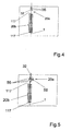
- Fig. 4 shows a modification of the embodiment of FIG. 2.
- the withdrawal godet 54 is not heated.
- Fig. 5 also shows a modification of the embodiment of Fig. 2.
- the withdrawal godet 54 is not heated.
- the unheated draw pins 56 are arranged in front of the heater 20b.
- the wrap of the middle draw pin is a heated plate 58, so that both the thread and indirectly the draw pins are heated.
- the method is modifiable to the effect that the draw pins 56 can be omitted.
- the thread is then passed over the heated plate 58 with little contact or without contact.
- FIGS. 4 and 5 which in each case replace the bordered part according to FIG. 2, are stretching pins and heating means - in this regard, reference is made to FIG. 1 - between withdrawal godet 54 and drawing godet 16.
- the withdrawal godet 54 is heated to a temperature in the range between 70 and 120 °.
- the withdrawal godets 16 may be heated at a temperature of about 150 ° ⁇ 40 ° C to achieve a shrinkage and heat fixation of the thread.
- this is not the subject of the invention.
- the thread is taken up galettly at a take-off speed of more than 5,000 m / min directly from the winding shown by the contact roller 28 and the spool 33.
- the stretching starts already in the spinning zone.
- the first stage of the heat treatment is formed by the entrained spin heat.
- the leadership of the thread over a curved surface can be omitted.
- the thread is then passed through an eyelet or thread guide 8 to the second stage of the heat treatment by means of the heater 20b.
- the heat treatment takes place in that the thread 1 is guided essentially over the heating surface 117.
- the heating surface 117 has a surface temperature that is above the melting temperature of the thread material.
- the thread is wound directly onto the spool 33.
- take-off speeds in the range between 6,000 to 7,500 mm / min can be achieved.
- the heater 20b may be formed in two stages, with both stages of approximately the same length, i. Are 300 to 500 mm long or deliberately short in the feeder and longer in the following zones, so that a strong increase of the intake temperature compared to the following zones is possible.
- the temperature control is done so that in the input-side stage, the surface temperature is 450 to 550 ° C and in the output side stage, the surface temperature is 400 to 500 ° C.
- the thread is guided at a small distance to the respective surface, for example at a distance of 0.5 to 3.5 mm.
- the heater 20b will be described with reference to FIG.
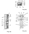
- the heating device 20b may consist of several, here two track sections 114a and 114b lying one behind the other in the thread running direction. These are of different length, but otherwise the same cross-sectional shape.
- the purpose of such a two-part arrangement may be to heat the heater 20b differently in different length ranges in order to treat the thread 1 at a heat profile that satisfies its properties. This means that more than the two sections shown can be used.
- the angle formed by the two heating rails 114 to each other is set identically at each processing point of the spinning-stretching machine, so that threads of the same quality are produced on all processing points.
- For fixing the two heating rails 114 is a mounting rail 158.
- the mounting rail has a U-shaped cross section.
- the heating rails 114 are secured to the bottom of the mounting rail with spacers 160. By dimensioning the spacers and their position relative to the heating rail 114, the inclination of the heating rail 114 with respect to the straightened Fixed mounting rail 158.
- the two heating rails 114 with respect to the mounting rail opposite slope and form together an obtuse angle.
- the mounting rail 158 thus serves for a precise attachment of the two heating rails. Since the mounting rail 158 has a U-shaped profile, but it also surrounds the two heating rails. Therefore, the mounting rail 158 also serves the temperature equalization over the length and width of the heating rails.
- the mounting rail is surrounded by insulation.
- rod-shaped spacers 140 the longitudinal groove 112. Nutengrund, d. H. bridge the heating surface 117 and set the yarn path at an exact distance from the bottom of the groove.
- some or all yarn guides 132 with a circumferential leading edge for. B. a circumferential groove 142 (Fig. 3a) may be provided, the height of the groove bottom is tuned with the predetermined by the guide bodies 140 height of the thread path. In this way, the thread, which is guided in the groove, additionally guided by the side edges of the groove.
- the circumferential grooves have the same depth over the circumference, so they are concentric with the yarn guides 132.
- the circumferential grooves with varying in the course of the circumference depth, z. B. in that the groove bottom is indeed circular cylindrical but eccentric to the thread guides 132 is cut.
- the possibility of a fine adjustment of the contact between the thread 131 and thread guides 132 and the zigzag threadline is given by turning the thread guide.
- the yarn guides 132 could, for example, via a connecting linkage (not shown) rotate together and to the same extent.
- the heater is housed in an insulating box (not shown) in which it is in a heat-insulating material, eg
- the insulating box can be provided with a flap that allows it to open to provide access to the heater and insert the thread. Furthermore, the insulating box with its laying over the heater parts for axially fixing the yarn guide 132 in the rail 114.
- the insulating box is provided with slots that are aligned with the center plane and bevels 134 of the yarn guide 132 and allow it to be treated Insert thread 138 between the thread guides 132.
- the slots are provided on their side walls with wear-resistant insulating.
- heating elements 124, 126 necessary electrical contacts are optionally housed in the insulating box 144.
- the contact surfaces with which the yarn guides touch the yarn have a relatively large diameter.
- the heating rail has on its side remote from the longitudinal groove 112 side two grooves which lie substantially below the thread guide grooves 112. In these grooves heating elements 124 and 126 are inserted.
- the heating elements are clamped by a mounting rail 159, which extends over the entire length of the heating rail.
- a mounting rail 159 which extends over the entire length of the heating rail.
- the mounting plate grooves which surround the heating elements 124, 126.
- the distance of the thread to the heating surface 117 is very small.
- the distance is in the range between 0.5 to 5 mm.
- the upper value is not more than 3.5 mm in order to achieve a good heat transfer and an accurate trouble-free temperature control. This results in the correspondingly high temperature of the heating rail of more than 350 ° C shock-like heating.
- the yarn guides 132 may be at least partially omitted or removed if they have a negative influence. On the one hand, they contribute to calming the yarn path and heating of the yarn by running contact and, on the other hand, have only a slight friction on the yarn as a result of the low looping. The essence, however, is the non-contact guide in close proximity to the highly heated heating surface.
Description
Die Erfindung betrifft ein Verfahren und eine Vorrichtung zum Heizen eines synthetischen Fadens nach dem Oberbegriff der Ansprüche 1 bzw. 19.The invention relates to a method and a device for heating a synthetic thread according to the preamble of
Dieses Verfahren und diese Vorrichtung sind bekannt durch z.B. das US-Patent 3 103 407.This method and apparatus are known by e.g. U.S. Patent 3,103,407.
Bei dem Verfahren bzw. der Vorrichtung wird ein frisch gesponnener synthetischer Faden (Polyester) mittels einer Abzugsgalette aus einer Spinnzone in eine Verstreckzone gefördert und zwischen der Abzugsgalette und einer Verstreckgalette verstreckt. Hierbei wird der Faden mittels der beheizten Abzugsgalette und einer direkt anschließenden beheizten Metallplatte in zwei Stufen durch Kontakt aufgeheizt. Die Abzugsgalette ist hierbei auf eine Temperatur von 60 bis 90 °C und die Metallplatte auf eine Temperatur von 160 bis 200 °C erhitzt. Die Abzugsgeschwindigkeit liegt im Bereich von kleiner 1.000 m/min.In the method and the device, a freshly spun synthetic thread (polyester) is conveyed by means of a Abzugsgalette from a spinning zone in a drawing zone and stretched between the Abzugsgalette and a Verstreckgalette. Here, the thread is heated by means of the heated withdrawal godet and a directly adjacent heated metal plate in two stages by contact. The withdrawal godet is in this case heated to a temperature of 60 to 90 ° C and the metal plate to a temperature of 160 to 200 ° C. The take-off speed is in the range of less than 1,000 m / min.
Bei diesem Verfahren ist von Nachteil, daß die Aufheizung des Fadens ausschließlich vom Kontakt zwischen den beheizten Oberflächen und dem Faden abhängig ist. Außerdem führt die große Berührlänge und die Kontaktkraft zu erhöhten Fadenreibungen, die sich nachteilig auf die Fadenqualität auswirken. Diese Effekte verstärkt sich schnell bei höheren Abzugsgeschwindigkeiten, so daß eine gleichmäßige Wärmeübertragung nicht möglich ist.In this method, it is disadvantageous that the heating of the thread depends exclusively on the contact between the heated surfaces and the thread. In addition, the large contact length and the contact force leads to increased yarn friction, which adversely affect the quality of the thread. These effects increase rapidly at higher take-off speeds, so that even heat transfer is not possible.
Die Aufgabe der Erfindung besteht darin, beim thermischen Behandeln eines laufenden synthetischen Fadens - es kann sich dabei um Polyester, insbesondere aber auch Polyamid, Polytrimethylenterephthalat und Polypropylen handeln - eine gleichmäßige Aufheizung des Fadens mit entsprechend gleichmäßiger Verstreckung und gleichmäßigen, gut einstellbaren Fadeneigenschaften zu erreichen.The object of the invention is the thermal treatment of a running synthetic thread - it may be polyester, but in particular also polyamide, polytrimethylene terephthalate and polypropylene act - to achieve a uniform heating of the thread with a correspondingly uniform stretching and uniform, well-adjustable thread properties.
Die Lösung der Aufgabe ergibt sich aus den Ansprüchen 1 und 19.The solution of the problem arises from the
Hierin ist vorgesehen, daß die Oberflächentemperatur mindestens einer der Heizoberflächen höher ist als die Schmelztemperatur des Fadenmaterials, vorzugsweise höher als 100 Kelvin oberhalb der Schmelztemperatur des Fadenmaterials und daß der Faden dabei einer Fadenzugkraft unterworfen wird, die zur plastischen Verformung erforderlich ist.It is envisaged that the surface temperature of at least one of the heating surfaces is higher than the melting temperature of the thread material, preferably higher than 100 Kelvin above the melting temperature of the thread material and that the thread is subjected to a thread tension required for plastic deformation.
Durch die hohe Temperatur der Heizoberfläche wird eine schockartige Aufheizung des Fadens unmittelbar kurz nach Eintritt in die Heizzone bewirkt. Einerseits kann dadurch der sogenannte Streckpunkt genau lokalisiert werden. Der Streckpunkt ist ein sehr enger Bereich des Fadens, in dem die plastische Verformung durch gleichmäßiges Fließen beginnt. Andererseits führt die schockartige Aufheizung dazu, das Gefügeumwandlungen bevorzugt stattfinden. Die reibungsbedingte mechanische Beanspruchung des Fadens wird auf ein Minimum reduziert, so daß die Fadenzugkraft, die zur plastischen Verformung erforderlich ist, einen stabilen Verlauf aufweist.Due to the high temperature of the heating surface, a shock-like heating of the thread is effected immediately after entering the heating zone. On the one hand, this allows the so-called draw point to be precisely located. The draw point is a very narrow portion of the thread where plastic deformation begins by smooth flow. On the other hand, the shock-like heating causes structural transformation to take place preferentially. The friction-induced mechanical stress of the thread is reduced to a minimum, so that the yarn tension, which is required for plastic deformation, has a stable course.
Ein besonderer Vorteil liegt darin, daß bei der kontinuierlichen Verstreckung und Fixierung die Fadenzugkraft nicht erhöht zu werden braucht sondern im wesentlichen konstalt bleiben kann. Aufgrund der schockartigen Wärmebehandlung wird mit der Verstreckspannung auch bereits eine ausreichend gute Fixierwirkung erzielt. Ein weiterer Vorteil liegt darin, daß Mittel, wie z. B. Galetten, zur Erhöhung der Fadenzugkraft zwischen den einzelnen Stufen der Wärmebehandlung entfallen können.A particular advantage is that in the continuous drawing and fixing the yarn tension does not need to be increased but can remain substantially constant. Due to the shock-like heat treatment, a sufficiently good fixing effect is achieved with the draw tension. Another advantage is that means such. As godets, can be omitted to increase the yarn tension between the individual stages of the heat treatment.
Die Verfahrensvariante nach Anspruch 3 kann überall dort vorteilhaft eingesetzt werden, wo Materialien verarbeitet werden, wie z. B. Polypropylen, die eine Nachverstreckung erfordern.The process variant according to
Die Verfahrensvariante nach Anspruch 4 hat den Vorteil, daß die Wärmebehandlung in der ersten Stufe insbesondere durch einen beheizten Streckstift derart erfolgen kann, daß trotz geringer Berührlänge und hohen Abzugsgeschwindigkeiten die hohen Oberflächentemperaturen eine Ausbildung des Streckpunktes an dem Streckstift bewirken. Der Streckstift kann eine gekrümmte Oberfläche haben mit einem Radius von beispielsweise 10 cm oder sogar weit höher. Er ist ortsfest und nicht drehend angebracht. Sein Mantel wird von dem Faden teilweise berührt bzw. umschlungen. Aufgrund der hohen Oberflächentemperaturen kann die Berührlänge und die Kontaktkraft sehr klein gehalten werden. Hierdurch wird der Verschleiß der Streckstifte gemindert. Außerdem stellen sich sehr geringe Reibungskräfte an dem Faden ein, so daß Fadenbeschädigungen vermieden werden.The process variant according to
Es wird ausdrücklich darauf hingewiesen, daß der Streckstift auch durch eine Platte ersetzt werden kann, die vom Faden berührt wird.It is expressly understood that the draw pin can also be replaced by a plate which is touched by the thread.
Die Erfindung wendet sich bewußt ab von der "nur"-kontaktfreien Fadenführung. Gemäß Anspruch 5 erfolgt die Wärmerübertragung in der ersten Stufe durch Kontakt, der so gestaltet ist, daß sich nur geringe Reibungskräfte an dem Faden ergeben. Die erste Stufe der Wärmebehandlung kann insbesondere durch eine heiße Galette erfolgen, durch die der Faden von der Spinndüse abgezogen wird. Diese Galette liegt an einer Stelle, an der der frisch gesponnene Faden wieder wesentlich erkaltet ist (ca. 40 °C). Diese Galette kann auf eine Temperatur von 70 bis 120 °C aufgeheizt werden. Durch eine nachfolgende Verstreckgalette wird der Faden von der ersten Galette mit einer solchen Fadenzugkraft abgezogen, daß sich unmittelbar beim Ablauf des Fadens von der Galette der Streckpunkt ausbildet. Alternativ kann an die Stelle der Abzugsgalette ein von innen beheizter Streckstift oder eine beheizte Platte treten. Die Berührlänge am Streckstift ist dabei so gering, daß die entstehenden Reibungskräfte gerade ausreichen, daß an dem Streckstift das Fließen erstmals eintritt und sich demgemäß ein Streckpunkt ausbildet. Der Streckstift wirkt also als Bremsfläche, ähnlich der DE 38 23 337 = Bag. 1590. In der zweiten Stufe wird der Faden dagegen im wesentlichen kontaktlos, d.h. mit sehr genauer Führung in engem Abstand zu einer Heizoberfläche geführt, die auf eine Temperatur zwischen 350 und 550 °C erhitzt ist. Der Abstand zwiwschen dem Faden und der Heizoberfläche liegt im Bereich von 0,5 bis 3,5 mm, so daß bei Eintritt in die Heizzone der Faden schockartig erhitzt wird.The invention consciously turns away from the "only" contact-free thread guide. According to
Die Führung des Fadens geschieht durch Fadenführer, die zum einen für eine Laufruhe des Fadens, zum anderen aber auch für den genauen Abstand zu der Heizoberfläche sorgen.The leadership of the thread is done by thread guides, on the one hand for a smooth running of the thread, on the other hand, but also ensure the exact distance to the heating surface.
In einer dritten Stufe kann der Faden sodann in einer anderen Ausführungsform ebenfalls kontaktfrei und in engem Abstand zu einer weiteren Heizoberfläche geführt werden, die auf eine Temperatur zwischen 300 und 500 °C erhitzt ist.In a third stage, the thread may then also be guided without contact and in close proximity to another heating surface, which is heated to a temperature between 300 and 500 ° C in another embodiment.
Die Ausführung nach Anspruch 8 erlaubt eine sehr genaue Einstellung des Verstreckverhältnisses. Der direkt beheizte Streckstift führt auch bei Abzugsgeschwindigkeiten oberhalb 5.000 m/min sicher zur Ausbildung des Streckpunktes.The embodiment according to
Die Verfahrensvariante nach Anspruch 9 hat den Vorteil, daß größere Umschlingungswinkel zur Erzeugung hoher Fadenzugkräfte möglich sind. Die Verfahrensmodifikation nach Anspruch 11 bietet den Vorteil, daß die mitgeführte Spinnwärme bereits in der ersten Stufe der Wärmebehandlung genutzt werden kann. Die Führung des Fadens über eine gekrümmte Heizoberfläche kann hierbei entfallen. Hiermit können Abzugsgeschwindigkeiten im Bereich von 6.000 bis 7.500 m/min erreicht werden.The process variant according to
Die Weiterbildung nach Anspruch 12 ergibt eine sehr einfache Verfahrensführung.The development according to claim 12 results in a very simple procedure.
Die Verfahrensvariante gemäß Anspruch 14 besitzt den Vorzug, daß der Faden bei geringer Verstreckspannung einen genau lokalisierten Streckpunkt ausbildet und. bereits in der ersten Stufe der Verstreckung aufgrund der schockartigen Erwärmung eine bevorzugte Gefügeumwandlung erfährt.The process variant according to
Das Verfahren läßt sich auf alle gängigen Polymertypen anwenden. Für die mechanischen Eigenschaften von Fäden kann es vorteilhaft sein, daß diese aus einer Rezeptur verschiedener Polymere ersponnen werden. Beispielsweise ist bekannt, daß die Beigabe von bis zu 5 % PBT (Polybuthylenterephtalat) zu PET die Spinnbarkeit und die elastischen Eigenschaften der Fasern verbessert.The method can be applied to all common types of polymers. For the mechanical properties of threads, it may be advantageous that they are spun from a recipe of different polymers. For example, it is known that the addition of up to 5% PBT (polybutylene terephthalate) to PET improves the spinnability and elastic properties of the fibers.
Mit diesem Verfahren können bevorzugt Polypropylene mit einer engen Molekulargewichtsverteilung im Bereich kleiner als 3, insbesondere aus Metallocene-Basis hergestellte Typen verarbeitet werden.Polypropylene having a narrow molecular weight distribution in the range of less than 3, in particular metallocene-based, types can preferably be processed by this process.
Die Vorrichtung zeichnet sich dadurch aus, daß hier eine sehr kurze Heizeinrichtung ermöglicht wird, die aber andererseits durch ihre Ausgestaltung den Vorteil hat, daß eine sehr gezielte, auf die Geschwindigkeit des Fadens abgestimmte Temperaturführung im Faden und eine über die Länge des Fadens sehr gleichmäßige Erwärmung ermöglicht wird. Die schockartige Wärmezuführ bei Eintritt des Fließens verhindert eine Störung der Kristallstuktur und ermöglicht damit eine optimale Orientierung der Fadenmoleküle.The device is characterized in that here a very short heater is made possible, but on the other hand has the advantage of its design that a very targeted, matched to the speed of the thread temperature control in the thread and over the length of the thread very uniform heating is possible. The shock-like heat supply at the onset of flow prevents disturbance of the crystal structure and thus allows optimal orientation of the thread molecules.
Die schockartige Wärmezufuhr in der ersten Stufe der Erwärmung führt schlagartig zum Erreichen des Streckpunktes und vermindert zudem die Berührlänge und Kontaktkraft.The shock-like heat supply in the first stage of heating leads abruptly to reach the drawing point and also reduces the contact length and contact force.
Die Weiterbildung der Vorrichtung nach Anspruch 22 hat den Vorteil, daß sie einfach bedient werden kann, das insbesondere der Faden einfach eingelegt werden kann. Auch die Überwachung ist gut möglich.The development of the device according to claim 22 has the advantage that it can be easily operated, in particular, the thread can be easily inserted. The monitoring is also possible.
Die Ausgestaltung nach Anspruch 23 sorgt für eine ruhige Fadenführung und erlaubt darüber hinaus eine den Bedürfnissen angepaßte Temperaturführung. Hierdurch lassen sich Festigkeit, Dehnbarkeit und Schrumpfneigung des Fadens sehr weitgehend beeinflussen und auf gewünschte Werte einstellen.The embodiment according to
Die Ausgestaltung nach Anspruch 24 dient der Fixierung des Fadenlaufs relativ zu der beheizten Oberfläche aber auch zur Beruhigung des Fadenlaufs.The embodiment according to claim 24 serves to fix the yarn path relative to the heated surface but also to calm the yarn path.
Die Ausgestaltung nach Anspruch 25 und 26 ist maschinentechnisch einfach dargestellt. Die Umschlingung des Fadens an dem Streckstift kann durch die Positionierung des Streckstiftes sehr einfach so eingestellt werden, daß unter Berücksichtigung der Temperatur des Streckstiftes die Fadenzugkraft so weit erhöht wird, daß sich an dem Streckstift der Streckpunkt ausbildet. Bei dieser Ausführung ist es auch möglich, ohne Abzugsgalette zu arbeiten, was zum einen maschinentechnisch einfach ist, zum anderen aber auch erlaubt, die aus der Spinnzone mitgeführte Wärme im Faden auch bereits für die Ausbildung des Streckpunktes zu nutzen.The embodiment according to
Erfolgt die Versteckung nach Anspruch 29, ergeben sich sehr weitgehende Einstellmöglichkeiten für das Verstreckverhältnis und die dadurch hervorgerufene Orientierung und die sonstigen Eigenschaften des Fadens.If the hiding according to
Im folgenden werden Ausführungsbeispiele der Erfindung anhand der Figuren 1 bis 6 beschrieben.
- Fig. 1
- zeigt schematisch ein Spinnverfahren und die dazu erforderlichen Vorrichtungsteile in dem Verfahren und Vorrichtung nach dieser Erfindung angewandt werden;
- Fig. 2
- zeigt eine Modifikation des Verfahrens und der Vorrichtung;
- Fig. 3
- zeigt eine Ausführungsform einer Heizeinrichtung;
- Fig. 4
- zeigt eine Modifikation der Verstreckzone und deren Vorrichtung;
- Fig. 5
- zeigt eine weitere Modifikation der Verstreckzone und der Vorrichtung;
- Fig. 6
- zeigt eine galettenlose Verfahrensvariante und deren Vorrichtungsteile.
- Fig. 1
- Fig. 12 schematically shows a spinning process and the apparatus parts required therefor in the method and apparatus according to this invention;
- Fig. 2
- shows a modification of the method and the device;
- Fig. 3
- shows an embodiment of a heater;
- Fig. 4
- shows a modification of the drawing zone and its device;
- Fig. 5
- shows a further modification of the drawing zone and the device;
- Fig. 6
- shows a galettelose process variant and its device parts.
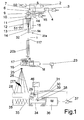
Ein Faden 1 wird aus einem thermoplastischen Material gesponnen. Das thermoplastische Material wird durch eine Fülleinrichtung 2 dem Extruder 3 aufgegeben. Der Extruder 3 ist durch einen Motor 4 angetrieben. Der Motor 4 wird durch eine Motorsteuerung 49 gesteuert. In dem Extruder 3 wird das thermoplastische Material aufgeschmolzen. Hierzu dient zum einen die Verformungsarbeit (Scherenergie), die durch den Extruder in das Material eingebracht wird. Zusätzlich ist eine Heizeinrichtung 5, z. B. in Form einer Widerstandsheizung vorgesehen, die durch eine Heizungssteuerung 50 angesteuert wird. Durch die Schmelzeleitung 6, in der ein Drucksensor 7 zur Messung des Schmelzedruckes für eine Druck-Drehzahlsteuerung des Extruders vorgesehen ist, gelangt die Schmelze zu der Zahnradpumpe 9, die durch Pumpenmotor 44 angetrieben wird. Der Pumpenmotor wird durch die Pumpensteuerung 45 derart angesteuert, daß die Pumpendrehzahl feinfühlig einstellbar ist. Die Pumpe 9 fördert den Schmelzestrom zu dem beheizten Spinnkasten 10, an dessen Unterseite sich die Spinndüse 11 befindet. Aus der Spinndüse 11 tritt die Schmelze in Form von feinen Filamentsträngen 12 aus. Die Filamentstränge durchlaufen einen Kühlschacht 14. In dem Kühlschacht 14 wird durch Anblasen ein Luftstrom 15 quer oder radial auf die Filamentschar 12 gerichtet. Dadurch werden die Filamente gekühlt.A
Am Ende des Kühlschachtes 14 wird die Filamentschar durch eine Präparationswalze 13 oder einen Präparationsstift zu einem Faden 1 zusammengefaßt und mit einer Präparationsflüssigkeit versehen.At the end of the cooling
Nur für die Ausführung nach Fig. 1 gilt:Only for the embodiment according to FIG. 1:
Der Faden wird aus dem Kühlschacht 14 und von der Spinndüse 11 durch eine Abzugsgalette 16 abgezogen. Der Faden umschlingt die Abzugsgalette 16 mehrfach. Dazu dient eine verschränkt zu der Galette 16 angeordnete Überlaufrolle 17. Die Überlaufrolle 17 ist frei drehbar. Die Galette 16 wird durch Galettenmotor 18 und Frequenzgeber 23 angetrieben mit einer voreinstellbaren Geschwindigkeit. Diese Abzugsgeschwindigkeit ist um ein Vielfaches höher als die natürliche Austrittsgeschwindigkeit der Filamente 12 aus der Spinndüse 11 und höher als die Filamentgeschwindigkeit nach Erstarrung in der Anblasung.The thread is withdrawn from the cooling
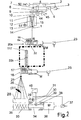
Nur für die Ausführung nach Fig. 2 gilt:Only for the embodiment according to FIG. 2:
Der Faden wird aus dem Kühlschacht 14 und von der Spinndüse 11 durch eine Abzunggalette 54 abgezogen. Der Faden umschlingt die Abzuggalette 54 mehrfach. Dazu dient eine verschränkt zu der Galette 54 angeordnete Überlaufrolle 55. Die Überlaufrolle 55 ist frei drehbar. Die Galette 55 wird durch einen Galettenmotor mit einer voreinstellbaren Geschwindigkeit abgezogen. Diese Abzugsgeschwindigkeit ist um ein Vielfaches höher als die natürliche Austrittsgeschwindigkeit der Filamente 12 aus der Spinndüse. Von der Abzuggalette 54 gelangt der Faden durch die Heizeinrichtung 20b zu der weiteren Galette 16, die hier als Verstreckgalette bezeichnet wird. Die Verstreckgalette 16 ist mit einer höheren Geschwindigkeit angetrieben als die zuvorbeschriebene Galette 54. Dadurch wird der Faden zwischen den beiden Galetten 54 und 16 verstreckt.The thread is withdrawn from the cooling
Für beide Ausführungen gilt wiederum:For both versions applies again:
Von der Verstreckgalette 16 in Fig. 2 bzw. der Abzugsgalette 16 in Fig. 1 gelangt der Faden 1 zu dem sogenannten "Kopffadenführer" 25 und von dort in das Changierdreieck 26. In Fig. 1 ist die Changiereinrichtung 27 nicht dargestellt. Es handelt sich dabei um gegensinnig rotierende Flügel, die den Faden 1 über die Länge der Spule 33 hin- und herführen. Dabei umschlingt der Faden hinter der Changiereinrichtung 27 eine Kontaktwalze 28. Die Kontaktwalze 28 liegt auf der Oberfläche der Spule 33 an. Sie dient zur Messung der Oberflächengeschwindigkeit der Spule 33. Die Spule 33 wird auf einer Hülse 35 gebildet. Die Hülse 35 ist auf einer Spulspindel 34 aufgespannt. Die Spindel 34 wird durch Spindelmotor 36 und Spindelsteuerung 37 derart angetrieben, daß die Oberflächengeschwindigkeit der Spule 33 konstant bleibt. Hierzu wird als Regelgröße die Drehzahl der frei drehbaren Kontaktwalze 28 an der Kontaktwalzenwelle 29 mittels einer ferromagnetischen Einlage 30 und einem magnetischen Impulsgeber 31 abgetastet.From the
Es wird darauf hingewiesen, daß die Changiereinrichtung 27 auch eine übliche Kehrgewindewalze mit einem in der Kehrgewindenut über den Changierbereich hin- und hergeführten Changierfadenführer sein kann.It should be noted that the traversing
In Figur 1 wird als Zustandparameter der Spule 33 der Durchmesser laufend erfaßt oder eine von dem Durchmesser abgeleitete Größe. Zur Messung des Durchmessers wird die Drehzahl der Spindel 34 und die Drehzahl der Kontaktwalze 28, die auf der Oberfläche der Spule anliegt, gemessen. Hierzu dienen ferromagnetische Einlagen 30, 38 in der Spindel 34 wie auch der Kontaktwalze 28 sowie entsprechende Impulsgeber 31, 39. Während die Drehzahl der Kontaktwalze 28 gleichzeitig als Regelgröße für die Verstellung des Spindelmotors 36 über Spindelsteuerung 37 dient, wird die Drehzahl der Spindel 34 - worauf hier nicht weiter eingegangen wird, zur Steuerung der Changiereinrichtung 27 verwandt.In FIG. 1, the diameter of the
Wie die Ausführung nach Fig. 1 zeigt, liegen zwischen dem Kühlschacht 14 und der Abzugsgalette 16 Streckstifte 56 und eine Heizeinrichtung 20b. Der letzte der Streckstifte 56 weist eine beheizte Heizoberfläche 32 auf. Die Streckstifte sind bevorzugt nicht drehbar und bevorzugt fest angeordnet. Sie werden von dem Faden teilweise umschlungen. Durch Verstellung des ersten Steckstiftes senkrecht zum Fadenlauf kann der Umschlingungswinkel und damit die Berührlänge an den Oberflächen jedes Steckstiftes in gewünschter weise verkleinernt oder vergrößert werden. Bei einer Anordnung von drei Streckstiften (Fig. 5) wird vorzugsweise der mittlere Streckstift verstellt. In Fig. 1, 4 und 5 ist der Versatz übertrieben dargestellt. In Wirklichkeit genügt ein geringer Versatz. Mindestens einer der Streckstifte, vorzugsweise der letzte, ist - wie gesagt - beheizt. Die Temperatur, auf die der Faden erhitzt wird, liegt höher als die Glasübergangstemperatur des Fadens, die für Polyester bei 55 und unter 120 °C liegt.As the embodiment of FIG. 1 shows, 16 stretching
Bei einer Oberflächentemperatur der Heizoberfläche 32 des beheizten Streckstiftes 56, die über der Schmelztemperatur des Fadenmaterials liegt, werden Abzugsgeschwindigkeiten von bis über 5.000 m/min erreicht. In diesem Fall wird mit sehr geringen Berührlängen an den Streckstiften 56 gefahren.With a surface temperature of the
Bei der Ausführung nach Fig. 2 liegt die Heizeinrichtung 20b zwischen der Abzugsgalette 54 und der Verstreckgalette 16. In dieser Ausführung ist die Oberfläche 32 der Abzugsgalette 54 beheizt, so daß sich der Streckpunkt des Fadens unmittelbar hinter oder auf der Galette ausbildet. Zur weiteren Wärmebehandlung wird der Faden durch die Heizeinrichtung 20b geführt.In the embodiment of FIG. 2, the
Fig. 4 zeigt eine Modifikation der Ausführung nach Fig. 2. Hierbei ist die Abzugsgalette 54 nicht beheizt. Stattdessen befinden sich vor der Heizeinrichtung 20b Streckstifte 56, von denen mindestens einer eine beheizte Heizoberfläche 32 aufweist. Im übrigen entsprechen diese Streckstifte in ihrer Ausführung und Temperaturführung den Streckstiften, die in Zusammenhang mit Fig. 1 beschrieben worden sind.Fig. 4 shows a modification of the embodiment of FIG. 2. Here, the
Eine vorteilhafte Weiterbildung der Anordnung der Figur 4 ist dann gegeben, wenn die Streckstifte 56 im Fadeneintrittsbereich der Heizeinrichtung 20b angeordnet werden. Der Streckpunkt des Fadens wird sich unmittelbar hinter dem letzten Streckstift 56 ausbilden, so daß die Verstreckung und die Fixierung in der unmittelbar folgenden Wärmebehandlung erfolgt.An advantageous development of the arrangement of FIG. 4 is given when the stretching pins 56 are arranged in the thread inlet region of the
Fig. 5 zeigt ebenfalls eine Modifikation der Ausführung nach Fig. 2. Die Abzugsgalette 54 ist nicht beheizt. Vor der Heizeinrichtung 20b sind die unbeheizten Streckstifte 56 angeordnet. Gegenüber der Umschlingungsseite des mittleren Streckstiftes befindet sich eine beheizte Platte 58, so daß sowohl der Faden als auch indirekt die Streckstifte erwärmt werden.Fig. 5 also shows a modification of the embodiment of Fig. 2. The
Bei dieser Ausführung ist das Verfahren dahingehend modifizierbar, daß die Streckkstifte 56 entfallen können. Der Faden wird dann mit geinger Berührung oder auch berührungslos über die beheizte Platte 58 geführt.In this embodiment, the method is modifiable to the effect that the draw pins 56 can be omitted. The thread is then passed over the
Bei den Ausführungen nach Fig. 4 und 5, die jeweils den umrandeten Teil nach Fig. 2 ersetzen, liegen Streckstifte und Heizeinrichtung - insofern wird auf Fig. 1 verwiesen - zwischen Abzugsgalette 54 und Verstreckgalette 16.In the embodiments according to FIGS. 4 and 5, which in each case replace the bordered part according to FIG. 2, are stretching pins and heating means - in this regard, reference is made to FIG. 1 - between
Bei der Ausführung nach Fig. 2 ist die Abzugsgalette 54 beheizt auf eine Temperatur im Bereich zwischen 70 und 120 °.In the embodiment according to FIG. 2, the
In beiden Fällen können auch die Abzugsgaletten 16 beheizt sein mit einer Temperatur von ca. 150 ° ± 40 °C, um eine Schrumpfung und Wärmefixierung des Fadens zu ereichen. Dies ist jedoch nicht Gegenstand der Erfindung.In both cases, the
Bei der in Fig. 6 gezeigeten Modifikation wird der Faden galettenlos mit einer Abzugsgeschwindigkeit größer 5.000 m/min direkt von der Aufwicklung, die durch die Kontaktwalze 28 und die Spule 33 gezeigt ist, aufgenommen. Die Verstreckung beginnt bereits in der Spinnzone. Die erste Stufe der Wärmebehandlung wird durch die mitgeführte Spinnwärme gebildet. Die Führung des Fadens über eine gekrümmte Oberfläche kann entfallen. Der Faden wird sodann durch eine Öse oder Fadenführer 8 zu der zweiten Stufe der Wärmebehandlung mittels der Heizeinrichtung 20b geführt. Die Wärmebehandlung erfolgt dadurch, daß der Faden 1 im wesentlichen über die Heizoberfläche 117 geführt wird. Die Heizoberfläche 117 weist eine Oberflächentemperatur auf, die über der Schmelztemperatur des Fadenmaterials liegt. Nach der Verstreckung wird der Faden direkt auf die Spule 33 aufgewickelt. Mit dieser Modifikation werden Abzugsgeschwindigkeiten im Bereich zwischen 6.000 bis 7.500 mm/min erreicht.In the modification shown in Fig. 6, the thread is taken up galettly at a take-off speed of more than 5,000 m / min directly from the winding shown by the
Die Heizeinrichtung 20b kann zweistufig ausgebildet sein, wobei beide Stufen etwa gleich lang, d.h. 300 bis 500 mm lang sind oder bewußt im Einzug kurz und in den Folgezonen länger sind, damit eine starke Überhöhung der Einzugstemperratur im Vergleich zu den Folgezonen möglich ist. Die Temperaturführung geschieht so, daß in der eingangsseitigen Stufe die Oberflächentempratur 450 bis 550 °C und in der ausgangssseitigen Stufe die Oberflächentemperatur 400 bis 500 °C beträgt. Der Faden wird in geringem Abstand zu der jeweiligen Oberfläche geführt, etwa in einem Abstand von 0,5 bis 3,5 mm.The
Die Heizeinrichtung 20b wird anhand Figur 3 beschrieben.The
Wie dargestellt kann die Heizvorrichtung 20b aus mehreren, hier zwei in Fadenlaufrichtung hintereinanderliegenden Schienenabschnitten 114a und 114b bestehen. Diese sind von unterschiedlicher Länge, ansonsten aber gleicher Querschnittsform. Zweck einer solchen zweigeteilten Anordnung kann es sein, die Heizeinrichtung 20b in verschiedenen Längenbereichen unterschiedlich zu erwärmen, um den Faden 1 bei einem seinen Eigenschaften gerechtwerdenden Wärmeprofil zu behandeln. Das heißt: Es können auch mehr als die zwei dargestellten Abschnitte angewandt werden. Dabei ist es von besonderer Wichtigkeit, daß der Winkel, den die beiden Heizschienen 114 zueinander bilden, an jeder Bearbeitungsstelle der Spinn-Streck-Maschine identisch eingestellt wird, damit auf allen Bearbeitungsstellen Fäden gleicher Qualität erzeugt werden. Zur Befestigung der beiden Heizschienen 114 dient eine Befestigungsschiene 158. Dabei handelt es sich um eine Schiene, die die Länge der beiden Heizschienen hat. Die Befestigungsschiene hat einen U-förmigen Querschnitt. Die Heizschienen 114 werden auf dem Grund der Befestigungsschiene mit Abstandshaltern 160 befestigt. Durch die Dimensionierung der Abstandshalter und ihre Position relativ zu der Heizschiene 114 wird die Neigung der Heizschiene 114 im Bezug auf die geradegestreckte Befestigungsschiene 158 festgelegt. Dabei haben die beiden Heizschienen 114 bezüglich der Befestigungsschiene gegensätzliche Neigung und bilden darüber miteinander einen stumpfen Winkel. Die Befestigungsschiene 158 dient also zum einen zur genauen Befestigung der beiden Heizschienen. Da die Befestigungsschiene 158 ein U-förmiges Profil hat, umgreift sie aber auch die beiden Heizschienen. Daher dient die Befestigungsschiene 158 auch der Temperaturvergleichmäßigung über die Länge und Breite der Heizschienen. Die Befestigungsschiene wird mit einer Isolierung umgeben.As shown, the
Es können stabförmige Abstandshalter 140 vorgesehen sein können, die die Längsnut 112. am Nutengrund, d. h. der Heizoberfläche 117 überbrücken und den Fadenlauf in einem genauen Abstand zum Nutengrund festlegen. Alternativ oder zusätzlich können einige oder alle Fadenführer 132 mit einer umlaufenden Führungskante, z. B. einer Umfangsnut 142 (Fig. 3a) versehen sein, deren Höhe vom Nutengrund mit der von den Führungskörpern 140 vorgegebenen Höhe der Fadenlaufbahn abgestimmt ist. Auf die Weise wird der Faden, der in der Nut geführt ist, zusätzlich durch die Seitenkanten der Nut geführt. Die Umfangsnuten haben über den Umfang gleiche Tiefe, sind also konzentrisch zu den Fadenführern 132 ausgebildet. Es ist jedoch auch möglich, die Umfangsnuten mit im Verlauf des Umfangs wechselnder Tiefe auszubilden, z. B. dadurch, daß der Nutengrund zwar kreiszylindrisch aber exzentrisch zu den Fadenführern 132 eingeschnitten wird. In diesem Falle ist durch Verdrehen der Fadenführer die Möglichkeit einer Feineinstellung der Berührung zwischen Faden 131 und Fadenführern 132 und des zickzackförmigen Fadenlaufes gegeben. Dazu ließen sich die Fadenführer 132 beispielsweise über ein sie verbindendes Gestänge (nicht dargestellt) gemeinsam und in gleichem Ausmaß verdrehen.It can be provided rod-shaped
Im übrigen ist die Heizvorrichtung in einem Isolierkasten (nicht gezeigt) untergebracht, in dem sie in einem wärmedämmenden Material, z.B.Moreover, the heater is housed in an insulating box (not shown) in which it is in a heat-insulating material, eg
Glasfasern, eingebettet ist. Der Isolierkasten kann dabei mit einer Klappe versehen sein, der es ermöglicht, ihn zu öffnen, um Zugang zu der Heizvorrichtung zu bieten und den Faden einzulegen. Ferner dient der Isolierkasten mit seinen sich über die Heizvorrichtung legenden Teile zum axialen Festlegen der Fadenführer 132 in der Schiene 114. Dabei ist der Isolierkasten mit Schlitzen versehen, die mit der Mittelebene und den Anschrägungen 134 der Fadenführer 132 fluchten und es ermöglichen, einen zu behandelnden Faden 138 zwischen die Fadenführer 132 einzubringen. Die Schlitze sind an ihren Seitenwänden mit verschleißfesten Isolierplatten versehen.Glass fibers, embedded. The insulating box can be provided with a flap that allows it to open to provide access to the heater and insert the thread. Furthermore, the insulating box with its laying over the heater parts for axially fixing the
Auch die für. die Heizelemente 124, 126 erforderlichen elektrischen Kontakte sind gegebenenfalls in dem Isolierkasten 144 untergebracht.Also for. the
Die Kontaktflächen, mit denen die Fadenführer den Faden berühren, haben einen verhältnismäßig großen Durchmesser. Im Gegensatz dazu besitzt die Zickzacklinie, in der der Faden durch die Überlappung U der aufeinanderfolgenden Fadenführer geführt ist, eine verhältnismäßig kleine Amplitude, bei verhältnismäßig großem Abstand (A) zwischen zwei benachbarten Fadenführern. Dadurch wird erreicht, daß der Umschlingungswinkel, mit welchem der Faden die Fadenführer bzw. die an ihnen gebildeten Kontaktflächen umschlingt, auch in der Summe klein ist.The contact surfaces with which the yarn guides touch the yarn have a relatively large diameter. In contrast, has the zigzag line, in which the thread is guided by the overlap U of the successive yarn guide, a relatively small amplitude, at a relatively large distance (A) between two adjacent yarn guides. This ensures that the wrap angle at which the thread wraps around the thread guides or the contact surfaces formed on them, even in the sum is small.
Die Heizschiene besitzt auf ihrer von der Längsnut 112 abgewandten Seite zwei Nuten, die im wesentlichen unterhalb der Fadenführungsnuten 112 liegen. In diese Nuten sind Heizelemente 124 und 126 eingelegt. Die Heizelemente werden durch eine Befestigungsschiene 159, die sich über die gesamte Länge der Heizschiene erstreckt, festgeklemmt. Dazu besitzt auch die Befestigungsplatte Nuten, welche die Heizelemente 124, 126 umgreifen. Durch Lösen der Befestigungsplatte 159 können die Heizelemente 124, 126 leicht ausgetauscht werden.The heating rail has on its side remote from the
Der Abstand des Fadens zu der Heizoberfläche 117 ist sehr gering. Der Abstand liegt im Bereich zwischen 0,5 bis 5 mm. Vorzugsweise beträgt der obere Wert nicht mehr als 3,5 mm, um einen guten Wärmeübergang und eine genaue störungsfreie Temperaturführung zu erzielen.
Dadurch erfolgt bei der entsprechend hohen Temperatur der Heizschiene von mehr als 350°C eine schockartige Erhitzung. Die Fadenführer 132 können zumindest teilweise auch fortgelassen oder entfernt werden, wenn sie einen negativen Einfluß haben. Sie tragen einerseits zu einer Beruhigung des Fadenlaufs und einer Erwärmung des Fadens durch Laufkontakt bei und haben andererseits nur eine geringe Reibung auf den Faden infolge der geringen Umschlingung.
Das Wesentliche ist jedoch die kontaktfreie Führung in dichter Nachbarschaft zu der hoch-erhitzten Heizoberfläche.The distance of the thread to the
This results in the correspondingly high temperature of the heating rail of more than 350 ° C shock-like heating. The yarn guides 132 may be at least partially omitted or removed if they have a negative influence. On the one hand, they contribute to calming the yarn path and heating of the yarn by running contact and, on the other hand, have only a slight friction on the yarn as a result of the low looping.
The essence, however, is the non-contact guide in close proximity to the highly heated heating surface.
- 11
- Fadenthread
- 22
- Fülleinrichtungfilling
- 33
- Extruderextruder
- 44
- Motorengine
- 55
- Heizeinrichtungheater
- 66
- Schmelzeleitungmelt line
- 77
- Drucksensorpressure sensor
- 88th
- Fadenführerthread guides
- 99
- Pumpe, ZahnradpumpePump, gear pump
- 1010
- Spinnkopf. SpinnkastenSpinning head. spin box
- 1111
- Düse, SpinndüseNozzle, spinneret
- 1212
- Filamente, FilamentstrangFilaments, filament strand
- 1313
- Präparationswalze, PräparationseinrichtungPreparation roller, preparation device
- 1414
- Kühlschachtcooling shaft
- 1515
- Anblasung, LuftstromInjection, airflow
- 1616
- Abzugsgalettegodet
- 1717
- ÜberlaufrolleGuide roll
- 1818
- Antriebsmotordrive motor
- 1919
- Gehäusecasing
- 2020
- Heizeinrichtungheater
- 2121
- Ausgangsschleuseexit lock
- 2222
- Frequenzgeberfrequency generator
- 2323
- Dampfdüsefrother
- 2424
- Fadenkanalthread channel
- 2525
- Kopffadenführer, FadenführerHead thread guide, thread guide
- 2626
- ChangierdreieckTraversing triangle
- 2727
- ChangiereinrichtungTraversing device
- 2828
- Kontaktwalzecontact roller
- 2929
- KontaktwalzenwelleContact roller shaft
- 3030
- ferromagnetische Einlageferromagnetic insert
- 3131
- Impulsgeberpulse
- 3232
- Heizoberfläche, OberflächeHeating surface, surface
- 3333
- SpuleKitchen sink
- 3434
- Spindelspindle
- 3535
- Spulhülsewinding tube
- 3636
- Antriebsmotordrive motor
- 3737
- Spindelsteuerungspindle control
- 3838
- ferromagnetische Einlageferromagnetic insert
- 3939
- Impulsgeberpulse
- 4040
- Eingangsschleuseentry lock
- 4141
- Dampfkanalvapor channel
- 4242
- HeizdampferzeugerHeizdampferzeuger
- 4444
- Pumpenmotorpump motor
- 4545
- Pumpensteuerungpump control
- 4646
- Rechnereinheitcomputer unit
- 4747
- Wasserdüsewater nozzle
- 4848
- ÜberlaufkörperOverflow body
- 4949
- Extrudersteuerungextruder control
- 5050
- Heizungssteuerungheating control
- 5151
- Kühlsteuerungcooling control
- 5252
- Ausgangsschleuseexit lock
- 5353
- Eingangsschleuseentry lock
- 5454
- GaletteGalette
- 5555
- ÜberlaufrolleGuide roll
- 5656
- Streckstiftdraw pin
- 5858
- Platteplate
- 112112
- Längsnutlongitudinal groove
- 114114
- Schienerail
- 116116
- Unterteillower part
- 117117
- Heizoberflächeheating surface
- 118118
- Wandwall
- 120120
- Trennwandpartition wall
- 122122
- Wandwall
- 124124
- Heizelementheating element
- 126126
- Heizelementheating element
- 128128
- Ausnehmungrecess
- 130130
- Schlitzslot
- 132132
- Fadenführer, FührungskörperThread guide, guide body
- 134134
- Anschrägungbevel
- 136136
- Rillegroove
- 140140
- Fadenführer, AbstandhalterThread guide, spacers
- 142142
- Umfangsnutcircumferential groove
- 158158
- Befestigungsschienemounting rail
- 159159
- Befestigungsplattemounting plate
- 160160
- Abstandshalterspacer
Claims (29)
- Method for spinning, drafting and winding a multifilament synthetic thread (1), in which the thread (1), during drafting in a drafting zone, is subjected to multi-stage heat treatment by heated heating surfaces (32, 117), and in which the first heat treatment serves for heating the thread (1) to the region of the glass transition temperature of the thread material, the thread (1) being guided with partial looping (galette, plate or drafting pin) over a heating surface (32), and in which, immediately thereafter, the thread (1) is guided, in the second stage, along an elongate heating surface (117), characterized in that the surface temperature of at least one of the heating surfaces (32, 117) is higher than the melting temperature of the thread material, preferably higher than 100 Kelvin above the melting temperature of the thread material, preferably between 200 and 300 Kelvin above the melting temperature of the thread material, and in that the thread (1) is subjected in the drafting zone to a thread tension force which is required for plastic deformation in or directly downstream of the first stage of heat treatment.
- Method according to Claim 1, characterized in that the thread tension force is essentially constant within the drafting zone.
- Method according to Claim 1, characterized in that the thread tension force is increased within the drafting zone.
- Method according to one of Claims 1 to 3, characterized in that the surface temperature of the first heating surface (32) is higher than the melting temperature of the thread material.
- Method according to one of Claims 1 to 4, characterized in that the surface temperature of the second heating surface (117) is higher than the melting temperature of the thread material.
- Method according to Claim 5, characterized in that the thread (1) is guided along the second heating surface (117) at a distance and essentially without contact.
- Method according to Claim 6, characterized in that the thread (1) is guided along the second heating surface (117) by one or more short guide bodies (132) which are distributed along the heating zone.
- Method according to one of Claims 2, 4 to 7, characterized in that drafting takes place between two galettes (54, 16) and the first of the galettes (54) is unheated, and in that the first stage of heat treatment takes place downstream of the first galette (54) by means of a fixed drafting pin (56) which the thread (1) partly loops around or at least touches.
- Method according to Claim 8, characterized in that the first stage of heat treatment takes place downstream of the first galette (54) by means of a heated plate (58) along which the thread (1) is guided contactlessly.
- Method according to one of Claims 3 to 7, characterized in that drafting takes place between two galettes (54, 16) and, for carrying out the first stage of heat treatment, the first of the galettes (54) is heated at a temperature in the region of the glass transition temperature of the respective polymer, preferably at a temperature of between 60 and 120°C.
- Method according to one of Claims 3 to 7, characterized in that drafting commences in the spinning zone, the take-up speed of the winding lying above 5000 m/min.
- Method according to one of the preceding claims, characterized in that drafting takes place by means of a galette (16) which takes up the freshly spun thread directly at a high speed of more than 3500 m/min from the spinneret, and in that the first stage of heat treatment takes place by means of a fixed drafting pin (56) which the thread partly loops around or at least touches.
- Method according to Claim 12, characterized in that the first stage of heat treatment takes place by means of a fixed plate (58), along which the thread is guided contactlessly.
- Method according to Claim 8 or 12, characterized in that the first stage of heat treatment is formed by a drafting pin (56), the drafting pin being arranged directly at the thread entry within an elongate heating surface (117), and the heating surface temperature being higher than the melting temperature of the thread material.
- Method according to one of the preceding claims, characterized in that the synthetic thread consists of polyester, in particular polyethylene terephthalate.
- Method according to one of Claims 1 to 13, characterized in that the synthetic thread consists of a polyamide (PA 6 or PA 6.6 or a blend of PA types).
- Method according to one of Claims 1 to 13, characterized in that the synthetic thread consists of a polypropylene.
- Method according to one of Claims 1 to 13, characterized in that the synthetic thread consists of a polytrimethyleneterephthalate.
- Spinning, drafting and winding machine for spinning, drafting and winding a multifilament synthetic thread (1), in which the thread (1) is heated in the drafting zone by means of a heating device (20) in a plurality of stages with a thread tension force leading to plastic deformation, characterized in that the heating device (20a) of the first stage is a preferably curved heating surface (32) of which the thread (1) is guided, and in that the heating device (20b) of the second stage is an elongate heating surface (117) with thread guides (132), by means of which the thread (1) is guided contactlessly but in close proximity to the heating surface (117), and in that at least one of the heating surfaces (32, 117) is set at a temperature which is higher than the melting temperature of the thread material, preferably higher than 100 Kelvin above the melting temperature of the thread material, preferably more than 150 Kelvin above the melting temperature of the thread material.
- Device according to Claim 19, characterized in that the heating device (20a) of the first stage of heating is set at a higher temperature than the melting temperature of the thread material.
- Device according to Claim 19 or 20, characterized in that the heating device (20b) of the second stage of heating is set at a higher temperature than the melting temperature of the thread.
- Device according to one of Claims 19 to 21, characterized in that the heating device (20) is formed by an elongate U-shaped or V-shaped rail, in the longitudinal groove of which the thread is guided in an essentially contact-free manner.
- Device according to either one of Claims 19 and 21, characterized in that the heating device (20b) of the second stage is divided in two and is formed from two elongate U-shaped or V-shaped rails (114) which form an obtuse angle between them, and in that thread guides (132) are arranged in the region of the adjacent ends between the two rails (114) and serve for guiding the thread (1) in the longitudinal groove (112) of the two rails (114) in an essentially contact-free manner.
- Device according to either one of Claims 22 and 23, characterized in that the thread (1) is guided along the heating surface (117) by one or more short guide bodies (132, 140) which are distributed along the heating zone.
- Device according to one of Claims 20 to 24, characterized in that the heating device (20a) of the first stage is a heated drafting pin (56), around which the thread (1) is guided with partial looping, and in that the heating surface (32) of the drafting pin is set at a temperature higher than the melting temperature of the thread material, preferably higher than 150 Kelvin above the melting temperature of the thread material.
- Device according to one of Claims 20 to 24, characterized in that the heating device (20a) of the first stage is a heated plate (58), past which the thread (1) is guided contactlessly, and in that the heating surface of the plate is set at a temperature higher than the melting temperature of the thread material, preferably higher than 150 Kelvin above the melting temperature of the thread material.
- Device according to either one of Claims 25 and 26, characterized in that the drafting zone directly follows the spinning zone, without a take-up device, galette or the like being interposed.
- Device according to either one of Claims 25 and 26, characterized in that the drafting zone is arranged between a take-up device, galette (54) or the like and a galette (16).
- Device according to one of Claims 21 to 24, characterized in that the thread (1) is taken up by a take-up device, galette (54) or the like from the spinning zone and is conveyed into the drafting zone, and in that the take-up device is heated as the first stage of heat treatment.
Applications Claiming Priority (6)
| Application Number | Priority Date | Filing Date | Title |
|---|---|---|---|
| DE19526265 | 1995-07-19 | ||
| DE19526265 | 1995-07-19 | ||
| DE19530817 | 1995-08-23 | ||
| DE19530817 | 1995-08-23 | ||
| DE19542769 | 1995-11-16 | ||
| DE19542769 | 1995-11-16 |
Publications (3)
| Publication Number | Publication Date |
|---|---|
| EP0754790A2 EP0754790A2 (en) | 1997-01-22 |
| EP0754790A3 EP0754790A3 (en) | 2001-09-19 |
| EP0754790B1 true EP0754790B1 (en) | 2006-10-04 |
Family
ID=27215304
Family Applications (1)
| Application Number | Title | Priority Date | Filing Date |
|---|---|---|---|
| EP96110889A Expired - Lifetime EP0754790B1 (en) | 1995-07-19 | 1996-07-05 | Method and apparatus for heating a synthetic yarn |
Country Status (6)
| Country | Link |
|---|---|
| US (2) | US5783127A (en) |
| EP (1) | EP0754790B1 (en) |
| KR (1) | KR970006555A (en) |
| CN (1) | CN1074472C (en) |
| DE (1) | DE59611386D1 (en) |
| TW (1) | TW320654B (en) |
Families Citing this family (19)
| Publication number | Priority date | Publication date | Assignee | Title |
|---|---|---|---|---|
| DE19915762A1 (en) * | 1999-04-08 | 2000-10-12 | Lurgi Zimmer Ag | Cooling system for filament bundles |
| IL149721A0 (en) | 2000-09-15 | 2002-11-10 | First Quality Fibers Inc | Apparatus for manufacturing optical fiber made of semi-crystalline polymer |
| US6740270B2 (en) | 2000-10-10 | 2004-05-25 | Shell Oil Company | Spin draw process of making partially oriented yarns from polytrimethylene terephthalate |
| US6702864B2 (en) | 2000-10-11 | 2004-03-09 | Shell Oil Company | Process for making high stretch and elastic knitted fabrics from polytrimethylene terephthalate |
| US6565073B1 (en) | 2002-04-17 | 2003-05-20 | Meritor Light Vehicle Technology, Llc | Electromagnetic suspension system |
| NL1029276C2 (en) * | 2005-06-17 | 2006-12-19 | Desseaux H Tapijtfab | Method for manufacturing monofilaments, as well as an artificial grass field composed of these. |
| US20090036613A1 (en) | 2006-11-28 | 2009-02-05 | Kulkarni Sanjay Tammaji | Polyester staple fiber (PSF) /filament yarn (POY and PFY) for textile applications |
| ATE540143T1 (en) * | 2008-05-23 | 2012-01-15 | Oerlikon Textile Gmbh & Co Kg | METHOD FOR PULLING OFF AND STRETCHING A MULTIFILE THREAD DURING MELT SPINNING AND A DEVICE FOR CARRYING OUT THE METHOD |
| CN103060977B (en) * | 2013-01-13 | 2015-07-22 | 经纬纺织机械股份有限公司 | Heat conducting wire disk device of full-automatic false twist texturing machine |
| FR3022822B1 (en) | 2014-06-30 | 2016-10-28 | Michelin & Cie | METHOD AND DEVICE FOR MANUFACTURING RUBBER-COATED METAL WIRE |
| KR101647083B1 (en) * | 2014-12-31 | 2016-08-23 | 주식회사 삼양사 | High performance polyethylene fiber, manufacturing method thereof and device for manufacting the same |
| CN105821498B (en) * | 2016-05-27 | 2017-12-15 | 浙江显昱纤维织染制衣有限公司 | A kind of stretching structure of spinning-drawing machine |
| DE102017100487A1 (en) * | 2017-01-12 | 2018-07-12 | Trützschler GmbH & Co Kommanditgesellschaft | Apparatus and method for producing a multicolor yarn |
| DE102017100488A1 (en) | 2017-01-12 | 2018-07-12 | Trützschler GmbH & Co Kommanditgesellschaft | Apparatus and method for producing a textured filament or yarn |
| CN107161816B (en) * | 2017-06-30 | 2019-02-19 | 昆山双路自动化科技有限公司 | Automatic haircuts machine |
| EP3758445B1 (en) * | 2018-02-23 | 2023-09-06 | TMT Machinery, Inc. | Heating roller and spun yarn drawing device |
| US20210319997A1 (en) * | 2018-08-21 | 2021-10-14 | Bc Machining Technologies Inc. | Method and apparatus for producing filament array |
| CN111155181B (en) * | 2020-01-20 | 2023-10-10 | 宁波海格拉新材料科技有限公司 | Fiber thermal enhancement equipment and thermal treatment method |
| CN115012047B (en) * | 2022-06-28 | 2024-01-09 | 湖州市中跃化纤有限公司 | Production process of high-strength low-shrinkage FDY multi-head spinning female yarn |
Family Cites Families (14)
| Publication number | Priority date | Publication date | Assignee | Title |
|---|---|---|---|---|
| US2811409A (en) * | 1952-12-31 | 1957-10-29 | Eastman Kodak Co | Spinning of acrylonitrile polymer fibers |
| NL258099A (en) * | 1959-11-25 | |||
| US3522342A (en) * | 1967-07-03 | 1970-07-28 | Nypel Inc | Apparatus and method for making bristles having a filler |
| DE2925006C2 (en) * | 1979-06-21 | 1983-06-30 | Akzo Gmbh, 5600 Wuppertal | Process for the production of melt-spun and molecularly oriented drawn, crystalline filaments |
| DE3346677A1 (en) * | 1983-12-23 | 1985-07-04 | Barmag Barmer Maschinenfabrik Ag, 5630 Remscheid | Process for the production of a multifilament man-made fibre |
| US4902461A (en) * | 1987-03-20 | 1990-02-20 | Barmag, Ag | Method for heating an advancing yarn |
| DE3823337A1 (en) * | 1987-07-18 | 1989-01-26 | Barmag Barmer Maschf | Process for the production of smooth yarn |
| DE3823538A1 (en) * | 1988-07-12 | 1990-02-01 | Davy Mckee Ag | PROCESS FOR PREPARING PBT CARPET YARN |
| CA1337498C (en) * | 1989-09-01 | 1995-11-07 | Ephraim Broyer | Thermal treatment of thermoplastic filaments |
| US5277858A (en) * | 1990-03-26 | 1994-01-11 | Alliedsignal Inc. | Production of high tenacity, low shrink polyester fiber |
| EP0580071B1 (en) * | 1992-07-18 | 1999-11-10 | Barmag Ag | Method of production and/or processing as well as winding an endless material of thermoplastic plastic with output of a quality signal as well as a takeup machine |
| JP2692513B2 (en) * | 1992-11-10 | 1997-12-17 | 東レ株式会社 | Method and apparatus for producing polyester fiber |
| DE19506369A1 (en) * | 1994-02-28 | 1995-08-31 | Barmag Barmer Maschf | Heated synthetic yarn draw frame stops detrimental internal reactions |
| DE59601798D1 (en) * | 1995-02-23 | 1999-06-10 | Barmag Barmer Maschf | Process for spinning, drawing and winding a synthetic thread |
-
1996
- 1996-07-05 EP EP96110889A patent/EP0754790B1/en not_active Expired - Lifetime
- 1996-07-05 DE DE59611386T patent/DE59611386D1/en not_active Expired - Fee Related
- 1996-07-15 KR KR1019960028476A patent/KR970006555A/en not_active Application Discontinuation
- 1996-07-17 TW TW085108671A patent/TW320654B/zh not_active IP Right Cessation
- 1996-07-19 US US08/684,389 patent/US5783127A/en not_active Expired - Fee Related
- 1996-07-19 CN CN96110666A patent/CN1074472C/en not_active Expired - Fee Related
-
1998
- 1998-02-17 US US09/024,717 patent/US6012912A/en not_active Expired - Fee Related
Also Published As
| Publication number | Publication date |
|---|---|
| US5783127A (en) | 1998-07-21 |
| DE59611386D1 (en) | 2006-11-16 |
| EP0754790A3 (en) | 2001-09-19 |
| US6012912A (en) | 2000-01-11 |
| CN1074472C (en) | 2001-11-07 |
| KR970006555A (en) | 1997-02-21 |
| CN1145959A (en) | 1997-03-26 |
| EP0754790A2 (en) | 1997-01-22 |
| TW320654B (en) | 1997-11-21 |
Similar Documents
| Publication | Publication Date | Title |
|---|---|---|
| EP0754790B1 (en) | Method and apparatus for heating a synthetic yarn | |
| EP0845550B1 (en) | Process and devices for spinning and winding up a yarn | |
| EP2007935B1 (en) | Method and apparatus for pulling off and drawing a multifilament thread | |
| DE19535143B4 (en) | Apparatus and method for the thermal treatment of fibers | |
| EP1594785B1 (en) | Device for producing and winding synthetic threads | |
| WO2009141426A2 (en) | Method for taking up and drawing a multifilament during melt-spinning, and apparatus for carrying out said method | |
| EP1979513A1 (en) | Apparatus for melt spinning and winding synthetic threads | |
| US5698146A (en) | Method and apparatus for spinning a synthetic multi-filament yarn | |
| EP0940485A2 (en) | Process and apparatus for spinning, drawing and winding up of a yarn | |
| EP0726338A2 (en) | Method for producing a multifilament yarn | |
| DE10053073A1 (en) | Assembly for the production of melt spun thermoplastic filament, to produce more than six, has a tangling unit between the filament gathering guide and the drawing stage | |
| EP1501968B1 (en) | Texturing machine | |
| DE2157663A1 (en) | Method and device for the treatment of unstretched or partially stretched multi-filament thermoplastic yarn in the course of its crimping | |
| DE19506369A1 (en) | Heated synthetic yarn draw frame stops detrimental internal reactions | |
| DE102007014511A1 (en) | Method for melt spinning, involves winding and treatment of multiple multifilter fibers with which multiple filament groups merged into fiber, and are spuned parallely side by side in spinning zone | |
| EP0826802B1 (en) | Process and device for spinning multifilament yarns | |
| EP0731196B1 (en) | Method for the spinning, drawing and winding up of a synthetic yarn | |
| DE2501265A1 (en) | METHOD FOR MANUFACTURING TEXTURED SYNTHETIC YARN | |
| WO2016058873A1 (en) | Method and device for producing a multifilament thread from a polyamide melt | |
| DE3534079C2 (en) | Method for producing flat yarn | |
| WO1999009239A1 (en) | False twist texturing machine and method for producing a textured thread | |
| DE4435923B4 (en) | Apparatus and method for uniformly texturing a running thread | |
| DE19909073B4 (en) | Apparatus and method for drawing a synthetic thread | |
| DE102015016800A1 (en) | A method of melt spinning, stripping, stretching, relaxing and winding a synthetic thread for technical applications and associated apparatus | |
| DE19649809A1 (en) | Spin-drawing high shrinkage synthetic yarn using very hot heating surfaces |
Legal Events
| Date | Code | Title | Description |
|---|---|---|---|
| PUAI | Public reference made under article 153(3) epc to a published international application that has entered the european phase |
Free format text: ORIGINAL CODE: 0009012 |
|
| AK | Designated contracting states |
Kind code of ref document: A2 Designated state(s): CH DE FR GB IT LI |
|
| PUAL | Search report despatched |
Free format text: ORIGINAL CODE: 0009013 |
|
| AK | Designated contracting states |
Kind code of ref document: A3 Designated state(s): CH DE FR GB IT LI |
|
| RIC1 | Information provided on ipc code assigned before grant |
Free format text: 7D 02J 13/00 A, 7D 02J 1/22 B, 7D 01D 5/16 B, 7D 01D 10/02 B |
|
| 17P | Request for examination filed |
Effective date: 20011025 |
|
| RAP1 | Party data changed (applicant data changed or rights of an application transferred) |
Owner name: SAURER GMBH & CO. KG |
|
| 17Q | First examination report despatched |
Effective date: 20040504 |
|
| GRAP | Despatch of communication of intention to grant a patent |
Free format text: ORIGINAL CODE: EPIDOSNIGR1 |
|
| GRAS | Grant fee paid |
Free format text: ORIGINAL CODE: EPIDOSNIGR3 |
|
| GRAA | (expected) grant |
Free format text: ORIGINAL CODE: 0009210 |
|
| AK | Designated contracting states |
Kind code of ref document: B1 Designated state(s): CH DE FR GB IT LI |
|
| PG25 | Lapsed in a contracting state [announced via postgrant information from national office to epo] |
Ref country code: IT Free format text: LAPSE BECAUSE OF FAILURE TO SUBMIT A TRANSLATION OF THE DESCRIPTION OR TO PAY THE FEE WITHIN THE PRESCRIBED TIME-LIMIT;WARNING: LAPSES OF ITALIAN PATENTS WITH EFFECTIVE DATE BEFORE 2007 MAY HAVE OCCURRED AT ANY TIME BEFORE 2007. THE CORRECT EFFECTIVE DATE MAY BE DIFFERENT FROM THE ONE RECORDED. Effective date: 20061004 |
|
| REG | Reference to a national code |
Ref country code: GB Ref legal event code: FG4D Free format text: NOT ENGLISH |
|
| REG | Reference to a national code |
Ref country code: CH Ref legal event code: EP |
|
| REF | Corresponds to: |
Ref document number: 59611386 Country of ref document: DE Date of ref document: 20061116 Kind code of ref document: P |
|
| GBV | Gb: ep patent (uk) treated as always having been void in accordance with gb section 77(7)/1977 [no translation filed] |
Effective date: 20061004 |
|
| EN | Fr: translation not filed | ||
| RAP2 | Party data changed (patent owner data changed or rights of a patent transferred) |
Owner name: OERLIKON TEXTILE GMBH & CO. KG |
|
| PLBE | No opposition filed within time limit |
Free format text: ORIGINAL CODE: 0009261 |
|
| STAA | Information on the status of an ep patent application or granted ep patent |
Free format text: STATUS: NO OPPOSITION FILED WITHIN TIME LIMIT |
|
| 26N | No opposition filed |
Effective date: 20070705 |
|
| PG25 | Lapsed in a contracting state [announced via postgrant information from national office to epo] |
Ref country code: GB Free format text: LAPSE BECAUSE OF FAILURE TO SUBMIT A TRANSLATION OF THE DESCRIPTION OR TO PAY THE FEE WITHIN THE PRESCRIBED TIME-LIMIT Effective date: 20061004 |
|
| PG25 | Lapsed in a contracting state [announced via postgrant information from national office to epo] |
Ref country code: FR Free format text: LAPSE BECAUSE OF FAILURE TO SUBMIT A TRANSLATION OF THE DESCRIPTION OR TO PAY THE FEE WITHIN THE PRESCRIBED TIME-LIMIT Effective date: 20070525 |
|
| PGFP | Annual fee paid to national office [announced via postgrant information from national office to epo] |
Ref country code: DE Payment date: 20080729 Year of fee payment: 13 |
|
| PG25 | Lapsed in a contracting state [announced via postgrant information from national office to epo] |
Ref country code: FR Free format text: LAPSE BECAUSE OF FAILURE TO SUBMIT A TRANSLATION OF THE DESCRIPTION OR TO PAY THE FEE WITHIN THE PRESCRIBED TIME-LIMIT Effective date: 20061004 |
|
| PG25 | Lapsed in a contracting state [announced via postgrant information from national office to epo] |
Ref country code: DE Free format text: LAPSE BECAUSE OF NON-PAYMENT OF DUE FEES Effective date: 20100202 |
|
| PGFP | Annual fee paid to national office [announced via postgrant information from national office to epo] |
Ref country code: IT Payment date: 20100723 Year of fee payment: 15 |
|
| PG25 | Lapsed in a contracting state [announced via postgrant information from national office to epo] |
Ref country code: IT Free format text: LAPSE BECAUSE OF NON-PAYMENT OF DUE FEES Effective date: 20110705 |
|
| PGFP | Annual fee paid to national office [announced via postgrant information from national office to epo] |
Ref country code: CH Payment date: 20130724 Year of fee payment: 18 |
|
| REG | Reference to a national code |
Ref country code: CH Ref legal event code: PL |
|
| PG25 | Lapsed in a contracting state [announced via postgrant information from national office to epo] |
Ref country code: LI Free format text: LAPSE BECAUSE OF NON-PAYMENT OF DUE FEES Effective date: 20140731 Ref country code: CH Free format text: LAPSE BECAUSE OF NON-PAYMENT OF DUE FEES Effective date: 20140731 |