EP0643314A2 - Vorrichtung zum Anzeigen von Bildern - Google Patents
Vorrichtung zum Anzeigen von Bildern Download PDFInfo
- Publication number
- EP0643314A2 EP0643314A2 EP94306701A EP94306701A EP0643314A2 EP 0643314 A2 EP0643314 A2 EP 0643314A2 EP 94306701 A EP94306701 A EP 94306701A EP 94306701 A EP94306701 A EP 94306701A EP 0643314 A2 EP0643314 A2 EP 0643314A2
- Authority
- EP
- European Patent Office
- Prior art keywords
- image
- virtual image
- displayed
- user
- display apparatus
- Prior art date
- Legal status (The legal status is an assumption and is not a legal conclusion. Google has not performed a legal analysis and makes no representation as to the accuracy of the status listed.)
- Granted
Links
- 230000003287 optical effect Effects 0.000 claims description 4
- 230000007774 longterm Effects 0.000 abstract description 6
- 206010013082 Discomfort Diseases 0.000 abstract description 5
- 206010019233 Headaches Diseases 0.000 abstract description 3
- 208000003464 asthenopia Diseases 0.000 abstract description 3
- 231100000869 headache Toxicity 0.000 abstract description 3
- 206010016256 fatigue Diseases 0.000 abstract description 2
- 239000011521 glass Substances 0.000 description 11
- 230000001755 vocal effect Effects 0.000 description 10
- 239000000872 buffer Substances 0.000 description 9
- 210000003128 head Anatomy 0.000 description 9
- 230000000694 effects Effects 0.000 description 6
- 230000006870 function Effects 0.000 description 5
- 238000006243 chemical reaction Methods 0.000 description 3
- 238000000034 method Methods 0.000 description 3
- 238000010586 diagram Methods 0.000 description 2
- 239000007787 solid Substances 0.000 description 2
- 230000015556 catabolic process Effects 0.000 description 1
- 210000005069 ears Anatomy 0.000 description 1
- 210000001061 forehead Anatomy 0.000 description 1
- 239000000779 smoke Substances 0.000 description 1
- 230000005236 sound signal Effects 0.000 description 1
- 230000000007 visual effect Effects 0.000 description 1
Images


Classifications
-
- G—PHYSICS
- G02—OPTICS
- G02B—OPTICAL ELEMENTS, SYSTEMS OR APPARATUS
- G02B27/00—Optical systems or apparatus not provided for by any of the groups G02B1/00 - G02B26/00, G02B30/00
- G02B27/01—Head-up displays
- G02B27/017—Head mounted
-
- H—ELECTRICITY
- H04—ELECTRIC COMMUNICATION TECHNIQUE
- H04N—PICTORIAL COMMUNICATION, e.g. TELEVISION
- H04N5/00—Details of television systems
- H04N5/64—Constructional details of receivers, e.g. cabinets or dust covers
-
- G—PHYSICS
- G02—OPTICS
- G02B—OPTICAL ELEMENTS, SYSTEMS OR APPARATUS
- G02B27/00—Optical systems or apparatus not provided for by any of the groups G02B1/00 - G02B26/00, G02B30/00
- G02B27/01—Head-up displays
- G02B27/017—Head mounted
- G02B27/0172—Head mounted characterised by optical features
-
- G—PHYSICS
- G02—OPTICS
- G02B—OPTICAL ELEMENTS, SYSTEMS OR APPARATUS
- G02B27/00—Optical systems or apparatus not provided for by any of the groups G02B1/00 - G02B26/00, G02B30/00
- G02B27/01—Head-up displays
- G02B27/017—Head mounted
- G02B27/0176—Head mounted characterised by mechanical features
-
- G—PHYSICS
- G02—OPTICS
- G02B—OPTICAL ELEMENTS, SYSTEMS OR APPARATUS
- G02B27/00—Optical systems or apparatus not provided for by any of the groups G02B1/00 - G02B26/00, G02B30/00
- G02B27/02—Viewing or reading apparatus
-
- G—PHYSICS
- G02—OPTICS
- G02B—OPTICAL ELEMENTS, SYSTEMS OR APPARATUS
- G02B27/00—Optical systems or apparatus not provided for by any of the groups G02B1/00 - G02B26/00, G02B30/00
- G02B27/01—Head-up displays
- G02B27/0101—Head-up displays characterised by optical features
- G02B2027/0132—Head-up displays characterised by optical features comprising binocular systems
-
- G—PHYSICS
- G02—OPTICS
- G02B—OPTICAL ELEMENTS, SYSTEMS OR APPARATUS
- G02B27/00—Optical systems or apparatus not provided for by any of the groups G02B1/00 - G02B26/00, G02B30/00
- G02B27/01—Head-up displays
- G02B27/0149—Head-up displays characterised by mechanical features
- G02B2027/0154—Head-up displays characterised by mechanical features with movable elements
- G02B2027/0159—Head-up displays characterised by mechanical features with movable elements with mechanical means other than scaning means for positioning the whole image
-
- G—PHYSICS
- G02—OPTICS
- G02B—OPTICAL ELEMENTS, SYSTEMS OR APPARATUS
- G02B27/00—Optical systems or apparatus not provided for by any of the groups G02B1/00 - G02B26/00, G02B30/00
- G02B27/01—Head-up displays
- G02B27/017—Head mounted
- G02B2027/0178—Eyeglass type
-
- G—PHYSICS
- G02—OPTICS
- G02B—OPTICAL ELEMENTS, SYSTEMS OR APPARATUS
- G02B27/00—Optical systems or apparatus not provided for by any of the groups G02B1/00 - G02B26/00, G02B30/00
- G02B27/64—Imaging systems using optical elements for stabilisation of the lateral and angular position of the image
Definitions
- This invention relates to image display apparatus.
- Game devices which provide virtual reality images are becoming increasingly popular. Typically, such devices enable a user to view a three-dimensional image on a display while playing a game. This provides a realistic effect which enhances enjoyment of playing the game.
- an eyeglass type display apparatus is utilized to display the three-dimensional image.
- the display apparatus is worn on a user's head and positioned in front of the user's eyes so as to enable viewing by the user.
- some users may develop headaches, eyestrain, fatigue or other minor discomforts if the display apparatus is used for a relatively long period of time.
- an image display apparatus comprising image displaying means for displaying an image, optical means for optically generating a virtual image of the image displayed through said image displaying means, adjusting means for adjusting a position of said virtual image, and position displaying means for displaying a position of said virtual image.
- Preferred embodiments of the invention described hereinbelow provide an image display apparatus which substantially reduces or eliminates the occurrence of the above-mentioned minor discomforts.
- the preferred embodiments provide an eyeglass type image display apparatus which substantially reduces or eliminates the occurrence of minor discomforts such as headaches, eyestrain and the like.
- Fig. 1 is a block diagram representing a structure of a preferred embodiment of an image display apparatus according to the present invention.
- the image display apparatus includes a control unit 51 having a microcomputer which controls each block and which executes as a function of the image display apparatus.
- the control unit 51 includes memory 52 having a RAM or ROM in which predetermined image data on games is previously stored.
- the memory 52 is constructed as RAM
- predetermined data is read from CD-ROM mounted, for example, on a memory unit or reading block 54 and can be stored in the RAM.
- the ROM may be a type of card which is configured to enable replacement with an alternate card.
- the reading block 54 includes a memory unit 55.
- Memory unit 55 comprises, for example, CD-ROM in which speech data are stored. It is noted that the speech data may also be stored in the memory 52.
- the image display apparatus further includes a microphone 61 for collecting sound such as a user's voice.
- the collected speech signal through the microphone 61 is converted into a digital signal by means of an A/D converter 62 and is supplied to a first acoustic generating unit 63.
- the first acoustic generating unit 63 serves to provide the input speech data from the A/D converter 62 for an echo effect, to carry out a predetermined effect processing, and to synthesize and output the speech data supplied from the memory unit 55 via a data bus 5 with the speech data.
- a second acoustic generating unit 64 carries out a predetermined effect on the speech data supplied from the memory unit 55 which is then outputted.
- a first synthesize circuit 65 synthesizes speaker and ear phone speech data outputted from the first acoustic generating unit 63 and the second acoustic generating unit 64, respectively.
- the first synthesize circuit 65 then outputs the synthesized data to a D/A converter 66.
- the D/A converter 66 converts the input data thereto into an analog signal.
- the speech data for the speaker supplied from the first acoustic generating unit 63 is supplied to a speaker 67.
- the speech data for the ear phone supplied from the second acoustic generating unit 64 is supplied to the ear phone 31.
- the speech data supplied from the speaker 67 and ear phone 31 may be different from one another.
- the speech can only be output from the memory unit 55.
- the speech from the memory unit 55 and those input from the microphone 61 can be output.
- the image display apparatus includes a first image generating unit 71 which serves to receive image data to be displayed on a monitor 75 from among the image data stored in the memory 52 via data bus 5.
- the first image generating unit 71 also receives position data output from a position sensor 87 which is included in an eyeglass display 86.
- the position sensor 87 outputs data relating to the position in a predetermined space such as a room.
- the positional data generated by the position sensor 87 includes data indicating whether the head is facing leftward or rightward (direction coincident with horizontal direction), data indicating whether the head is tilted upward or downward (direction coincident with the vertical direction) and so forth.
- the first image generating unit 71 selects and corrects the image data supplied from the control unit 51 corresponding to the output data of the position sensor 87.
- a first CG (computer-graphic) buffer 72 temporarily stores the image data supplied from the first image generating unit 71 and outputs them to a first RGB-NTSC converter 73.
- the first converter 73 converts the image data including the RGB data into the video signal in NTSC form and outputs the video signal to a second synthesize circuit 74.
- a message generating unit 76 generates a message (characters) corresponding to a message code supplied via the data bus 5 and read from the memory of the control unit 51 and supplies it to the second synthesize circuit 74.
- the second synthesize circuit 74 synthesizes the image signal supplied from the first converter 73 and image signal supplied from the message generating unit 76. The synthesized output is then supplied to a monitor 75.
- a second image generating unit 81 receives image data for a left eye from the data selected by a key unit 53 and from the data which is stored from the control unit 51 to the memory 52. In addition, the second image generating unit 81 receives the position data detected by the position sensor 87. The second image generating unit 81 selects and corrects the data supplied from the control unit 51 corresponding to the detected data from the position sensor 87. The correction data is supplied to the second RGB-NTSC converter 83 via the second CG buffer 82. The second converter 83 converts the RGB data to the image data in the NTSC format and supplies the converted image data to a third synthesize circuit 84.
- a third image generating unit 91, third CG buffer 92, and third RGB-NTSC converter 93 for a right eye are utilized.
- the output signal of the third converter 93 is supplied to the third synthesize circuit 84 so as to be synthesized with the data from the second converter 83.
- the image data output from the third synthesize circuit 84 is furthermore supplied to the fourth synthesize circuit 85 and synthesized with the image signal of the message output from the message generating unit 76 and is supplied to the eye glass display 86.
- Fig. 2 is a view of the eyeglass display 86 positioned on the head of a user.
- the eyeglass display 86 includes a main body 1 having a ring 2.
- the ring 2 is adapted for encircling a portion of the user's head to enable the main body 1 and ring 2 to be removeably mounted onto the user's head.
- the eyeglass display 86 is positioned such that the main body 1 is located toward a front portion of the user's head in front of the user's eyes and the ring 2 is turned toward a rear portion of the user's head.
- the eyeglass display 86 further includes a pad 3 which is affixed on an inner portion of the main body 1.
- the pad 3 serves to press against the user's forehead to provide support. Consequently, as if a human kind wore a pair of glasses, the user can mount the pair of glasses type display 86 on ears.
- a back light 11 is disposed on the main body 1.
- the back light serves to illuminate left and right LCDs 12.
- the left LCD 12 serves to display the image signal for the left eye and the right LCD 12 serves to display the image signal for the right eye.
- the images displayed on the left and right LCDs 12 are then reflected by left and right mirrors 13, respectively.
- a half mirror 15 is then used to reflect the reflected images from the left and right mirrors 13 on the eyes of the user.
- the image displayed on the left LCD 12 becomes incident on the user's left eye and the image displayed on the right eye LCD 12 becomes incident on the user's right eye.
- Left and right aspherical lenses 14 are interposed between the left and right mirrors 13 and the half mirror 15 so that the images displayed on the left eye's LCD 12 and right eye's LCD 12 are expanded and focused on the user's eyes for displaying virtual images.
- a smoked glass element 16 is pivotally mounted on a front surface of the half mirror 15.
- the smoked glass element 16 may be pivoted to an open position wherein the smoked glass element 16 extends outwardly from the main body 1.
- the smoked glass element 16 may be pivoted to a closed position, wherein the glass element 16 extends downward.
- the user can view the external field as necessary via the pair of the half mirror 15.
- the user can automatically select a view of the images of the LCDs 12 reflected by means of the half mirrors 15 or a view of the external field, depending on which view the user focuses on. If the user does not desire to view the external field, the image of the LCDs 12 can be more clearly viewed by pivoting the smoked glass element 16 into the closed position so that light from the external field incident on the half mirror 15 is substantially reduced.
- An eye width adjusting knob 17 is disposed on the right side surface of the main body 1 relative to the user.
- the eye width adjusting knob 17 enables the user to adjust a distance in the horizontal direction between the left and right aspherical lenses 14 so that the distance between the left and right lenses 14 corresponds with the distance between the user's eyes.
- a virtual image position adjusting knob 18 is disposed on an upper center surface of the main body 1. Rotation of the virtual image position adjusting knob 18 changes the distance between the LCDs 12 and aspherical lenses 14 in an optical axis direction. As such, the position of virtual image can be adjusted (diopter adjustment). That is to say, if the user adjusts the virtual image position adjusting knob 18, the user's eye can recognize the image displayed on the LCDs 12 as a virtual image at selected distances from the user as desired. By way of example, the user's eye can recognize the image displayed on the LCDs 12 as a virtual image 3 meters away from the user or can recognize the image as a virtual image 1 meter away from user. This distance can be adjusted by turning the virtual image position adjusting knob 18.
- a D/A converter 10 is installed between the left and right mirrors 13.
- the D/A converter 10 outputs power for driving the back light 11.
- the power to drive the back light 11 is relatively high so that it becomes disadvantage from a standpoint of dielectric voltage breakdown if the D/A converter 10 is installed away from the back light 11.
- the D/A converter 10 is disposed between the left and right mirrors 13 and is adjacent to the back light 11.
- Head phone reels 21 are installed on left and right side surfaces of the ring 2 so that headphone cords 32 of the left and right ear phones 31 can appropriately be wound.
- a D/D converter 22 is housed within the right side surface of the ring 2. The D/D converter 22 serves to supply the required DC voltage for each part of the eyeglass display 86.
- housed in the left side surface of the ring 2 is an RG pc board having a circuit which processes the image signals, a driver which drives an LCD 12, and other devices arranged for operating the eyeglass display 86 as will be appreciated by those of ordinary skill in the art.
- a remote controller 33 is connected to a left side surface of the ring 2 relative to the user via remote controller cords 33.
- the user can adjust the images displayed on the LCDs 12 and the speech signal derived from the ear phone 31 by selecting desired function keys on the remote controller.
- the function keys of the remote controller 33 can correspond to all or some of the function keys in the key unit 53.
- the function of the key unit 53 will now be described.
- the user can operate a predetermined key of the key unit 53 so as to select a predetermined game from a plurality of games.
- the image data corresponding to the selection is read from the memory 52 and are output to the first 71, second 81 and third 91 image generating units.
- the reading block 54 reads the speech data corresponding to the game assigned from the memory unit 55 and is output to the first 63 and second 64 acoustic generating units.
- the second acoustic generating unit 64 carries out the predetermined acoustic effect assigned to the key unit 53 on the input speech data.
- the speech data output from the first synthesize circuit 65 is converted as D/A conversion by means of the D/A converter 66 and is supplied to the ear phone 31. This permits the user to hear the sound on the assigned game via the ear phone 31.
- the speech data is output from the first acoustic generating unit 63 to the first synthesize circuit 65.
- the speech data for the speaker output from the first synthesize circuit 65 is converted as the D/A conversion into the analog signal and, thereafter, is supplied to the speaker 67 so as to produce the acoustic sound signal. Consequently, the sound of the game is output from the speaker 67 fixed on a predetermined position of the room (space) in which the game apparatus is disposed. A person other than the user of the eyeglass display 86 is able to hear the sound derived from the speaker 67.
- the second 81 and third 91 image generating units process the image data for the left eye and the right eye, respectively, supplied from the control unit 51 and output them to the second 83 and third 93 converters via the second 82 and third 92 CG buffers.
- the image signals converted from the RGB data to those in the NTSC format by means of the second 83 and third 93 converters are synthesized by means of the third synthesize circuit 84
- the image signals are supplied to the eyeglass display 86 via the fourth synthesize circuit 85.
- the image signals of the message generated by the message generating unit 76 are synthesized with the image signals from the third synthesize circuit 84 as necessary and are supplied to the eyeglass display 86. Consequently, the images and messages are displayed on the LCDs 12 of the eyeglass display 86.
- the LCD 12 for the left eye displays the images for the left eye processed by the second image generating unit 81, the second CG buffer 82, and the second converter 83.
- the LCD 12 for the right eye displays the images processed by the third image generating unit 91, the third CG buffer 92, and third converter 93.
- the images displayed on the LCDs 12 illuminated on the back light 11 are incident on the respective left and right eyes of the user independently from the pair of mirrors 13, the aspherical lenses 14, and half mirrors 15.
- the images for the left eye and for the right eye include components corresponding to a parallax. As the result, the user synthesizes the virtual image incident on both eyes in mind and recognizes it as a solid image.
- the LCDs 12 display one of the images of the games selected by the user.
- the first image generating unit 71 supplies the image data for display through the monitor 75 from the monitor 75.
- the image data are supplied to the first converter 73 via the first CG buffer 72 and are converted into the image signals in the NTSC format.
- the second synthesize circuit 74 synthesizes the image signal of the message output from the message generating unit 76 as necessary. Then, the output signal of the second synthesize circuit 74 is supplied to the monitor 75 and is displayed thereon.
- the images displayed on the monitor 75 may be the same as those displayed on eyeglass display 86, or alternatively, may be the images may be different from those described above.
- the eyeglass display 86 displays the images of the games.
- the monitor 75 can display the image of the user who is playing the game. In this case, for example, a television camera photographs the user and the image signal thus obtained can be superposed on the image displayed on the monitor 75.
- the speech is collected through the microphone 61 and the collected microphone signal is converted into the digital signal by means of the A/D converter 62.
- the A/D converted digital signal is carried out by means of the first acoustic generating unit 63.
- the first acoustic generating unit 63 synthesizes the voice of the memory unit 55 with respect to the input vocal data by providing the predetermined echo effect according as required. Then, the sound synthesized data is supplied to the speaker 67 via the first synthesize circuit 65 and D/A converter 66.
- the position sensor 87 is mounted on the eyeglass display 86.
- the position sensor 87 outputs the position data of the user as previously described.
- the position data is then supplied to the second 81 and third 91 image generating units.
- the second 81 and third 91 image generating units select and correct the image data supplied from the control unit 51. Consequently, the LCDs 12 display the images corresponding to the position of the user. In particular, if the user's head moves upward, downward, leftward, and rightward, the displayed images are changed to those of the upward, downward, leftward, and rightward positions, respectively.
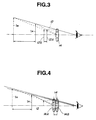
- Fig. 3 shows a principle of operation when the virtual image position adjusting knob 18 is rotated-to adjust the position of the virtual image.
- the LCDs 12 are positioned at a position 12A to the left of the aspherical lenses 14.
- the user can view a virtual image IA located at a position to the left of position 12A since the image displayed on the LCDs 12 is viewed via the aspherical lenses 14.
- the position of the aspherical lenses 14 is adjusted with respect to the LCDs 12 so that the position of the virtual image can be changed. That is to say, if the aspherical lenses 14 are placed at a position 14A to the right of LCDs 12, the user consequently views the virtual image IA located to the left of LCDs 12. On the contrary, when the aspherical lenses 14 are moved to the right of position 14A to a position 14B which is far away from the LCDs 12, the user can view the virtual image IB located to the left of virtual image IA at a position far away from the position 14B.
- the LCDs 12 are disposed toward a more inner position as compared with the case wherein the displayed position of the virtual image A is far away. In this way, the user can observe the virtual image A correctly even if the displayed position of the virtual image is far or near.
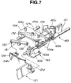
- Figs. 6 and 7 show specific structure examples to change the displayed position of a virtual image.
- An eccentric cam plate 162 is installed on the virtual image position adjusting knob 18 via an axle 161.
- the eccentric cam plate 162 is installed within the cam groove 132d of a slide plate 132.
- the slide plate 132 is moved forward or rearward (in Fig. 6, the left downward or right upward direction). This movement is guided by means of a pin 104c attached onto a frame 104 inserted into elongated grooved holes 132a and 132c formed on the slide plate 132.
- the LCDs 12 are held by LCD holders 124 and back light 11 and are mounted on a rear part of the slide plate 132. Therefore, since the virtual image position adjusting knob 18 is rotated, the LCDs 12 are finally moved toward the front position or toward a rear position (in Fig. 6, the left downward direction or right upper direction). That is to say, the LCDs 12 are moved toward or away from a unit main body 121 of an optical visual sensing unit 120 having the mirrors 13 and the aspherical lens 14. Thus, as shown in Fig. 3, the relative distance of the LCDs 12 to the aspherical lens 14 is changed so that the displayed position of the virtual image can be moved.
- pin portions 124c are extended on their bottom ends of the left and right LCD holders 124, respectively.
- the pin portions 124c are inserted into recessed portions 163c of the cam arm 163.
- the respective recessed portions 163c of the cam arm 163 arranged on its left and right sides are arranged such as an inverse U shape as viewed from above. Consequently, as the left and right LCD holders 124 are moved such as to be nearer to the unit main body 121, the left and right pin portions 124c are guided so as to be moved in the inner direction (mutually nearer direction).
- the left and right LCD holders 124 (hence, the LCDs 12 which are held thereon) are guided by means of a shaft 136 and moved in the inner direction (mutually nearer direction) since the holder's projection 124a is inserted into the shaft 136.
- the virtual image position adjusting knob 18 is adjusted so that the LCD holder 124 is moved in a direction such that the LCD holders 124 are separated from the unit main body 121, the left and right LCD holder 124 (left and right LCDs 12) are moved in mutually separated directions. Consequently, the convergence angle shown in Fig. 5 can be adjusted.
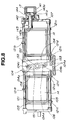
- Fig. 8 shows a specific example of the structure of the apparatus in order to adjust the relative distance between the left and right aspherical lenses 14 when the eye-width adjustment knob 17 is adjusted.
- the eye-width adjusting knob 17 is coupled to a cylindrical cam 141.
- the cylindrical cam 14 is rotatably held on the holder 107 of the aspherical lenses 14 by means of a stop ring 142.
- An outer periphery of the cylindrical cam 141 is formed with a cam grooved hole 141a.
- a cam pin 144 attached onto a head portion 143a of a rod 143 is inserted into a cam grooved hole 141a.
- a basic end portion 143b of the rod 143 is linked to the right sided aspherical lens 14.
- the cylindrical cam 141 is rotated integrally so that the cam pin 144 extended on the head portion 143a of the rod 143 is guided into the cam grooved hole 141a of the cylindrical cam 141.
- the cam pin 144 is moved in the leftward or rightward direction correspondingly to a rotational direction of the eye-width adjusting knob 17 as shown in Fig. 8. Consequently, the right side aspherical lens 14 to which the rod is linked is moved toward the left side or right side, their holding portions 121b and 121c being guided by means of the shaft 105.
- arms 154 are linked to inner sides of the left and right aspherical lenses 14 and their tips are formed with elongated grooved holes 154a, respectively.
- Pins 153 which are attached onto both ends of a pivotal lever 151 are inserted into the respective elongated grooved holes 154a. Then, a center of the pivotal lever 151 is pivotally supported on a fulcrum axle 152. Consequently, when the right side aspherical lens 14 is moved in the leftward direction as viewed from Fig. 8, arm 154 is moved accordingly toward the leftward direction. At this time, since the pin 153 inserted into the elongated grooved hole 154a of the arm 154 is pressed toward the leftward direction in Fig. 8, the pivotal lever 151 is pivoted in the clockwise direction with the fulcrum axle 152 as a fulcrum.
- the left and right aspherical lens 14 are moved in directions mutually separating, the left and right cam arms 163 are pivoted in the clockwise direction or counterclockwise direction with the pin portions 121d as a center, respectively, the left and right LCDs 12 are moved in directions mutually separating from each other, That is to say, they are adjusted so that the convergence angle becomes narrower.
- the relative distance between the aspherical lens 14 is not only adjusted but only the relative distance between the LCDs 12 is automatically adjusted so that the convergence angle can accordingly be adjusted.
- Fig. 9 shows an example of the virtual image position adjusting knob 18 having a mark 18A.
- symbols representing the position of the virtual image symbols such as 1 m, 3 m, and ⁇
- the user can adjust the position of the virtual image by rotating the adjusting knob 18 so that the mark 18A is aligned with a desired symbol. Consequently, the position of the virtual image can be adjusted.
- the position of the LCDs 12 is adjusted so that the displayed position of the virtual image indicates 1 m. If the mark 18A is made coincident to the position of the symbol 3 m or symbol ⁇ , the position of the LCDs 12 is adjusted so that the virtual image displayed position indicates the position denoted by 3 m or by ⁇ .
- Fig. 10 shows another example of the virtual image position adjusting knob 18.
- the position of the virtual image is not indicated in such direct distances as 1m, 3m, and ⁇ but indicated in the form of a magnitude of the image screen such as 50 inches, 40 inches, and 30 inches.
- the LCDs 12 are moved to a position at which the image screen of 50 inches can be observed by the user when, for example, the mark 18A of the virtual image position adjusting knob 18 is adjusted at a position of the symbol of 50 inches. If the mark 18A is adjusted to the symbol of 40 inches or 30 inches, the LCDs 12 are moved to a position equivalent to a case where the user views the image screen having the magnitude of 40 inches or 30 inches.
- these virtual image displayed positions can be displayed on the LCDs 12, as shown, for example, in Figs. 11 (a)-(c) and 12 (a)-(c).
- the symbols such as lm, 3m, and ⁇ in Fig. 9 are directly displayed on the LCDs 12 as shown in Figs. 11 (a) through 11 (c) so as to correspond to the rotated position of the virtual image position adjusting knob 18.
- numerals 50, 40, 30, and so forth each of which represent the magnitude of the image screen shown in Fig. 10 are displayed on the LCDs 12.
- numerals 50, 40, 30, and so forth each of which represent the magnitude of the image screen shown in Fig. 10 are displayed on the LCDs 12.
- a straight line with an arrow mark at both ends of the line is simultaneously displayed in a diagonal position on the image screen. If the user rotates the virtual image position adjusting knob 18, indications such as shown in Figs. 12 (a) through 12 (c) are consequently displayed on the LCDs 12 corresponding to the rotated position of the knob.
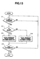
- Figs. 13 through 17 show embodiments for processing steps which occur in regard to the position of the virtual image.
- a CPU of the microcomputer of the control unit determines, at a step S1, whether a change in the displayed position of the virtual image is indicated. That is to say, the control unit 51 serves to monitor whether the virtual image position adjusting knob 18 has been operated. When the virtual image position adjusting knob 18 is operated, the routine goes from the step S1 to the step S2. At step S2, the CPU of the control unit determines whether the operation of the virtual image position adjusting knob 18 is carried out so as to direct the position of the virtual image far away from or nearer to the present position.
- the routine goes to a step S3 in which a predetermined speech message is output. That is to say, at this step, the control unit 51 controls the second acoustic generating unit 64 to generate, for example, messages such as "the image screen becomes smaller”, “displayed position becomes far away", or other similar messages.
- Such vocal messages as described above are output to the ear phone 31 via the first synthesize circuit 65 and D/A converter 66.
- the routine goes to a step S4 in which another vocal message corresponding to this operation is generated.
- the control unit 51 ultimately causes the generation of vocal messages such as "the image screen becomes larger", “the displayed position becomes closer” which are then output to the ear phone 31.
- each vocal message for each change in the virtual image displayed position is output so that the user can be more frequently alerted to the possibility of the occurrence of a minor discomfort.
- step S3 or step S4 where the predetermined message is output, the routine goes to step S5 where it is determined whether further processing is desired. If no instruction to end processing is input, the routine returns to the step S1 and processing is executed repeatedly.
- the CPU determines whether the displayed position of the virtual image is changed. If the CPU determines that the displayed position of the virtual image is changed, the routine goes to a step S12 wherein a message is issued which notifies the user of the possibility that a minor discomfort may occur. That is to say, at step S12, the control unit 51 controls the second acoustic generating unit 64 so that the vocal message is generated, for example, such as a vocal message indicating that long term use may cause a minor discomfort to occur. This vocal message is output to the earphone 31 via first the synthesize circuit 65 and D/A converter 66.
- the message generating unit 76 is controlled so that a similar message is generated in the form of characters. These characters are displayed on the LCDs 12 via the fourth synthesize circuit 85. It noted that either the vocal warning message or the video warning message may be selected and generated.
- a direct notification of the possibility that a minor discomfort may occur is not merely an indirect message but rather is in the form of either an audio or video message to ensure that the message is received and recognized by the user.
- step S11 the CPU determines whether the displayed position of the virtual image is changed, it is also possible to determine whether a predetermined time has elapsed upon the start of use of the eyeglass display 86. In this manner, it is possible to notify the user to the possibility that a minor discomfort may occur whenever a predetermined time period has passed. In particular, it has been found that when used for a two hour time period at a convergence angle of approximately 30, there is a substantially reduced possibility of the occurrence of a minor discomfort.
- the CPU waits for the instruction to change the displayed position of the virtual image. If the instruction to change the displayed position of the virtual image is issued, the routine goes to a step S22 in which the CPU determines whether this change in the displayed position is such a change that the convergence angle is directed to become wider or to become narrower. If the change is such that the convergence angle becomes wider, the routine goes to step S23 in which a predetermined notification of the possibility that a minor discomfort may occur is issued. For example, a warning that long term use might cause the occurrence of a minor discomfort may be output to either the ear phone 31 or the LCDs 12.
- step S22 the CPU determines whether the change is such a change that the convergence angle becomes narrower
- the routine goes to a step S24 in which a different notification from that in the step S23 is generated. For example, a warning such as "please avoid long term use if possible" may be output to either the ear phone 31 or LCDs 12.
- Fig. 16 shows a further embodiment of the present invention.
- the CPU determines whether the displayed position of the virtual image is changed. If the displayed position of the virtual image is changed due to the operation of the virtual displayed position adjusting knob 18, the routine goes from step S31 to step S32 in which the CPU determines whether this change makes the convergence angle wider or narrower than a predetermined reference angle value. If the convergence angle is wider than the predetermined reference value, the routine advances a step S33 in which a flag FA is set to 1 and a timer built in the control unit 51 is actuated. Thereafter, the routine returns from step S35 to step S31 in which the CPU again determines whether a change in the displayed position of the virtual image occurs.
- step S36 the routine determines whether the flag FA is set to 1. In this case, at step S33, the CPU determines that the flag FA is set to 1. Hence, in this case, the routine goes to step S37 in which the CPU determines whether the timer started at the step S33 has indicated a predetermined constant time.
- step S37 If the timer, at step S37, has determined that it is not yet passed the set time previously set by the timer, the routine returns to step S35 at which point it is determined whether a processing end has been instructed. If the end of processing has not yet been instructed, the routine again returns to step S31 and the same processing is repeated.
- step S37 the routine goes from step S37 to step S38 in which an automatic change message is output.
- an automatic change message For example, such a message as "the virtual image displayed position is made far way" is output to at least either of the ear phone 31 and the LCDs 12.
- the routine goes to a step S39 in which flag FA is reset and the LCDs 12 are forcefully (automatically) moved so that the virtual image position becomes further from the reference value so that the convergence angle becomes narrower than the reference value. That is to say, at this time, the control unit 51 drives a motor 56 included in the eyeglass display 86 to automatically move the LCDs 12 to a predetermined position. Consequently, in a case where the virtual image displayed position is nearer to the reference value (in a case where the convergence angle is wider than the previously set reference value), the term of use at the displayed position of the virtual image is limited within the previously set constant time. If more time is used than the set time, the displayed position of the virtual image is automatically moved toward a far-away position. Hence, the possibility of an occurrence of a minor discomfort is substantially reduced or eliminated.
- step S39 The routine then advances from step S39 to step S35 and returns again to step S31 if no instruction to end the processing is issued. Thereafter, the series of processing is executed repeatedly.
- step S32 In a case where the CPU determines that the convergence angle does not exceed the reference value at the step S32, the routine goes from step S32 to step S34 in which the user is notified of the possibility of the occurrence of a minor discomfort. That is to say, a message such as "long term use might generate a minor discomfort" is output. Then, at step S35, if the end of processing instruction is not given, the routine again returns to step S31 and the same series of processing is executed repeatedly.
- step S31 If the virtual image position adjusting knob 18 is not operated, the routine goes from step S31 to step S36. Since the flag FA is now reset, the routine again returns to the step S31. Thereafter, the series of processing steps are executed repeatedly.
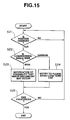
- Fig. 17 shows a still further embodiment.
- the same series of processing steps are executed as steps of S31 through S37 in Fig. 16, except that the processing at steps S58 and S59 is different from the processing at steps S38 and S39 in Fig. 16, respectively.
- the predetermined message is output so that the displayed state is automatically changed to reduce the convergence angle.
- the power supply is turned off
- the power supply is automatically turned off and the display is halted and the flag FA is reset. In this way, the possibility of an occurrence of a minor discomfort may be reduced or eliminated.
Landscapes
- Physics & Mathematics (AREA)
- General Physics & Mathematics (AREA)
- Optics & Photonics (AREA)
- Engineering & Computer Science (AREA)
- Multimedia (AREA)
- Signal Processing (AREA)
- Liquid Crystal (AREA)
- Controls And Circuits For Display Device (AREA)
Applications Claiming Priority (3)
| Application Number | Priority Date | Filing Date | Title |
|---|---|---|---|
| JP22840093A JP3322283B2 (ja) | 1993-09-14 | 1993-09-14 | 画像表示装置 |
| JP228400/93 | 1993-09-14 | ||
| JP22840093 | 1993-09-14 |
Publications (3)
| Publication Number | Publication Date |
|---|---|
| EP0643314A2 true EP0643314A2 (de) | 1995-03-15 |
| EP0643314A3 EP0643314A3 (de) | 1995-11-02 |
| EP0643314B1 EP0643314B1 (de) | 2000-03-01 |
Family
ID=16875878
Family Applications (1)
| Application Number | Title | Priority Date | Filing Date |
|---|---|---|---|
| EP94306701A Expired - Lifetime EP0643314B1 (de) | 1993-09-14 | 1994-09-13 | Vorrichtung zum Anzeigen von Bildern |
Country Status (5)
| Country | Link |
|---|---|
| US (1) | US5451976A (de) |
| EP (1) | EP0643314B1 (de) |
| JP (1) | JP3322283B2 (de) |
| KR (1) | KR100280860B1 (de) |
| DE (1) | DE69423162T2 (de) |
Cited By (24)
| Publication number | Priority date | Publication date | Assignee | Title |
|---|---|---|---|---|
| GB2295938A (en) * | 1994-12-09 | 1996-06-12 | Sega Enterprises Kk | Head mounted display |
| US5742373A (en) * | 1995-10-13 | 1998-04-21 | Massachusetts Institute Of Technology | Color microdisplays and methods of manufacturing same |
| WO1998029775A1 (en) * | 1997-01-02 | 1998-07-09 | Giora Kutz | A personal head mounted display device |
| US5867134A (en) * | 1995-08-25 | 1999-02-02 | Alvelda; Phillip | VLSI visual display |
| GB2337681A (en) * | 1994-12-09 | 1999-11-24 | Sega Enterprises Kk | A head mounted display |
| EP0660154B1 (de) * | 1993-12-22 | 2000-03-08 | Canon Kabushiki Kaisha | Anzeigevorrichtung für Mehrfachbilder |
| US6712480B1 (en) | 2002-09-27 | 2004-03-30 | Silicon Light Machines | Controlled curvature of stressed micro-structures |
| US6767751B2 (en) | 2002-05-28 | 2004-07-27 | Silicon Light Machines, Inc. | Integrated driver process flow |
| US6782205B2 (en) | 2001-06-25 | 2004-08-24 | Silicon Light Machines | Method and apparatus for dynamic equalization in wavelength division multiplexing |
| US6785001B2 (en) | 2001-08-21 | 2004-08-31 | Silicon Light Machines, Inc. | Method and apparatus for measuring wavelength jitter of light signal |
| US6800238B1 (en) | 2002-01-15 | 2004-10-05 | Silicon Light Machines, Inc. | Method for domain patterning in low coercive field ferroelectrics |
| US6801354B1 (en) | 2002-08-20 | 2004-10-05 | Silicon Light Machines, Inc. | 2-D diffraction grating for substantially eliminating polarization dependent losses |
| US6806997B1 (en) | 2003-02-28 | 2004-10-19 | Silicon Light Machines, Inc. | Patterned diffractive light modulator ribbon for PDL reduction |
| US6813059B2 (en) | 2002-06-28 | 2004-11-02 | Silicon Light Machines, Inc. | Reduced formation of asperities in contact micro-structures |
| US6822797B1 (en) | 2002-05-31 | 2004-11-23 | Silicon Light Machines, Inc. | Light modulator structure for producing high-contrast operation using zero-order light |
| US6829077B1 (en) | 2003-02-28 | 2004-12-07 | Silicon Light Machines, Inc. | Diffractive light modulator with dynamically rotatable diffraction plane |
| US6829092B2 (en) | 2001-08-15 | 2004-12-07 | Silicon Light Machines, Inc. | Blazed grating light valve |
| US6839479B2 (en) | 2002-05-29 | 2005-01-04 | Silicon Light Machines Corporation | Optical switch |
| EP1619903A1 (de) * | 2003-04-17 | 2006-01-25 | Sony Corporation | Bildverarbeitungseinrichtung für dreidimensionale ansichten, bildbereitstellungsverfahren für dreidimensionale ansichten und bildanzeigeverfahren |
| US7046420B1 (en) | 2003-02-28 | 2006-05-16 | Silicon Light Machines Corporation | MEM micro-structures and methods of making the same |
| EP2182402A1 (de) * | 2008-10-30 | 2010-05-05 | Honeywell International Inc. | Verfahren und System zum Betrieb eines Near-to-Eye-Displays |
| EP2472304A3 (de) * | 2010-12-29 | 2012-08-22 | Sony Corporation | Auf einem Kopf montierte Anzeige |
| US9641826B1 (en) | 2011-10-06 | 2017-05-02 | Evans & Sutherland Computer Corporation | System and method for displaying distant 3-D stereo on a dome surface |
| US20220326445A1 (en) * | 2021-04-13 | 2022-10-13 | Aether Optics, Llc | Optical Bridge |
Families Citing this family (45)
| Publication number | Priority date | Publication date | Assignee | Title |
|---|---|---|---|---|
| US5303085A (en) | 1992-02-07 | 1994-04-12 | Rallison Richard D | Optically corrected helmet mounted display |
| US5864326A (en) | 1992-02-07 | 1999-01-26 | I-O Display Systems Llc | Depixelated visual display |
| US6097543A (en) | 1992-02-07 | 2000-08-01 | I-O Display Systems Llc | Personal visual display |
| US5526022A (en) | 1993-01-06 | 1996-06-11 | Virtual I/O, Inc. | Sourceless orientation sensor |
| US5991087A (en) | 1993-11-12 | 1999-11-23 | I-O Display System Llc | Non-orthogonal plate in a virtual reality or heads up display |
| US6160666A (en) | 1994-02-07 | 2000-12-12 | I-O Display Systems Llc | Personal visual display system |
| EP0908754A3 (de) * | 1994-04-21 | 2000-04-12 | Sega Enterprises, Ltd. | Am Kopf montierte Bildanzeigevorrichtung |
| US5903395A (en) | 1994-08-31 | 1999-05-11 | I-O Display Systems Llc | Personal visual display system |
| US5683297A (en) * | 1994-12-16 | 1997-11-04 | Raviv; Roni | Head mounted modular electronic game system |
| US5644323A (en) * | 1994-12-21 | 1997-07-01 | Siliscape, Inc. | Miniature synthesized virtual image electronic display |
| US5684497A (en) * | 1994-12-21 | 1997-11-04 | Siliscape, Inc. | Twice folded compound magnified virtual image electronic display |
| US5991085A (en) | 1995-04-21 | 1999-11-23 | I-O Display Systems Llc | Head-mounted personal visual display apparatus with image generator and holder |
| USD383455S (en) * | 1995-08-31 | 1997-09-09 | Virtual I/O, Inc. | Head mounted display with headtracker |
| US6069608A (en) * | 1996-12-03 | 2000-05-30 | Sony Corporation | Display device having perception image for improving depth perception of a virtual image |
| US6057966A (en) * | 1997-05-09 | 2000-05-02 | Via, Inc. | Body-carryable display devices and systems using E.G. coherent fiber optic conduit |
| JP2856207B1 (ja) * | 1997-09-10 | 1999-02-10 | 日本電気株式会社 | 画像位置調整装置及び画像位置調整プログラムを記録したコンピュータが読み取り可能な記録媒体 |
| US5903396A (en) | 1997-10-17 | 1999-05-11 | I/O Display Systems, Llc | Intensified visual display |
| JPH11265248A (ja) * | 1998-03-18 | 1999-09-28 | Sony Corp | 眼鏡型画像表示装置 |
| US6826041B2 (en) * | 2002-10-07 | 2004-11-30 | Sun Yu | Dynamic angle computer monitor |
| JP4609256B2 (ja) * | 2005-09-15 | 2011-01-12 | ソニー株式会社 | ヘッドマウントディスプレイ |
| US7891818B2 (en) | 2006-12-12 | 2011-02-22 | Evans & Sutherland Computer Corporation | System and method for aligning RGB light in a single modulator projector |
| US8832557B2 (en) | 2007-05-04 | 2014-09-09 | Apple Inc. | Adjusting media display in a personal display system based on perspective |
| US8605008B1 (en) * | 2007-05-04 | 2013-12-10 | Apple Inc. | Head-mounted display |
| CN101526671B (zh) * | 2008-03-06 | 2010-07-07 | 黄峰彪 | 防止用近眼显示器时产生不适反应的方法及近眼显示器 |
| US8358317B2 (en) | 2008-05-23 | 2013-01-22 | Evans & Sutherland Computer Corporation | System and method for displaying a planar image on a curved surface |
| US8702248B1 (en) | 2008-06-11 | 2014-04-22 | Evans & Sutherland Computer Corporation | Projection method for reducing interpixel gaps on a viewing surface |
| US8957835B2 (en) | 2008-09-30 | 2015-02-17 | Apple Inc. | Head-mounted display apparatus for retaining a portable electronic device with display |
| US8077378B1 (en) | 2008-11-12 | 2011-12-13 | Evans & Sutherland Computer Corporation | Calibration system and method for light modulation device |
| JP4863527B2 (ja) * | 2009-12-01 | 2012-01-25 | 稔 稲葉 | 立体映像撮像装置 |
| JP5402293B2 (ja) * | 2009-06-22 | 2014-01-29 | ソニー株式会社 | 頭部装着型ディスプレイ、及び、頭部装着型ディスプレイにおける画像表示方法 |
| US9326675B2 (en) * | 2009-12-24 | 2016-05-03 | Microsoft Technology Licensing, Llc | Virtual vision correction for video display |
| JP5499854B2 (ja) * | 2010-04-08 | 2014-05-21 | ソニー株式会社 | 頭部装着型ディスプレイにおける光学的位置調整方法 |
| KR20120051308A (ko) * | 2010-11-12 | 2012-05-22 | 삼성전자주식회사 | 3d 입체감을 개선하고 시청 피로를 저감하는 방법 및 장치 |
| US9638920B2 (en) * | 2013-04-15 | 2017-05-02 | Microsoft Technology Licensing, Llc | Torsional support for binocular display |
| WO2015030099A1 (ja) | 2013-08-30 | 2015-03-05 | ブラザー工業株式会社 | 画像表示装置及びヘッドマウントディスプレイ |
| US9696552B1 (en) * | 2014-01-10 | 2017-07-04 | Lockheed Martin Corporation | System and method for providing an augmented reality lightweight clip-on wearable device |
| US9696551B2 (en) * | 2014-08-13 | 2017-07-04 | Beijing Lenovo Software Ltd. | Information processing method and electronic device |
| JP6367166B2 (ja) * | 2015-09-01 | 2018-08-01 | 株式会社東芝 | 電子機器及び方法 |
| CN105955454A (zh) * | 2016-04-15 | 2016-09-21 | 北京小鸟看看科技有限公司 | 一种用于虚拟现实系统的防眩晕方法和装置 |
| WO2017190336A1 (zh) * | 2016-05-06 | 2017-11-09 | 深圳动三帝虚拟现实互动科技有限公司 | 虚拟现实眼镜 |
| US10071307B1 (en) | 2017-03-09 | 2018-09-11 | Tzumi Electronics LLC | Virtual reality headset with retractable earphones |
| JP6519959B2 (ja) * | 2017-03-22 | 2019-05-29 | カシオ計算機株式会社 | 操作処理装置、再生装置、操作処理方法およびプログラム |
| CN107807447B (zh) * | 2017-11-24 | 2019-09-03 | 歌尔科技有限公司 | 一种调节装置及头显设备 |
| US20220003989A1 (en) * | 2018-11-09 | 2022-01-06 | Sony Corporation | Virtual image display apparatus and virtual image display method |
| JPWO2022249520A1 (de) * | 2021-05-28 | 2022-12-01 |
Citations (3)
| Publication number | Priority date | Publication date | Assignee | Title |
|---|---|---|---|---|
| EP0344881A2 (de) * | 1988-05-31 | 1989-12-06 | Reflection Technology, Inc. | Persönliche Headup-Anzeige |
| US5106179A (en) * | 1990-05-17 | 1992-04-21 | Sony Corporation | Eyesight auxiliary liquid crystal device |
| EP0551781A1 (de) * | 1991-12-27 | 1993-07-21 | Sony Corporation | Brillenartige Bildanzeige-Vorrichtung |
Family Cites Families (30)
| Publication number | Priority date | Publication date | Assignee | Title |
|---|---|---|---|---|
| GB1044833A (en) * | 1961-10-23 | 1966-10-05 | Hedda Werthenmer | Cinematograph apparatus |
| US3787109A (en) * | 1972-06-28 | 1974-01-22 | Honeywell Inc | Inside helmet sight apparatus |
| US3923370A (en) * | 1974-10-15 | 1975-12-02 | Honeywell Inc | Head mounted displays |
| GB1540992A (en) * | 1975-04-22 | 1979-02-21 | Smiths Industries Ltd | Display or other systems and equipment for use in such systems |
| GB1533859A (en) * | 1975-04-29 | 1978-11-29 | Elliott Bros | Headgear incorporating optical display systems |
| GB1527049A (en) * | 1976-06-18 | 1978-10-04 | Pilkington Perkin Elmer Ltd | Head-up displays |
| US4257062A (en) * | 1978-12-29 | 1981-03-17 | Meredith Russell W | Personalized audio-visual system |
| US4310849A (en) * | 1979-06-11 | 1982-01-12 | Glass Stuart M | Stereoscopic video system |
| US4559555A (en) * | 1982-02-24 | 1985-12-17 | Arnold Schoolman | Stereoscopic remote viewing system |
| US4516157A (en) * | 1982-11-23 | 1985-05-07 | Campbell Malcolm G | Portable electronic camera |
| JPS59117876A (ja) * | 1982-12-24 | 1984-07-07 | Seiko Epson Corp | パ−ソナル液晶映像表示器 |
| US4706117A (en) * | 1984-06-01 | 1987-11-10 | Arnold Schoolman | Stereo laser disc viewing system |
| US5281957A (en) * | 1984-11-14 | 1994-01-25 | Schoolman Scientific Corp. | Portable computer and head mounted display |
| FR2593932B1 (fr) * | 1986-02-04 | 1989-12-01 | Thomson Csf | Dispositif de visualisation a grand champ et a rendement optique eleve |
| US4753514A (en) * | 1986-05-12 | 1988-06-28 | Iota Instrumentation Co. | Headwear-mounted periscopic display device |
| US4952024A (en) * | 1986-08-29 | 1990-08-28 | Gale Thomas S | Three-dimensional sight and sound reproduction apparatus for individual use |
| US4757714A (en) * | 1986-09-25 | 1988-07-19 | Insight, Inc. | Speed sensor and head-mounted data display |
| GB8701288D0 (en) * | 1987-01-21 | 1987-02-25 | Waldern J D | Perception of computer-generated imagery |
| US5097252A (en) * | 1987-03-24 | 1992-03-17 | Vpl Research Inc. | Motion sensor which produces an asymmetrical signal in response to symmetrical movement |
| GB8715184D0 (en) * | 1987-06-29 | 1987-10-21 | Gec Avionics | Stereoscopic presentation of data |
| US4751691A (en) * | 1987-07-01 | 1988-06-14 | Perera Kalukapuge T | Optical projection time-piece attachment for spectacles or combination thereof |
| US4806011A (en) * | 1987-07-06 | 1989-02-21 | Bettinger David S | Spectacle-mounted ocular display apparatus |
| US4805988A (en) * | 1987-07-24 | 1989-02-21 | Nelson Dones | Personal video viewing device |
| HU197469B (en) * | 1987-10-23 | 1989-03-28 | Laszlo Holakovszky | Spectacle like, wearable on head stereoscopic reproductor of the image |
| US4874235A (en) * | 1987-11-17 | 1989-10-17 | Webster John A | Stereoscopic viewing system and method |
| US4853764A (en) * | 1988-09-16 | 1989-08-01 | Pedalo, Inc. | Method and apparatus for screenless panoramic stereo TV system |
| US4933755A (en) * | 1989-02-15 | 1990-06-12 | Dahl Thomas R | Head mounted stereoscopic television viewer |
| JP3129719B2 (ja) * | 1989-04-21 | 2001-01-31 | 株式会社パルカ | ビデオディスプレイ装置 |
| US5355181A (en) * | 1990-08-20 | 1994-10-11 | Sony Corporation | Apparatus for direct display of an image on the retina of the eye using a scanning laser |
| US5347400A (en) * | 1993-05-06 | 1994-09-13 | Ken Hunter | Optical system for virtual reality helmet |
-
1993
- 1993-09-14 JP JP22840093A patent/JP3322283B2/ja not_active Expired - Fee Related
-
1994
- 1994-09-13 EP EP94306701A patent/EP0643314B1/de not_active Expired - Lifetime
- 1994-09-13 KR KR1019940022999A patent/KR100280860B1/ko not_active IP Right Cessation
- 1994-09-13 US US08/305,130 patent/US5451976A/en not_active Expired - Lifetime
- 1994-09-13 DE DE69423162T patent/DE69423162T2/de not_active Expired - Fee Related
Patent Citations (3)
| Publication number | Priority date | Publication date | Assignee | Title |
|---|---|---|---|---|
| EP0344881A2 (de) * | 1988-05-31 | 1989-12-06 | Reflection Technology, Inc. | Persönliche Headup-Anzeige |
| US5106179A (en) * | 1990-05-17 | 1992-04-21 | Sony Corporation | Eyesight auxiliary liquid crystal device |
| EP0551781A1 (de) * | 1991-12-27 | 1993-07-21 | Sony Corporation | Brillenartige Bildanzeige-Vorrichtung |
Non-Patent Citations (1)
| Title |
|---|
| OPTOELECTRONICS DEVICES AND TECHNOLOGIES, vol. 6, no. 1, June 1991 TOKYO JP, pages 155-162, XP 000245833 B. WELLS 'A miniature virtual display implement' * |
Cited By (34)
| Publication number | Priority date | Publication date | Assignee | Title |
|---|---|---|---|---|
| US6064353A (en) * | 1993-12-22 | 2000-05-16 | Canon Kabushiki Kaisha | Multi-eye image display apparatus |
| EP0660154B1 (de) * | 1993-12-22 | 2000-03-08 | Canon Kabushiki Kaisha | Anzeigevorrichtung für Mehrfachbilder |
| GB2337681B (en) * | 1994-12-09 | 2000-02-23 | Sega Enterprises Kk | Head mounted display and head mounted video display system |
| GB2295938A (en) * | 1994-12-09 | 1996-06-12 | Sega Enterprises Kk | Head mounted display |
| US5844530A (en) * | 1994-12-09 | 1998-12-01 | Kabushiki Kaisha Sega Enterprises | Head mounted display, and head mounted video display system |
| GB2337681A (en) * | 1994-12-09 | 1999-11-24 | Sega Enterprises Kk | A head mounted display |
| GB2295938B (en) * | 1994-12-09 | 2000-02-23 | Sega Enterprises Kk | Head mounted display, and head mounted video display system |
| US5867134A (en) * | 1995-08-25 | 1999-02-02 | Alvelda; Phillip | VLSI visual display |
| US6222508B1 (en) | 1995-08-25 | 2001-04-24 | Massachusetts Institute Of Technology | VLSI visual display |
| US5742373A (en) * | 1995-10-13 | 1998-04-21 | Massachusetts Institute Of Technology | Color microdisplays and methods of manufacturing same |
| WO1998029775A1 (en) * | 1997-01-02 | 1998-07-09 | Giora Kutz | A personal head mounted display device |
| US6782205B2 (en) | 2001-06-25 | 2004-08-24 | Silicon Light Machines | Method and apparatus for dynamic equalization in wavelength division multiplexing |
| US6829092B2 (en) | 2001-08-15 | 2004-12-07 | Silicon Light Machines, Inc. | Blazed grating light valve |
| US6785001B2 (en) | 2001-08-21 | 2004-08-31 | Silicon Light Machines, Inc. | Method and apparatus for measuring wavelength jitter of light signal |
| US6800238B1 (en) | 2002-01-15 | 2004-10-05 | Silicon Light Machines, Inc. | Method for domain patterning in low coercive field ferroelectrics |
| US6767751B2 (en) | 2002-05-28 | 2004-07-27 | Silicon Light Machines, Inc. | Integrated driver process flow |
| US6839479B2 (en) | 2002-05-29 | 2005-01-04 | Silicon Light Machines Corporation | Optical switch |
| US6822797B1 (en) | 2002-05-31 | 2004-11-23 | Silicon Light Machines, Inc. | Light modulator structure for producing high-contrast operation using zero-order light |
| US6813059B2 (en) | 2002-06-28 | 2004-11-02 | Silicon Light Machines, Inc. | Reduced formation of asperities in contact micro-structures |
| US6801354B1 (en) | 2002-08-20 | 2004-10-05 | Silicon Light Machines, Inc. | 2-D diffraction grating for substantially eliminating polarization dependent losses |
| US6712480B1 (en) | 2002-09-27 | 2004-03-30 | Silicon Light Machines | Controlled curvature of stressed micro-structures |
| US7046420B1 (en) | 2003-02-28 | 2006-05-16 | Silicon Light Machines Corporation | MEM micro-structures and methods of making the same |
| US6806997B1 (en) | 2003-02-28 | 2004-10-19 | Silicon Light Machines, Inc. | Patterned diffractive light modulator ribbon for PDL reduction |
| US6829077B1 (en) | 2003-02-28 | 2004-12-07 | Silicon Light Machines, Inc. | Diffractive light modulator with dynamically rotatable diffraction plane |
| EP1619903A4 (de) * | 2003-04-17 | 2010-09-15 | Sony Corp | Bildverarbeitungseinrichtung für dreidimensionale ansichten, bildbereitstellungsverfahren für dreidimensionale ansichten und bildanzeigeverfahren |
| EP1619903A1 (de) * | 2003-04-17 | 2006-01-25 | Sony Corporation | Bildverarbeitungseinrichtung für dreidimensionale ansichten, bildbereitstellungsverfahren für dreidimensionale ansichten und bildanzeigeverfahren |
| EP2182402A1 (de) * | 2008-10-30 | 2010-05-05 | Honeywell International Inc. | Verfahren und System zum Betrieb eines Near-to-Eye-Displays |
| US8963804B2 (en) | 2008-10-30 | 2015-02-24 | Honeywell International Inc. | Method and system for operating a near-to-eye display |
| EP2472304A3 (de) * | 2010-12-29 | 2012-08-22 | Sony Corporation | Auf einem Kopf montierte Anzeige |
| US9641826B1 (en) | 2011-10-06 | 2017-05-02 | Evans & Sutherland Computer Corporation | System and method for displaying distant 3-D stereo on a dome surface |
| US10110876B1 (en) | 2011-10-06 | 2018-10-23 | Evans & Sutherland Computer Corporation | System and method for displaying images in 3-D stereo |
| US20220326445A1 (en) * | 2021-04-13 | 2022-10-13 | Aether Optics, Llc | Optical Bridge |
| WO2022221350A1 (en) * | 2021-04-13 | 2022-10-20 | Aether Optics, Llc | Optical bridge |
| US12085763B2 (en) * | 2021-04-13 | 2024-09-10 | Aether Optics, Llc | Optical bridge |
Also Published As
| Publication number | Publication date |
|---|---|
| KR100280860B1 (ko) | 2001-02-01 |
| DE69423162D1 (de) | 2000-04-06 |
| JP3322283B2 (ja) | 2002-09-09 |
| KR950010551A (ko) | 1995-04-28 |
| JPH0784234A (ja) | 1995-03-31 |
| EP0643314B1 (de) | 2000-03-01 |
| US5451976A (en) | 1995-09-19 |
| DE69423162T2 (de) | 2000-07-06 |
| EP0643314A3 (de) | 1995-11-02 |
Similar Documents
| Publication | Publication Date | Title |
|---|---|---|
| US5451976A (en) | Image display apparatus | |
| US7173765B2 (en) | Information display system | |
| US7593757B2 (en) | Mobile information apparatus | |
| EP0539907B1 (de) | Am Kopf befestigte Abbildungsvorrichtung | |
| US6005536A (en) | Captioning glasses | |
| US20060017657A1 (en) | Information display system | |
| EP1720058A1 (de) | Bildanzeigeeinrichtung | |
| WO2008032854A1 (fr) | Unité d'affichage montable sur lunettes et unité d'affichage d'image | |
| JPH0836143A (ja) | ヘッドマウントディスプレイ装置 | |
| CN108196629A (zh) | 显示设备 | |
| JP2003279883A (ja) | 表示装置付き帽子 | |
| KR101983450B1 (ko) | 플로팅 홀로그램 디스플레이 장치 및 이를 포함하는 스피커 | |
| JP2001154637A (ja) | 頭部装着型表示装置 | |
| JP2005321479A (ja) | 頭部装着型表示装置 | |
| CN113514954B (zh) | 一种基于激光光束扫描的智能眼镜 | |
| JPH05304646A (ja) | 映像表示装置 | |
| WO2011058707A1 (ja) | 撮影装置および遠隔作業支援システム | |
| WO2004053564A2 (en) | Face-mounted apparatus having spectacles and a video display integrated into the spectacles | |
| JP4258950B2 (ja) | 映像表示装置 | |
| JP2005195822A (ja) | 画像表示装置 | |
| JP4366526B2 (ja) | 視力回復トレーニング装置 | |
| JP2004236241A (ja) | 表示装置 | |
| CN207976793U (zh) | 显示设备 | |
| JP2000041204A (ja) | ヘッドマウント型映像表示装置 | |
| GB2337681A (en) | A head mounted display |
Legal Events
| Date | Code | Title | Description |
|---|---|---|---|
| PUAI | Public reference made under article 153(3) epc to a published international application that has entered the european phase |
Free format text: ORIGINAL CODE: 0009012 |
|
| AK | Designated contracting states |
Kind code of ref document: A2 Designated state(s): DE FR GB |
|
| PUAL | Search report despatched |
Free format text: ORIGINAL CODE: 0009013 |
|
| AK | Designated contracting states |
Kind code of ref document: A3 Designated state(s): DE FR GB |
|
| 17P | Request for examination filed |
Effective date: 19960319 |
|
| 17Q | First examination report despatched |
Effective date: 19960524 |
|
| GRAG | Despatch of communication of intention to grant |
Free format text: ORIGINAL CODE: EPIDOS AGRA |
|
| GRAG | Despatch of communication of intention to grant |
Free format text: ORIGINAL CODE: EPIDOS AGRA |
|
| GRAG | Despatch of communication of intention to grant |
Free format text: ORIGINAL CODE: EPIDOS AGRA |
|
| GRAG | Despatch of communication of intention to grant |
Free format text: ORIGINAL CODE: EPIDOS AGRA |
|
| GRAH | Despatch of communication of intention to grant a patent |
Free format text: ORIGINAL CODE: EPIDOS IGRA |
|
| GRAH | Despatch of communication of intention to grant a patent |
Free format text: ORIGINAL CODE: EPIDOS IGRA |
|
| GRAA | (expected) grant |
Free format text: ORIGINAL CODE: 0009210 |
|
| AK | Designated contracting states |
Kind code of ref document: B1 Designated state(s): DE FR GB |
|
| REF | Corresponds to: |
Ref document number: 69423162 Country of ref document: DE Date of ref document: 20000406 |
|
| ET | Fr: translation filed | ||
| PLBE | No opposition filed within time limit |
Free format text: ORIGINAL CODE: 0009261 |
|
| STAA | Information on the status of an ep patent application or granted ep patent |
Free format text: STATUS: NO OPPOSITION FILED WITHIN TIME LIMIT |
|
| 26N | No opposition filed | ||
| PGFP | Annual fee paid to national office [announced via postgrant information from national office to epo] |
Ref country code: FR Payment date: 20010911 Year of fee payment: 8 |
|
| PGFP | Annual fee paid to national office [announced via postgrant information from national office to epo] |
Ref country code: GB Payment date: 20010912 Year of fee payment: 8 |
|
| PGFP | Annual fee paid to national office [announced via postgrant information from national office to epo] |
Ref country code: DE Payment date: 20011001 Year of fee payment: 8 |
|
| REG | Reference to a national code |
Ref country code: GB Ref legal event code: IF02 |
|
| PG25 | Lapsed in a contracting state [announced via postgrant information from national office to epo] |
Ref country code: GB Free format text: LAPSE BECAUSE OF NON-PAYMENT OF DUE FEES Effective date: 20020913 |
|
| PG25 | Lapsed in a contracting state [announced via postgrant information from national office to epo] |
Ref country code: DE Free format text: LAPSE BECAUSE OF NON-PAYMENT OF DUE FEES Effective date: 20030401 |
|
| GBPC | Gb: european patent ceased through non-payment of renewal fee |
Effective date: 20020913 |
|
| PG25 | Lapsed in a contracting state [announced via postgrant information from national office to epo] |
Ref country code: FR Free format text: LAPSE BECAUSE OF NON-PAYMENT OF DUE FEES Effective date: 20030603 |
|
| REG | Reference to a national code |
Ref country code: FR Ref legal event code: ST |