EP0638445B2 - Pneumatique à carcasse radiale - Google Patents
Pneumatique à carcasse radiale Download PDFInfo
- Publication number
- EP0638445B2 EP0638445B2 EP94305876A EP94305876A EP0638445B2 EP 0638445 B2 EP0638445 B2 EP 0638445B2 EP 94305876 A EP94305876 A EP 94305876A EP 94305876 A EP94305876 A EP 94305876A EP 0638445 B2 EP0638445 B2 EP 0638445B2
- Authority
- EP
- European Patent Office
- Prior art keywords
- bead
- tyre
- carcass
- portions
- cords
- Prior art date
- Legal status (The legal status is an assumption and is not a legal conclusion. Google has not performed a legal analysis and makes no representation as to the accuracy of the status listed.)
- Expired - Lifetime
Links
- 239000011324 bead Substances 0.000 claims abstract description 134
- 125000006850 spacer group Chemical group 0.000 claims abstract description 65
- 239000000463 material Substances 0.000 claims description 7
- 238000005452 bending Methods 0.000 description 11
- 239000000835 fiber Substances 0.000 description 6
- 239000012141 concentrate Substances 0.000 description 4
- 238000010276 construction Methods 0.000 description 2
- 230000003247 decreasing effect Effects 0.000 description 2
- 239000000203 mixture Substances 0.000 description 2
- 230000007935 neutral effect Effects 0.000 description 2
- 229920000728 polyester Polymers 0.000 description 2
- 229920001875 Ebonite Polymers 0.000 description 1
- 239000004677 Nylon Substances 0.000 description 1
- 229910000831 Steel Inorganic materials 0.000 description 1
- 239000004760 aramid Substances 0.000 description 1
- 229920003235 aromatic polyamide Polymers 0.000 description 1
- 230000008094 contradictory effect Effects 0.000 description 1
- 239000000446 fuel Substances 0.000 description 1
- 238000007689 inspection Methods 0.000 description 1
- 229920001778 nylon Polymers 0.000 description 1
- 238000000926 separation method Methods 0.000 description 1
- 239000010959 steel Substances 0.000 description 1
- 239000013585 weight reducing agent Substances 0.000 description 1
Images


Classifications
-
- B—PERFORMING OPERATIONS; TRANSPORTING
- B60—VEHICLES IN GENERAL
- B60C—VEHICLE TYRES; TYRE INFLATION; TYRE CHANGING; CONNECTING VALVES TO INFLATABLE ELASTIC BODIES IN GENERAL; DEVICES OR ARRANGEMENTS RELATED TO TYRES
- B60C15/00—Tyre beads, e.g. ply turn-up or overlap
- B60C15/0009—Tyre beads, e.g. ply turn-up or overlap features of the carcass terminal portion
- B60C15/0036—Tyre beads, e.g. ply turn-up or overlap features of the carcass terminal portion with high ply turn-up, i.e. folded around the bead core and terminating radially above the point of maximum section width
- B60C15/0045—Tyre beads, e.g. ply turn-up or overlap features of the carcass terminal portion with high ply turn-up, i.e. folded around the bead core and terminating radially above the point of maximum section width with ply turn-up up to the belt edges, i.e. folded around the bead core and extending to the belt edges
-
- B—PERFORMING OPERATIONS; TRANSPORTING
- B60—VEHICLES IN GENERAL
- B60C—VEHICLE TYRES; TYRE INFLATION; TYRE CHANGING; CONNECTING VALVES TO INFLATABLE ELASTIC BODIES IN GENERAL; DEVICES OR ARRANGEMENTS RELATED TO TYRES
- B60C13/00—Tyre sidewalls; Protecting, decorating, marking, or the like, thereof
-
- B—PERFORMING OPERATIONS; TRANSPORTING
- B60—VEHICLES IN GENERAL
- B60C—VEHICLE TYRES; TYRE INFLATION; TYRE CHANGING; CONNECTING VALVES TO INFLATABLE ELASTIC BODIES IN GENERAL; DEVICES OR ARRANGEMENTS RELATED TO TYRES
- B60C15/00—Tyre beads, e.g. ply turn-up or overlap
- B60C15/0009—Tyre beads, e.g. ply turn-up or overlap features of the carcass terminal portion
- B60C15/0036—Tyre beads, e.g. ply turn-up or overlap features of the carcass terminal portion with high ply turn-up, i.e. folded around the bead core and terminating radially above the point of maximum section width
-
- B—PERFORMING OPERATIONS; TRANSPORTING
- B60—VEHICLES IN GENERAL
- B60C—VEHICLE TYRES; TYRE INFLATION; TYRE CHANGING; CONNECTING VALVES TO INFLATABLE ELASTIC BODIES IN GENERAL; DEVICES OR ARRANGEMENTS RELATED TO TYRES
- B60C17/00—Tyres characterised by means enabling restricted operation in damaged or deflated condition; Accessories therefor
- B60C17/0009—Tyres characterised by means enabling restricted operation in damaged or deflated condition; Accessories therefor comprising sidewall rubber inserts, e.g. crescent shaped inserts
-
- B—PERFORMING OPERATIONS; TRANSPORTING
- B60—VEHICLES IN GENERAL
- B60C—VEHICLE TYRES; TYRE INFLATION; TYRE CHANGING; CONNECTING VALVES TO INFLATABLE ELASTIC BODIES IN GENERAL; DEVICES OR ARRANGEMENTS RELATED TO TYRES
- B60C9/00—Reinforcements or ply arrangement of pneumatic tyres
- B60C9/02—Carcasses
- B60C9/04—Carcasses the reinforcing cords of each carcass ply arranged in a substantially parallel relationship
- B60C9/08—Carcasses the reinforcing cords of each carcass ply arranged in a substantially parallel relationship the cords extend transversely from bead to bead, i.e. radial ply
-
- B—PERFORMING OPERATIONS; TRANSPORTING
- B60—VEHICLES IN GENERAL
- B60C—VEHICLE TYRES; TYRE INFLATION; TYRE CHANGING; CONNECTING VALVES TO INFLATABLE ELASTIC BODIES IN GENERAL; DEVICES OR ARRANGEMENTS RELATED TO TYRES
- B60C9/00—Reinforcements or ply arrangement of pneumatic tyres
- B60C9/02—Carcasses
- B60C9/14—Carcasses built-up with sheets, webs, or films of homogeneous material, e.g. synthetics, sheet metal, rubber
-
- B—PERFORMING OPERATIONS; TRANSPORTING
- B60—VEHICLES IN GENERAL
- B60C—VEHICLE TYRES; TYRE INFLATION; TYRE CHANGING; CONNECTING VALVES TO INFLATABLE ELASTIC BODIES IN GENERAL; DEVICES OR ARRANGEMENTS RELATED TO TYRES
- B60C15/00—Tyre beads, e.g. ply turn-up or overlap
- B60C15/06—Flipper strips, fillers, or chafing strips and reinforcing layers for the construction of the bead
- B60C2015/0617—Flipper strips, fillers, or chafing strips and reinforcing layers for the construction of the bead comprising a cushion rubber other than the chafer or clinch rubber
- B60C2015/0621—Flipper strips, fillers, or chafing strips and reinforcing layers for the construction of the bead comprising a cushion rubber other than the chafer or clinch rubber adjacent to the carcass turnup portion
-
- Y—GENERAL TAGGING OF NEW TECHNOLOGICAL DEVELOPMENTS; GENERAL TAGGING OF CROSS-SECTIONAL TECHNOLOGIES SPANNING OVER SEVERAL SECTIONS OF THE IPC; TECHNICAL SUBJECTS COVERED BY FORMER USPC CROSS-REFERENCE ART COLLECTIONS [XRACs] AND DIGESTS
- Y10—TECHNICAL SUBJECTS COVERED BY FORMER USPC
- Y10T—TECHNICAL SUBJECTS COVERED BY FORMER US CLASSIFICATION
- Y10T152/00—Resilient tires and wheels
- Y10T152/10—Tires, resilient
- Y10T152/10495—Pneumatic tire or inner tube
- Y10T152/10819—Characterized by the structure of the bead portion of the tire
- Y10T152/10837—Bead characterized by the radial extent of apex, flipper or chafer into tire sidewall
-
- Y—GENERAL TAGGING OF NEW TECHNOLOGICAL DEVELOPMENTS; GENERAL TAGGING OF CROSS-SECTIONAL TECHNOLOGIES SPANNING OVER SEVERAL SECTIONS OF THE IPC; TECHNICAL SUBJECTS COVERED BY FORMER USPC CROSS-REFERENCE ART COLLECTIONS [XRACs] AND DIGESTS
- Y10—TECHNICAL SUBJECTS COVERED BY FORMER USPC
- Y10T—TECHNICAL SUBJECTS COVERED BY FORMER US CLASSIFICATION
- Y10T152/00—Resilient tires and wheels
- Y10T152/10—Tires, resilient
- Y10T152/10495—Pneumatic tire or inner tube
- Y10T152/10819—Characterized by the structure of the bead portion of the tire
- Y10T152/10846—Bead characterized by the chemical composition and or physical properties of elastomers or the like
-
- Y—GENERAL TAGGING OF NEW TECHNOLOGICAL DEVELOPMENTS; GENERAL TAGGING OF CROSS-SECTIONAL TECHNOLOGIES SPANNING OVER SEVERAL SECTIONS OF THE IPC; TECHNICAL SUBJECTS COVERED BY FORMER USPC CROSS-REFERENCE ART COLLECTIONS [XRACs] AND DIGESTS
- Y10—TECHNICAL SUBJECTS COVERED BY FORMER USPC
- Y10T—TECHNICAL SUBJECTS COVERED BY FORMER US CLASSIFICATION
- Y10T152/00—Resilient tires and wheels
- Y10T152/10—Tires, resilient
- Y10T152/10495—Pneumatic tire or inner tube
- Y10T152/10855—Characterized by the carcass, carcass material, or physical arrangement of the carcass materials
- Y10T152/10864—Sidewall stiffening or reinforcing means other than main carcass plies or foldups thereof about beads
Definitions
- the present invention relates to a pneumatic radial passenger car tyre as specified in the preambles of the independent claims and having an improved carcass structure, in which steering performances are improved without increasing the tyre weight.
- a pneumatic radial tyre especially a passenger radial tyre is provided with a carcass made of one or two plies of radially arranged cords.
- the ply In the case of one carcass ply, usually, the ply is turned up around bead the cores from the inside to the outside of the tyre to be secured thereto.
- both of them are turned up around bead cores, or 2) one of them is turned up around the bead cores and the other is turned down around the bead cores from the axially outside.
- the tyre sidewall portions are provided with rigidity so as to increase the lateral stiffness of the tyre to obtain the desired steering performance.
- a tyre for a motorcycle having a rubber spacer inserted in the sidewall is known from US-A-4770222.
- the carcass cord angles are specifically limited in the range of 50 to 65 degrees and thus the tyre is not a radial tyre.
- EP-A-0535938 shows a tyre in accordance with the preambles of the independent claims. This document discloses a cord spacing in the range from 1 to 10 times the diameter of the cords, in particular the value 4.4.
- an object of the present invention to provide a pneumatic radial tyre in which steering performances are improved, without increasing the tyre weight.
- the upper sidewall region between the axially outer edge of the belt and the maximum tyre width position is subjected to a large bending deformation during running. By increasing the rigidity of this region, the bending deformation is controlled, and steering performances can be effectively improved.
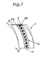
- a bending stress neutral line (X) in the above-mentioned region lies within the thickness of the carcass as shown in Fig.6. Accordingly, in a conventional carcass structure in which carcass cord plies A and B directly abut each other, resistance against the bending stress is mainly given by the bending rigidity of the cords.
- the carcass cords are located at a distance from the bending stress neutral line X as shown in Fig.7.
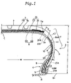
- pneumatic radial tyres 1 are formed as a low aspect ratio passenger radial tyre which has an aspect ratio H/W (tyre section height H / tyre maximum width W) of not more than 0.60.
- the tyre 1 is shown mounted on a standard rim R and inflated to its regular inner pressure.
- the tyre 1 comprises a tread portion 2, a pair of sidewall portions 3 each extending radially inwardly from each edge of the tread portion 2, and a bead portion 4 positioned at the radially inner end of each of the sidewall portions 3.
- the tyre 1 further comprises a carcass 6 extending between the bead portions 4 and 4, and a stiff belt 7 disposed radially outside the carcass 6 and inside the tread portion 2.
- the carcass comprises at least one ply of organic fibre cords 22, e.g. polyester fibre cords or the like.
- the carcass cords 22 are arranged at an angle of 70 to 90 degrees with respect to the tyre equator C and rubberised with a topping rubber 12.
- Each of the bead portions 4 is provided with a bead core 5 and a bead apex 8.
- the bead apex 8 is made of hard rubber and is tapered radially outwardly from the bead core 5.
- the hardness of the bead apex rubber is 83 to 97 degrees Shore A (80 to 95 degrees JIS A), and the complex elastic modulus E* thereof is preferably 300 to 600 kgf/cm 2 .
- the height HB of the bead apex 8 from the bead base line BL is preferably not more than 0.50 times, for example 0.48 times, the tyre section height H.
- the belt 7 comprises at least two crossed plies of parallel cords laid at a small angle of not more than 30 degrees with respect to the tyre equator C.
- high modulus cords e.g. steel cords, aromatic polyamide fibre cords or the like.
- the belt 7 consists of two crossed plies 7A and 7B and a band 25 disposed radially outside the cross plies.
- the band 25 is made of organic fibre cords, preferably nylon cords, laid substantially parallel to the circumferential direction of the tyre.
- the band 25 comprises at least one wide ply 23 extending over the full width of the cross plies and disposed on the radially outside of the outer ply 7A.
- the band 25 can include a pair of axially spaced narrow edge plies 24 disposed in the edge portions of the belt 7 as shown in Fig.1.
- the band 25 can include two wide plies, without narrow edge plies.
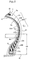
- Figs.1-3 show the first embodiment in which the carcass 6 comprises an inner ply 6A and an outer ply 6B.
- Each ply 6A,6B consists of a main portion 20A,20B and a pair of turnup portions 21A,21B.
- the main portions (20A,20B) extend between the bead cores 5 through the tread portion 2 and sidewall portions 3, and each turnup portion 21 is turned up around each bead core 5 from the inside to outside of the tyre.
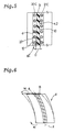
- Each carcass ply 6A and 6B is made of organic fibre cords 22, e.g. polyester fibre cords or the like, arranged at an angle of 70 to 90 degrees with respect to the tyre equator C and rubberised with a topping rubber 12, as shown in Fig.3.
- organic fibre cords 22 e.g. polyester fibre cords or the like
- the end 6Be of the turnup portion 21B of the outer carcass ply 6B is terminated at the axially outer side face of the bead apex 8 to avoid a concentration of bending stress.
- the turnup portion 21A of the inner carcass ply 6A covers the above-mentioned edge 6Be of the turnup portion 21B.
- the end 6Ae of the turnup portion 21A is terminated at a position radially outwards of both the upper end of the bead apex 8 and the maximum tyre width position P.
- the end 6Ae is located within the region Y defined between the maximum width position P and the axially outer edge 7e of the belt 7.
- the turnup portion 21A can be extended radially outwardly so that the end 6Ae thereof is secured between the belt 7 and the carcass ply main portion.
- a rubber spacer 9 is disposed between the two carcass ply main portions 20A and 20B so as to form a spaced portion 10.
- the rubber spacer 9 is a sheet of rubber.
- the radially inner and outer edge portions thereof are tapered, and the remaining portion therebetween has a substantially constant thickness.
- the thickness may be increased gradually from the edges to the centre thereof so that the central portion is thickest.
- the width of the tapered portion is about 3 times the cord spacing D.
- the mean cord spacing D between the carcass cords 22 in the inner carcass ply main portion 20A and the carcass cords 22 in the outer carcass ply main portion 20B is in the range of from 0.55 to 5.5 times the diameter (d) of the carcass cords 22.
- This spaced portion 10 increases the bending rigidity of this region Y, in which the bending deformation is largest, and steering performances can be improved without increasing the tyre weight.
- the cord distance D is in the range of from 1.5 to 2.5 times (d).
- the mean cord spacing D is usually 0.3 to 3.0 mm, more preferably 0.8 to 1.5 mm.
- the mean cord spacing D is of a part of the rubber spacer 9 which part does not overlap with the belt 7 and bead apex 8.
- the mean cord spacing D is preferably, 0.55 to 5.5 times, more preferably 1.5 to 2.5 times the cord diameter.
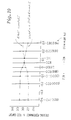
- Test tyres were made, varying the mean cord spacing D while keeping the cord diameter (d) at a constant value, and the tyres were tested for steering performances and ride comfort.
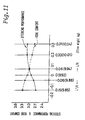
- the upper end 9a of the rubber spacer 9 is spaced apart from the axially outer belt edge 7e, but it can be overlapped with the outer belt edge 7e.
- test tyres were made, varying the above-mentioned space Z and overlap Z' by changing the position for the upper end 9a of the rubber spacer 9 while keeping the tyre section height H at a constant value, and the tyres were tested for a ride comfort and steering performances.
- the test results are shown in Fig.10. From a point of view of ride comfort, it is preferable that the upper end 9a of the rubber spacer 9 does not overlap with the outer belt edge 7e, providing a space therebetween, as shown in Fig.1.
- the space Z is 0.05 to 0.3 times, preferably 0.05 to 0.2 times the tyre section height H.
- the upper end 9a of the rubber spacer 9 overlaps with the outer belt edge 7e as shown in Fig.12(A).
- the overlap width Z' is 0.05 to 0.4 times, preferably 0.05 to 0.2 times the tyre section height H.
- the width is less than 0.05 times H, deformation is apt to concentrate between the rubber spacer 9 and the outer belt edge 7e, and the tyre is liable to be damaged.
- test tyres were further tested for durability, using a drum. (tyre load: 700 kg, tyre inner pressure: 2.0 kgf/cm 2 , rim size: 16X7JJ, drum diameter: 0.9 m, running speed: 80 km/h, running distance: 50000 km)
- the lower end 9b of the rubber spacer 9 is disposed radially inwards of the upper end of the bead apex 8, as shown in Fig.1, so as to form an overlap portion.
- test tyres were made changing the position of the lower end 9b of the rubber spacer 9 while keeping the tyre section height H at a constant value, and the tyres were tested for steering performances and ride comfort.
- the degree of improvement in the tyre lateral stiffness is substantially proportional to the width L.
- the width L exceeds 0.2 times the tyre section height H, steering performances are hardly improved, the ride comfort is deteriorated, and the tyre weight increases.
- width L is smaller than 0.05 times the tyre section height H, deformation is apt to concentrate in the overlap portion, and the tyre is liable to be damaged.
- the width L of the overlap portion is preferably set in the range of from 0.05 to 0.2 times the tyre section height H.
- the rubber composition of the spacer 9 has a complex elastic modulus E* which is the same as or larger than that of the carcass ply topping rubber 12. Furthermore, the rubber composition of the spacer 9 has a complex electic modulus E' which is lower than that of the bead apex rubber, and a hardness which is lower than that of the bead apex rubber.
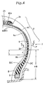
- Fig.4 shows a second embodiment of the present invention, in which the tyre 1 is provided with a carcass 6 consisting of a single carcass ply 6C.
- the carcass ply 6C comprises a main portion 20C extending between the bead cores 5 through the tread portion and sidewall portions 3, and a pair of turnup portions 21C turned up around the bead cores 5 from the inside to the outside of the tyre.
- the turnup portions 21C extend radially outwardly over the upper end of the bead apex 8 and the maximum tyre width position P.
- the edge 6Ce of each turnup is terminated between the outer edge 7e of the belt 7 and the carcass ply main portion 20C to be secured therebetween.
- this upper part and the carcass ply main portion 20C are adjacent each other.
- a rubber spacer 9 is disposed between the carcass ply main portion 20C and turnup portion 21C as shown in Figs.4 and 5 to form a spaced portion 10.
- the mean cord spacing D between the carcass cords in the carcass ply main portion 20C and the carcass cords 22 in the turnup portion 21C is set to be in the range of from 0.55 to 5.5 times the cord diameter (d).
- the upper end 9a of the rubber spacer 9 is spaced apart from the belt edge 7e, but the lower end 9b overlaps the bead apex 8.
- the width L of this overlap portion J is set in the range of from 0.05 to 0.20 times the tyre section height H.
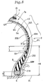
- Fig.8 shows still another embodiment of the present invention in which the tyre 1 is provided with a carcass 6 consisting of two carcass plies 6D and 6E.
- the carcass ply 6D consists of a carcass ply main portion 20D extending between the bead cores 5 through the tread portion and sidewall portions 3, and a pair of turnup portions 21D turned up around the bead cores 5 from the inside to outside of the tyre.
- the turnup portion 21D of the carcass ply 6D extends radially outwardly over the upper end of the bead apex 8 and maximum tyre width position P.
- the edge 6De of the turnup portion 21D is spaced apart from the outer edge 7e of the belt 7 in the example shown in the figure, but they can be overlapped each other.
- the carcass ply 6E consists of only a main portion 20E extending between the bead cores 5 through the tread portion and sidewall portions 3 and disposed axially outside of the carcass ply 6D.
- the carcass ply 6E is terminated at a distance S from the bead base line BL.
- the end thereof is located between the carcass ply main portion 20D of the carcass ply 6D and the bead apex 8, but the end can be located axially outward of the turnup portions 21D of the carcass ply 6D.
- the carcass ply main portions 20D and the carcass ply main portions 20E are adjacent each other, and a rubber spacer 9 is disposed therebetween to form a spaced portion 10, similarly to the above-mentioned first and second embodiment.
- the mean cord spacing D between the carcass cords in the carcass ply main portion 20D and the carcass cords in the carcass ply main portion 20E is in the range of from 0.55 to 5.5 times the cord diameter (d).
- the upper end 9a and lower end 9b of the rubber spacer 9 is constructed as explained above.
- the steering performances rigidity (response), response sharpness, response continuity, roll, and understeer, were evaluated into five ranks by the driver's feeling through an actual car test. The larger the value, the better the performance.
- the test tyres were mounted in a 3000cc passenger car. (Air pressure : 2.2 kg/sq.cm, Tyre load : 360 kg)
- the Ex.1 tyre having two carcass plies had a light weight and better performances in comparison with the Ref.2 tyre having a single carcass ply.
- the pneumatic radial tyres of the present invention is improved in steering performances while preventing the tyre weight from increasing.
- the present invention is suitably applied to a passenger car tyre.
- Tyre size 225/50R16 Ex.1 Ex.2 Ref.1 Ref.2 Ex.3 Ref.3 Ex.4
Landscapes
- Engineering & Computer Science (AREA)
- Mechanical Engineering (AREA)
- Tires In General (AREA)
Claims (8)
- Pneumatique à carcasse radiale pour automobile, comprenant une partie de bande de roulement (2), une paire de parties de flanc (3), une paire de parties (4) de talon ayant une tringle (5), une carcasse (6) disposée entre les parties de talon (4), une ceinture (7) disposée radialement à l'extérieur de la carcasse, une pointe (8) de bourrage de talon formée de caoutchouc, disposée dans chaque partie de talon (4) et disposée radialement vers l'extérieur de la tringle (5), dans lequel une partie de la carcasse placée entre chaque bord de ceinture et la position de largeur maximale du pneumatique a une entretoise (9) de caoutchouc, dans lequel la carcasse (6) comporte une nappe de câblés qui s'étend entre les parties de talon et qui est repliée autour des tringles (5) de l'intérieur vers l'extérieur du pneumatique pour former une paire de parties repliées et une partie principale entre celles-ci, caractérisé en ce que l'entretoise (9) de caoutchouc est placée entre des câblés de carcasse adjacents axialement (20A, 20B, 20C, 21C, 20D, 20E) faisant un angle de 70 à 90 ° avec l'équateur de pneumatique (C), la carcasse (6) est formée d'une nappe de câblés, cette nappe étant placée entre les parties de talon (4) et étant repliée autour des tringles (5) de l'intérieur vers l'extérieur du pneumatique pour la formation des deux parties repliées (21C) et de la partie intermédiaire principale (21A), et l'entretoise de caoutchouc (9) est placée entre la partie principale (20C) et chaque partie repliée (21C), et dans lequel l'extrémité radialement externe de l'entretoise de caoutchouc (9) est placée à distance du bord axialement externe de la ceinture (7), caractérisé en ce que l'espacement des câblés adjacents axialement est compris entre 0,55 et 5,5 fois le diamètre (d) des câblés (22), en ce que l'espace disposé entre l'extrémité radialement externe de l'entretoise de caoutchouc (9) et le bord axialement externe de la ceinture (7) est compris entre 0,05 et 0,3 fois la hauteur (H) en coupe du pneumatique, et en ce que l'extrémité radialement interne de l'entretoise (9) de caoutchouc est recouverte de l'extrémité radialement externe de la pointe de bourrage de talon (8), la largeur (J) de recouvrement est comprise entre 0,05 et 0,2 fois la hauteur (H) en coupe du pneumatique, et le matériau de l'entretoise (9) de caoutchouc a un module complexe d'élasticité E* qui est inférieur à celui du caoutchouc de la pointe de bourrage de talon et une dureté qui est inférieure à celle du caoutchouc de la pointe de bourrage de talon.
- Pneumatique à carcasse radiale pour automobile, comprenant une partie de bande de roulement (2), une paire de parties de flanc (3), une paire de parties (4) de talon ayant une tringle (5), une carcasse (6) disposée entre les parties de talon (4), une ceinture (7) disposée radialement à l'extérieur de la carcasse, une pointe (8) de bourrage de talon formée de caoutchouc, disposée dans chaque partie de talon (4) et disposée radialement vers l'extérieur de la tringle (5), dans lequel une partie de la carcasse placée entre chaque bord de ceinture et la position de largeur maximale du pneumatique a une entretoise (9) de caoutchouc, dans lequel la carcasse (6) comporte une nappe de câblés qui s'étend entre les parties de talon et qui est repliée autour des tringles (5) de l'intérieur vers l'extérieur du pneumatique pour former une paire de parties repliées et une partie principale entre celles-ci, dans lequel l'entretoise (9) de caoutchouc est placée entre des câblés de carcasse adjacents axialement (20A, 20B, 20C, 21C, 20D, 20E) faisant un angle de 70 à 90 ° avec l'équateur de pneumatique (C), dans lequel la carcasse (6) est formée d'une nappe de câblés, cette nappe étant placée entre les parties de talon (4) et étant repliée autour des tringles (5) de l'intérieur vers l'extérieur du pneumatique pour la formation des deux parties repliées (21C) et de la partie intermédiaire principale (21A), et l'entretoise de caoutchouc (9) est placée entre la partie principale (20C) et chaque partie repliée (21C), caractérisé en ce que l'espacement des câblés adjacents axialement est compris entre 0,55 et 5,5 fois le diamètre (d) des câblés (22), en ce que l'extrémité radialement externe de l'entretoise (9) de caoutchouc est recouverte du bord axialement externe de la ceinture, et la largeur de recouvrement est comprise entre 0,05 et 0,4 fois la hauteur (H) en coupe du pneumatique, et en ce que l'extrémité radialement interne de l'entretoise (9) de caoutchouc est recouverte de l'extrémité radialement externe de la pointe de bourrage de talon (8), la largeur (J) de recouvrement est comprise entre 0,05 et 0,2 fois la hauteur (H) en coupe du pneumatique, et le matériau de l'entretoise (9) de caoutchouc a un module complexe d'élasticité E* qui est inférieur à celui du caoutchouc de la pointe de bourrage de talon et une dureté qui est inférieure à celle du caoutchouc de la pointe de bourrage de talon.
- Pneumatique à carcasse radiale pour automobile, comprenant une partie de bande de roulement (2), une paire de parties de flanc (3), une paire de parties (4) de talon ayant une tringle (5), une carcasse (6) disposée entre les parties de talon (4), une ceinture (7) disposée radialement à l'extérieur de la carcasse, une pointe (8) de bourrage de talon formée de caoutchouc, disposée dans chaque partie de talon (4) et disposée radialement vers l'extérieur de la tringle (5), dans lequel une partie de la carcasse placée entre chaque bord de ceinture et la position de largeur maximale du pneumatique a une entretoise (9) de caoutchouc, dans lequel la carcasse (6) comporte une nappe de câblés qui s'étend entre les parties de talon et qui est repliée autour des tringles (5) de l'intérieur vers l'extérieur du pneumatique pour former une paire de parties repliées et une partie principale entre celles-ci, dans lequel l'entretoise (9) de caoutchouc est placée entre des câblés de carcasse adjacents axialement (20A, 20B, 20C, 21C, 20D, 20E) faisant un angle de 70 à 90 ° avec l'équateur de pneumatique (C), et dans lequel l'extrémité radialement externe de l'entretoise de caoutchouc (9) est placée à distance du bord axialement externe de la ceinture (7), si bien que l'espacement des câblés adjacents axialement est compris entre 0,55 et 5,5 fois le diamètre (d) des câblés (22), dans lequel la carcasse (6) comporte une nappe interne de câblés (6D) et une nappe externe de câblés (6E), la nappe interne (6D) étant placée entre les parties de talon (4) et étant repliée autour des tringles (5) de l'intérieur vers l'extérieur du pneumatique pour la formation des deux parties repliées (21D) et de la partie principale (20D) placée entre les parties repliées, la nappe externe (6E) étant disposée entre les parties de talon (4) et n'étant pas repliée autour des tringles (5) et délimitant une partie principale de cette nappe, et l'entretoise (9) de caoutchouc est placée entre les deux parties principales (20D, 20E) des deux nappes de carcasse, dans lequel l'espace disposé entre l'extrémité radialement externe de l'entretoise de caoutchouc (9) et le bord axialement externe de la ceinture (7) est compris entre 0,05 et 0,3 fois la hauteur (H) en coupe du pneumatique, et dans lequel l'extrémité radialement interne de l'entretoise (9) de caoutchouc est recouverte de l'extrémité radialement externe de la pointe de bourrage de talon (8), la largeur (J) de recouvrement est comprise entre 0,05 et 0,2 fois la hauteur (H) en coupe du pneumatique, et le matériau de l'entretoise (9) de caoutchouc a un module complexe d'élasticité E* qui est inférieur à celui du caoutchouc de la pointe de bourrage de talon et une dureté qui est inférieure à celle du caoutchouc de la pointe de bourrage de talon.
- Pneumatique à carcasse radiale pour automobile, comprenant une partie de bande de roulement (2), une paire de parties de flanc (3), une paire de parties (4) de talon ayant une tringle (5), une carcasse (6) disposée entre les parties de talon (4), une ceinture (7) disposée radialement à l'extérieur de la carcasse, une pointe (8) de bourrage de talon formée de caoutchouc, disposée dans chaque partie de talon (4) et disposée radialement vers l'extérieur de la tringle (5), dans lequel une partie de la carcasse placée entre chaque bord de ceinture et la position de largeur maximale du pneumatique a une entretoise (9) de caoutchouc, dans lequel la carcasse (6) comporte une nappe de câblés qui s'étend entre les parties de talon et qui est repliée autour des tringles (5) de l'intérieur vers l'extérieur du pneumatique pour former une paire de parties repliées et une partie principale entre celles-ci, dans lequel l'entretoise (9) de caoutchouc est placée entre des câblés de carcasse adjacents axialement (20A, 20B, 20C, 21C, 20D, 20E) faisant un angle de 70 à 90 ° avec l'équateur de pneumatique (C), caractérisé en ce que l'espacement des câblés adjacents axialement est compris entre 0,55 et 5,5 fois le diamètre (d) des câblés (22), en ce que la carcasse (6) comporte une nappe interne de câblés (6D) et une nappe externe de câblés (6E), la nappe interne (6D) étant placée entre les parties de talon (4) et étant repliée autour des tringles (5) de l'intérieur vers l'extérieur du pneumatique pour la formation des deux parties repliées (21D) et de la partie principale (20D) placée entre les parties repliées, la nappe externe (6E) étant disposée entre les parties de talon (4) et n'étant pas repliée autour des tringles (5) et délimitant une partie principale de cette nappe, et l'entretoise (9) de caoutchouc est placée entre les deux parties principales (20D, 20E) des deux nappes de carcasse, en ce que l'extrémité radialement externe de l'entretoise (9) de caoutchouc est recouverte du bord axialement externe de la ceinture, et la largeur de recouvrement est comprise entre 0,05 et 0,4 fois la hauteur (H) en coupe du pneumatique, et en ce que l'extrémité radialement interne de l'entretoise (9) de caoutchouc est recouverte de l'extrémité radialement externe de la pointe de bourrage de talon (8), la largeur (J) de recouvrement est comprise entre 0,05 et 0,2 fois la hauteur (H) en coupe du pneumatique, et le matériau de l'entretoise (9) de caoutchouc a un module complexe d'élasticité E* qui est inférieur à celui du caoutchouc de la pointe de bourrage de talon et une dureté qui est inférieure à celle du caoutchouc de la pointe de bourrage de talon.
- Pneumatique à carcasse radiale pour automobile, comprenant une partie de bande de roulement (2), une paire de parties de flanc (3), une paire de parties (4) de talon ayant une tringle (5), une carcasse (6) disposée entre les parties de talon (4), une ceinture (7) disposée radialement à l'extérieur de la carcasse, une pointe (8) de bourrage de talon formée de caoutchouc, disposée dans chaque partie de talon (4) et disposée radialement vers l'extérieur de la tringle (5), dans lequel une partie de la carcasse placée entre chaque bord de ceinture et la position de largeur maximale du pneumatique a une entretoise (9) de caoutchouc, dans lequel la carcasse (6) comporte une nappe de câblés qui s'étend entre les parties de talon et qui est repliée autour des tringles (5) de l'intérieur vers l'extérieur du pneumatique pour former une paire de parties repliées et une partie principale entre celles-ci, dans lequel l'entretoise (9) de caoutchouc est placée entre des câblés de carcasse adjacents axialement (20A, 20B, 20C, 21C, 20D, 20E) faisant un angle de 70 à 90 ° avec l'équateur de pneumatique (C), et dans lequel l'extrémité radialement externe de l'entretoise de caoutchouc (9) est placée à distance du bord axialement externe de la ceinture (7), caractérisé en ce que que l'espacement des câblés adjacents axialement est compris entre 0,55 et 5,5 fois le diamètre (d) des câblés (22), en ce que la carcasse (6) comporte deux nappes de câblés (6A, 6B), chaque nappe étant placée entre les parties de talon (4) et étant repliée autour des tringles (5) de l'intérieur vers l'extérieur du pneumatique pour la formation des paires de parties repliées (21A, 21B) et de parties principales (20A, 20B) entre les parties repliées, et l'entretoise (9) de caoutchouc est placée entre les deux parties principales (20A, 20B) des deux nappes de carcasse, en ce que l'espace disposé entre l'extrémité radialement externe de l'entretoise de caoutchouc (9) et le bord axialement externe de la ceinture (7) est compris entre 0,05 et 0,3 fois la hauteur (H) en coupe du pneumatique, et en ce que l'extrémité radialement interne de l'entretoise (9) de caoutchouc est recouverte de l'extrémité radialement externe de la pointe de bourrage de talon (8), la largeur (J) de recouvrement est comprise entre 0,05 et 0,2 fois la hauteur (H) en coupe du pneumatique, et le matériau de l'entretoise (9) de caoutchouc a un module complexe d'élasticité E* qui est inférieur à celui du caoutchouc de la pointe de bourrage de talon et une dureté qui est inférieure à celle du caoutchouc de la pointe de bourrage de talon.
- Pneumatique à carcasse radiale pour automobile, comprenant une partie de bande de roulement (2), une paire de parties de flanc (3), une paire de parties (4) de talon ayant une tringle (5), une carcasse (6) disposée entre les parties de talon (4), une ceinture (7) disposée radialement à l'extérieur de la carcasse, une pointe (8) de bourrage de talon formée de caoutchouc, disposée dans chaque partie de talon (4) et disposée radialement vers l'extérieur de la tringle (5), dans lequel une partie de la carcasse placée entre chaque bord de ceinture et la position de largeur maximale du pneumatique a une entretoise (9) de caoutchouc, dans lequel la carcasse (6) comporte une nappe de câblés qui s'étend entre les parties de talon et qui est repliée autour des tringles (5) de l'intérieur vers l'extérieur du pneumatique pour former une paire de parties repliées et une partie principale entre celles-ci, dans lequel l'entretoise (9) de caoutchouc est placée entre des câblés de carcasse adjacents axialement (20A, 20B, 20C, 21C, 20D, 20E) faisant un angle de 70 à 90 ° avec l'équateur de pneumatique (C), et dans lequel l'extrémité radialement externe de l'entretoise de caoutchouc (9) est placée à distance du bord axialement externe de la ceinture (7), caractérisé en ce que que l'espacement des câblés adjacents axialement est compris entre 0,55 et 5,5 fois le diamètre (d) des câblés (22), en ce que la carcasse (6) comporte deux nappes de câblés (6A, 6B), chaque nappe étant placée entre les parties de talon (4) et étant repliée autour des tringles (5) de l'intérieur vers l'extérieur du pneumatique pour la formation des paires de parties repliées (21A, 21B) et de parties principales (20A, 20B) entre les parties repliées, et l'entretoise (9) de caoutchouc est placée entre les deux parties principales (20A, 20B) des deux nappes de carcasse, en ce que l'extrémité radialement externe de l'entretoise (9) de caoutchouc est recouverte du bord axialement externe de la ceinture, et la largeur de recouvrement est comprise entre 0,05 et 0,4 fois la hauteur (H) en coupe du pneumatique, et en ce que l'extrémité radialement interne de l'entretoise (9) de caoutchouc est recouverte de l'extrémité radialement externe de la pointe de bourrage de talon (8), la largeur (J) de recouvrement est comprise entre 0,05 et 0,2 fois la hauteur (H) en coupe du pneumatique, et le matériau de l'entretoise (9) de caoutchouc a un module complexe d'élasticité E* qui est inférieur à celui du caoutchouc de la pointe de bourrage de talon et une dureté qui est inférieure à celle du caoutchouc de la pointe de bourrage de talon.
- Pneumatique à carcasse radiale selon la revendication 5 ou 6, caractérisé en ce que les extrémités radialement externes (6Ce) des parties repliées de l'une des deux nappes de carcasse sont fixées entre la ceinture (7) et la partie principale (6) de nappe de carcasse.
- Pneumatique à carcasse radiale selon la revendication 3 ou 4, caractérisé en ce que les extrémités radialement externes des parties repliées (6De) sont fixées entre la ceinture (7) et la partie principale de nappe de carcasse.
Applications Claiming Priority (6)
| Application Number | Priority Date | Filing Date | Title |
|---|---|---|---|
| JP219123/93 | 1993-08-10 | ||
| JP21912393 | 1993-08-10 | ||
| JP21912393 | 1993-08-10 | ||
| JP16883294 | 1994-06-27 | ||
| JP6168832A JP2916082B2 (ja) | 1993-08-10 | 1994-06-27 | 空気入りラジアルタイヤ |
| JP168832/94 | 1994-06-27 |
Publications (3)
| Publication Number | Publication Date |
|---|---|
| EP0638445A1 EP0638445A1 (fr) | 1995-02-15 |
| EP0638445B1 EP0638445B1 (fr) | 1997-10-22 |
| EP0638445B2 true EP0638445B2 (fr) | 2000-09-06 |
Family
ID=26492376
Family Applications (1)
| Application Number | Title | Priority Date | Filing Date |
|---|---|---|---|
| EP94305876A Expired - Lifetime EP0638445B2 (fr) | 1993-08-10 | 1994-08-08 | Pneumatique à carcasse radiale |
Country Status (4)
| Country | Link |
|---|---|
| US (3) | US5639321A (fr) |
| EP (1) | EP0638445B2 (fr) |
| JP (1) | JP2916082B2 (fr) |
| DE (1) | DE69406380T3 (fr) |
Families Citing this family (34)
| Publication number | Priority date | Publication date | Assignee | Title |
|---|---|---|---|---|
| US6293327B1 (en) * | 1997-06-20 | 2001-09-25 | Sumitomo Rubber Industries, Ltd. | Pneumatic tire |
| JP3332330B2 (ja) * | 1997-06-27 | 2002-10-07 | 住友ゴム工業株式会社 | 空気入りタイヤ及びその製造方法 |
| US6527025B1 (en) * | 1998-09-11 | 2003-03-04 | Sumitomo Rubber Industries, Ltd. | Tubeless tire |
| DE19859157A1 (de) * | 1998-12-21 | 2000-06-29 | Dunlop Gmbh | Fahrzeugluftreifen |
| JP4537517B2 (ja) * | 1999-10-29 | 2010-09-01 | 住友ゴム工業株式会社 | 空気入りラジアルタイヤの製造方法 |
| EP1101633B1 (fr) * | 1999-11-18 | 2006-02-01 | Société de Technologie Michelin | Pneumatique avec zone basse découplée |
| US6470938B1 (en) * | 2000-04-27 | 2002-10-29 | Bridgestone/Firestone North American Tire, Llc | Pneumatic tire having layer of rubber disposed between the body and belt package |
| GB2361680B (en) * | 2000-04-28 | 2002-08-28 | Goodyear Tire & Rubber | A radial ply tire having a sidewall reinforcement |
| JP4073606B2 (ja) * | 2000-05-17 | 2008-04-09 | 住友ゴム工業株式会社 | 空気入りタイヤ |
| US6450223B1 (en) * | 2000-05-23 | 2002-09-17 | The Goodyear Tire & Rubber Company | Pneumatic tire having improved wet traction |
| US6553306B2 (en) | 2001-02-21 | 2003-04-22 | Zf Meritor, Llc | System for controlling engine braking in a vehicle driveline |
| AU2007203377B2 (en) * | 2001-03-20 | 2010-05-13 | Kumho Tire Co., Inc | Pneumatic tire with reinforced bead part |
| KR100393476B1 (ko) * | 2001-03-20 | 2003-08-02 | 금호산업주식회사 | 비드부를 보강한 공기입 타이어 |
| US20040007305A1 (en) * | 2001-04-16 | 2004-01-15 | Kiyoshi Ueyoko | Pneumatic tire |
| KR100426005B1 (ko) * | 2001-09-15 | 2004-04-06 | 금호타이어 주식회사 | 변형에너지 분산형 레디얼 타이어 |
| US20060124221A1 (en) * | 2004-12-13 | 2006-06-15 | Richards Gary W | Method and apparatus for torque wind-up reduction in a free-rolling dual tire assembly |
| JP4567482B2 (ja) * | 2005-02-14 | 2010-10-20 | 住友ゴム工業株式会社 | 空気入りタイヤ |
| DE102005051683A1 (de) * | 2005-10-28 | 2007-05-03 | Continental Aktiengesellschaft | Fahrzeugluftreifen |
| JP4916783B2 (ja) * | 2006-06-20 | 2012-04-18 | 東洋ゴム工業株式会社 | 空気入りタイヤ |
| US20090294007A1 (en) * | 2008-06-02 | 2009-12-03 | Walter Vorreiter | Performance tire with sidewall insert |
| JP5358333B2 (ja) * | 2009-07-24 | 2013-12-04 | 株式会社ブリヂストン | 空気入りタイヤ |
| JP5487802B2 (ja) * | 2009-08-21 | 2014-05-14 | 横浜ゴム株式会社 | 空気入りタイヤ |
| US8517072B2 (en) * | 2010-02-04 | 2013-08-27 | Bridgestone Americas Tire Operations, Llc | Tire having gum strip and chafer |
| US8413700B2 (en) * | 2010-02-04 | 2013-04-09 | Bridgestone Americas Tire Operations, Llc | Tire having staggered turn-ups |
| EP2631092B1 (fr) * | 2010-10-19 | 2017-04-12 | Bridgestone Corporation | Pneumatique |
| JP6338291B2 (ja) * | 2012-10-26 | 2018-06-06 | イー・アイ・デュポン・ドウ・ヌムール・アンド・カンパニーE.I.Du Pont De Nemours And Company | タイヤまたはベルトなどの物体の補強のための複合層 |
| US9227467B2 (en) * | 2013-07-22 | 2016-01-05 | E I Du Pont De Nemours And Company | Pneumatic tire |
| JP6720537B2 (ja) * | 2016-01-08 | 2020-07-08 | 住友ゴム工業株式会社 | 空気入りタイヤ |
| JP6996243B2 (ja) * | 2017-11-14 | 2022-01-17 | 住友ゴム工業株式会社 | 重荷重用空気入りタイヤ |
| JP6996242B2 (ja) * | 2017-11-14 | 2022-01-17 | 住友ゴム工業株式会社 | 重荷重用空気入りタイヤ |
| JP6667045B1 (ja) * | 2019-11-27 | 2020-03-18 | 横浜ゴム株式会社 | 空気入りタイヤ |
| JP7484507B2 (ja) * | 2020-07-08 | 2024-05-16 | 住友ゴム工業株式会社 | 空気入りタイヤ |
| CN116917145A (zh) * | 2021-02-25 | 2023-10-20 | 住友橡胶工业株式会社 | 轮胎 |
| CN114872496B (zh) * | 2022-06-14 | 2024-01-05 | 青岛双星轮胎工业有限公司 | 一种适用于ev纯电动乘用车的轮胎子口结构 |
Citations (16)
| Publication number | Priority date | Publication date | Assignee | Title |
|---|---|---|---|---|
| US3052275A (en) † | 1959-05-12 | 1962-09-04 | Goodyear Tire & Rubber | Pneumatic tire |
| US3292681A (en) † | 1963-02-01 | 1966-12-20 | Michelin & Cie | Pneumatic tires |
| US3542108A (en) † | 1968-05-23 | 1970-11-24 | Goodyear Tire & Rubber | Tire |
| US3717190A (en) † | 1970-03-01 | 1973-02-20 | Michelin & Cie | Radial tire having interposed plies at tread reinforcement edges |
| US3916968A (en) † | 1973-01-29 | 1975-11-04 | Pneumatiques Caoutchouc Mfg | Vehicle tires |
| US4023608A (en) † | 1973-09-08 | 1977-05-17 | Continental Gummi-Werke Aktiengesellschaft | Pneumatic vehicle tire |
| US4086948A (en) † | 1975-07-30 | 1978-05-02 | Bridgestone Tire Company Limited | Radial tire for heavy load vehicles |
| JPS54136003A (en) † | 1978-04-07 | 1979-10-22 | Yokohama Rubber Co Ltd:The | Pneumatic tire |
| GB2104011A (en) † | 1981-06-19 | 1983-03-02 | Uniroyal Englebert Gmbh | Pneumatic vehicle tyre |
| JPS6082410A (ja) † | 1983-10-13 | 1985-05-10 | Sumitomo Rubber Ind Ltd | 乗用車用ラジアルタイヤ |
| JPS6171202A (ja) † | 1984-09-14 | 1986-04-12 | Sumitomo Rubber Ind Ltd | 乗用車用ラジアルタイヤ |
| JPS624613A (ja) † | 1985-06-28 | 1987-01-10 | Yokohama Rubber Co Ltd:The | 空気入りタイヤ |
| JPS6483411A (en) † | 1987-09-28 | 1989-03-29 | Yokohama Rubber Co Ltd | Radial tire |
| US5007472A (en) † | 1989-04-26 | 1991-04-16 | The Yokohama Rubber Co., Ltd. | Pneumatic radial tire with improved bead structure |
| JPH03204313A (ja) † | 1989-12-29 | 1991-09-05 | Sumitomo Rubber Ind Ltd | 偏平ラジアルタイヤ |
| EP0535938A1 (fr) † | 1991-09-30 | 1993-04-07 | Sumitomo Rubber Industries Limited | Bandage pneumatique radial |
Family Cites Families (7)
| Publication number | Priority date | Publication date | Assignee | Title |
|---|---|---|---|---|
| US3682217A (en) * | 1970-06-09 | 1972-08-08 | Alfred Marzocchi | Tire construction featuring glass and organic cord carcass plies |
| JPS55110605A (en) * | 1979-02-19 | 1980-08-26 | Bridgestone Corp | Pneumatic bicycle tire having good high-speed stability |
| JPS57159806U (fr) * | 1981-04-03 | 1982-10-07 | ||
| IT1163837B (it) * | 1983-07-22 | 1987-04-08 | Pirelli | Pneumatico per motocicli |
| US5361820A (en) * | 1991-09-30 | 1994-11-08 | Sumitomo Rubber Industries, Ltd. | Pneumatic radial tire |
| JPH06122302A (ja) * | 1992-10-12 | 1994-05-06 | Bridgestone Corp | 空気入りラジアルタイヤ |
| JPH06127211A (ja) * | 1992-10-13 | 1994-05-10 | Bridgestone Corp | 空気入りラジアルタイヤの組合せ体 |
-
1994
- 1994-06-27 JP JP6168832A patent/JP2916082B2/ja not_active Expired - Lifetime
- 1994-08-03 US US08/285,142 patent/US5639321A/en not_active Expired - Lifetime
- 1994-08-08 DE DE69406380T patent/DE69406380T3/de not_active Expired - Lifetime
- 1994-08-08 EP EP94305876A patent/EP0638445B2/fr not_active Expired - Lifetime
-
1997
- 1997-01-24 US US08/788,130 patent/US5820711A/en not_active Expired - Lifetime
- 1997-01-24 US US08/788,168 patent/US5879485A/en not_active Expired - Lifetime
Patent Citations (16)
| Publication number | Priority date | Publication date | Assignee | Title |
|---|---|---|---|---|
| US3052275A (en) † | 1959-05-12 | 1962-09-04 | Goodyear Tire & Rubber | Pneumatic tire |
| US3292681A (en) † | 1963-02-01 | 1966-12-20 | Michelin & Cie | Pneumatic tires |
| US3542108A (en) † | 1968-05-23 | 1970-11-24 | Goodyear Tire & Rubber | Tire |
| US3717190A (en) † | 1970-03-01 | 1973-02-20 | Michelin & Cie | Radial tire having interposed plies at tread reinforcement edges |
| US3916968A (en) † | 1973-01-29 | 1975-11-04 | Pneumatiques Caoutchouc Mfg | Vehicle tires |
| US4023608A (en) † | 1973-09-08 | 1977-05-17 | Continental Gummi-Werke Aktiengesellschaft | Pneumatic vehicle tire |
| US4086948A (en) † | 1975-07-30 | 1978-05-02 | Bridgestone Tire Company Limited | Radial tire for heavy load vehicles |
| JPS54136003A (en) † | 1978-04-07 | 1979-10-22 | Yokohama Rubber Co Ltd:The | Pneumatic tire |
| GB2104011A (en) † | 1981-06-19 | 1983-03-02 | Uniroyal Englebert Gmbh | Pneumatic vehicle tyre |
| JPS6082410A (ja) † | 1983-10-13 | 1985-05-10 | Sumitomo Rubber Ind Ltd | 乗用車用ラジアルタイヤ |
| JPS6171202A (ja) † | 1984-09-14 | 1986-04-12 | Sumitomo Rubber Ind Ltd | 乗用車用ラジアルタイヤ |
| JPS624613A (ja) † | 1985-06-28 | 1987-01-10 | Yokohama Rubber Co Ltd:The | 空気入りタイヤ |
| JPS6483411A (en) † | 1987-09-28 | 1989-03-29 | Yokohama Rubber Co Ltd | Radial tire |
| US5007472A (en) † | 1989-04-26 | 1991-04-16 | The Yokohama Rubber Co., Ltd. | Pneumatic radial tire with improved bead structure |
| JPH03204313A (ja) † | 1989-12-29 | 1991-09-05 | Sumitomo Rubber Ind Ltd | 偏平ラジアルタイヤ |
| EP0535938A1 (fr) † | 1991-09-30 | 1993-04-07 | Sumitomo Rubber Industries Limited | Bandage pneumatique radial |
Also Published As
| Publication number | Publication date |
|---|---|
| DE69406380T2 (de) | 1998-02-26 |
| EP0638445B1 (fr) | 1997-10-22 |
| JPH07101203A (ja) | 1995-04-18 |
| DE69406380T3 (de) | 2000-12-28 |
| US5639321A (en) | 1997-06-17 |
| US5820711A (en) | 1998-10-13 |
| EP0638445A1 (fr) | 1995-02-15 |
| US5879485A (en) | 1999-03-09 |
| DE69406380D1 (de) | 1997-11-27 |
| JP2916082B2 (ja) | 1999-07-05 |
Similar Documents
| Publication | Publication Date | Title |
|---|---|---|
| EP0638445B2 (fr) | Pneumatique à carcasse radiale | |
| EP1481822B1 (fr) | Bandage pneumatique radiale | |
| EP0844110B1 (fr) | Bandage pneumatique | |
| US5200006A (en) | Pneumatic tire with uniform ground pressure at the tread face | |
| JP2009001073A (ja) | 空気入りラジアルタイヤ | |
| EP0297889A2 (fr) | Bandage pneumatique | |
| EP1366930B1 (fr) | Bandages pneumatiques radiaux pour poids-lourds | |
| EP0882607B1 (fr) | Bandage pneumatique radial | |
| JP2002002216A (ja) | 空気入りタイヤ | |
| EP0732226B1 (fr) | Ceinture de renforcement pour bandage pneumatique | |
| US5129973A (en) | Motorcycle tire | |
| EP0667250B1 (fr) | Bandage pneumatique et son procédé de fabrication | |
| JP2000203215A (ja) | 空気入りタイヤ | |
| JPH05238208A (ja) | 空気入りタイヤ | |
| US5351735A (en) | Pneumatic tire with belt ply including both steel cords and aromatic polyamide cords | |
| EP0976584B1 (fr) | Bandage pneumatique pour moto | |
| EP1182060B1 (fr) | Bandage pneumatique | |
| US20020112798A1 (en) | Radial ply tire having a sidewall reinforcement | |
| JP3779893B2 (ja) | 空気入りラジアルタイヤ | |
| EP0835768B1 (fr) | Bandages pneumatiques | |
| EP1488939B1 (fr) | Pneumatique | |
| JPH0725213A (ja) | 空気入りタイヤ | |
| JPH07156607A (ja) | 空気入りラジアルタイヤ | |
| JP3254190B2 (ja) | 空気入りラジアルタイヤ | |
| JPH08175132A (ja) | 空気入りラジアルタイヤ |
Legal Events
| Date | Code | Title | Description |
|---|---|---|---|
| PUAI | Public reference made under article 153(3) epc to a published international application that has entered the european phase |
Free format text: ORIGINAL CODE: 0009012 |
|
| AK | Designated contracting states |
Kind code of ref document: A1 Designated state(s): DE FR GB IT |
|
| 17P | Request for examination filed |
Effective date: 19950328 |
|
| 17Q | First examination report despatched |
Effective date: 19960228 |
|
| GRAG | Despatch of communication of intention to grant |
Free format text: ORIGINAL CODE: EPIDOS AGRA |
|
| GRAH | Despatch of communication of intention to grant a patent |
Free format text: ORIGINAL CODE: EPIDOS IGRA |
|
| RAP1 | Party data changed (applicant data changed or rights of an application transferred) |
Owner name: SUMITOMO RUBBER INDUSTRIES LTD. |
|
| GRAH | Despatch of communication of intention to grant a patent |
Free format text: ORIGINAL CODE: EPIDOS IGRA |
|
| GRAA | (expected) grant |
Free format text: ORIGINAL CODE: 0009210 |
|
| AK | Designated contracting states |
Kind code of ref document: B1 Designated state(s): DE FR GB IT |
|
| ITF | It: translation for a ep patent filed | ||
| REF | Corresponds to: |
Ref document number: 69406380 Country of ref document: DE Date of ref document: 19971127 |
|
| ET | Fr: translation filed | ||
| PLBQ | Unpublished change to opponent data |
Free format text: ORIGINAL CODE: EPIDOS OPPO |
|
| PLBI | Opposition filed |
Free format text: ORIGINAL CODE: 0009260 |
|
| PLBF | Reply of patent proprietor to notice(s) of opposition |
Free format text: ORIGINAL CODE: EPIDOS OBSO |
|
| 26 | Opposition filed |
Opponent name: BRIDGESTONE CORPORATION Effective date: 19980720 |
|
| PLBF | Reply of patent proprietor to notice(s) of opposition |
Free format text: ORIGINAL CODE: EPIDOS OBSO |
|
| PLBF | Reply of patent proprietor to notice(s) of opposition |
Free format text: ORIGINAL CODE: EPIDOS OBSO |
|
| PLAW | Interlocutory decision in opposition |
Free format text: ORIGINAL CODE: EPIDOS IDOP |
|
| PLAW | Interlocutory decision in opposition |
Free format text: ORIGINAL CODE: EPIDOS IDOP |
|
| PUAH | Patent maintained in amended form |
Free format text: ORIGINAL CODE: 0009272 |
|
| STAA | Information on the status of an ep patent application or granted ep patent |
Free format text: STATUS: PATENT MAINTAINED AS AMENDED |
|
| 27A | Patent maintained in amended form |
Effective date: 20000906 |
|
| AK | Designated contracting states |
Kind code of ref document: B2 Designated state(s): DE FR GB IT |
|
| ITF | It: translation for a ep patent filed | ||
| ET3 | Fr: translation filed ** decision concerning opposition | ||
| REG | Reference to a national code |
Ref country code: GB Ref legal event code: IF02 |
|
| PGFP | Annual fee paid to national office [announced via postgrant information from national office to epo] |
Ref country code: GB Payment date: 20060802 Year of fee payment: 13 |
|
| PGFP | Annual fee paid to national office [announced via postgrant information from national office to epo] |
Ref country code: IT Payment date: 20060831 Year of fee payment: 13 |
|
| GBPC | Gb: european patent ceased through non-payment of renewal fee |
Effective date: 20070808 |
|
| PG25 | Lapsed in a contracting state [announced via postgrant information from national office to epo] |
Ref country code: GB Free format text: LAPSE BECAUSE OF NON-PAYMENT OF DUE FEES Effective date: 20070808 |
|
| PGFP | Annual fee paid to national office [announced via postgrant information from national office to epo] |
Ref country code: FR Payment date: 20080818 Year of fee payment: 15 |
|
| PG25 | Lapsed in a contracting state [announced via postgrant information from national office to epo] |
Ref country code: IT Free format text: LAPSE BECAUSE OF NON-PAYMENT OF DUE FEES Effective date: 20070808 |
|
| REG | Reference to a national code |
Ref country code: FR Ref legal event code: ST Effective date: 20100430 |
|
| PG25 | Lapsed in a contracting state [announced via postgrant information from national office to epo] |
Ref country code: FR Free format text: LAPSE BECAUSE OF NON-PAYMENT OF DUE FEES Effective date: 20090831 |
|
| PGFP | Annual fee paid to national office [announced via postgrant information from national office to epo] |
Ref country code: DE Payment date: 20130731 Year of fee payment: 20 |
|
| REG | Reference to a national code |
Ref country code: DE Ref legal event code: R071 Ref document number: 69406380 Country of ref document: DE |
|
| REG | Reference to a national code |
Ref country code: DE Ref legal event code: R071 Ref document number: 69406380 Country of ref document: DE |
|
| PG25 | Lapsed in a contracting state [announced via postgrant information from national office to epo] |
Ref country code: DE Free format text: LAPSE BECAUSE OF EXPIRATION OF PROTECTION Effective date: 20140809 |