EP0638430A2 - Papierschalen für einen durch Komputer gesteuerten Drucker - Google Patents
Papierschalen für einen durch Komputer gesteuerten Drucker Download PDFInfo
- Publication number
- EP0638430A2 EP0638430A2 EP94117234A EP94117234A EP0638430A2 EP 0638430 A2 EP0638430 A2 EP 0638430A2 EP 94117234 A EP94117234 A EP 94117234A EP 94117234 A EP94117234 A EP 94117234A EP 0638430 A2 EP0638430 A2 EP 0638430A2
- Authority
- EP
- European Patent Office
- Prior art keywords
- tray
- printer
- paper
- input tray
- input
- Prior art date
- Legal status (The legal status is an assumption and is not a legal conclusion. Google has not performed a legal analysis and makes no representation as to the accuracy of the status listed.)
- Granted
Links
Images


Classifications
-
- B—PERFORMING OPERATIONS; TRANSPORTING
- B41—PRINTING; LINING MACHINES; TYPEWRITERS; STAMPS
- B41J—TYPEWRITERS; SELECTIVE PRINTING MECHANISMS, i.e. MECHANISMS PRINTING OTHERWISE THAN FROM A FORME; CORRECTION OF TYPOGRAPHICAL ERRORS
- B41J11/00—Devices or arrangements of selective printing mechanisms, e.g. ink-jet printers or thermal printers, for supporting or handling copy material in sheet or web form
- B41J11/58—Supply holders for sheets or fan-folded webs, e.g. shelves, tables, scrolls, pile holders
-
- B—PERFORMING OPERATIONS; TRANSPORTING
- B41—PRINTING; LINING MACHINES; TYPEWRITERS; STAMPS
- B41J—TYPEWRITERS; SELECTIVE PRINTING MECHANISMS, i.e. MECHANISMS PRINTING OTHERWISE THAN FROM A FORME; CORRECTION OF TYPOGRAPHICAL ERRORS
- B41J13/00—Devices or arrangements of selective printing mechanisms, e.g. ink-jet printers or thermal printers, specially adapted for supporting or handling copy material in short lengths, e.g. sheets
- B41J13/10—Sheet holders, retainers, movable guides, or stationary guides
- B41J13/103—Sheet holders, retainers, movable guides, or stationary guides for the sheet feeding section
-
- B—PERFORMING OPERATIONS; TRANSPORTING
- B65—CONVEYING; PACKING; STORING; HANDLING THIN OR FILAMENTARY MATERIAL
- B65H—HANDLING THIN OR FILAMENTARY MATERIAL, e.g. SHEETS, WEBS, CABLES
- B65H1/00—Supports or magazines for piles from which articles are to be separated
- B65H1/04—Supports or magazines for piles from which articles are to be separated adapted to support articles substantially horizontally, e.g. for separation from top of pile
-
- B—PERFORMING OPERATIONS; TRANSPORTING
- B65—CONVEYING; PACKING; STORING; HANDLING THIN OR FILAMENTARY MATERIAL
- B65H—HANDLING THIN OR FILAMENTARY MATERIAL, e.g. SHEETS, WEBS, CABLES
- B65H31/00—Pile receivers
- B65H31/04—Pile receivers with movable end support arranged to recede as pile accumulates
- B65H31/08—Pile receivers with movable end support arranged to recede as pile accumulates the articles being piled one above another
- B65H31/10—Pile receivers with movable end support arranged to recede as pile accumulates the articles being piled one above another and applied at the top of the pile
-
- B—PERFORMING OPERATIONS; TRANSPORTING
- B65—CONVEYING; PACKING; STORING; HANDLING THIN OR FILAMENTARY MATERIAL
- B65H—HANDLING THIN OR FILAMENTARY MATERIAL, e.g. SHEETS, WEBS, CABLES
- B65H31/00—Pile receivers
- B65H31/22—Pile receivers removable or interchangeable
-
- B—PERFORMING OPERATIONS; TRANSPORTING
- B65—CONVEYING; PACKING; STORING; HANDLING THIN OR FILAMENTARY MATERIAL
- B65H—HANDLING THIN OR FILAMENTARY MATERIAL, e.g. SHEETS, WEBS, CABLES
- B65H2801/00—Application field
- B65H2801/03—Image reproduction devices
- B65H2801/21—Industrial-size printers, e.g. rotary printing press
Definitions
- the present invention relates to paper input and output trays for computer driven printers, and, more particularly, for inkjet printers.
- Inkjet printers have been provided with permanently attached paper input trays which necessarily give the printer a larger footprint during shipping thus requiring larger containers than are required for printers having detachable paper input trays.
- Printer paper input and output trays are regularly accessed by the printer operator and may be removable or permanently attached trays.
- the former are removed from the printer whenever the paper supply is exhausted for refilling with a stack of cut sheet paper.
- Printers with removable trays occupy a smaller footprint and therefore can be shipped in smaller containers but they have other drawbacks.
- Removable trays usually have a spring biased pusher plate beneath the paper stack for urging paper upwardly toward the printer feed rollers which remove one sheet at a time from the stack. Repeated removal, loading and reinstallation of the paper tray in the printer is a relatively easy task provided that care is taken to properly remove the tray, load the paper and reinstall the tray.
- removable paper trays, and the parts thereon such as the pusher plate and particularly the parts thereof that connect the tray to the printer, are subject to wear and eventual breakage.
- paper output trays are ordinarily easily removable trays which are hung on the front of the printer with plastic hooks or the like which are subject to breakage.
- printers such as inkjet printers which apply print to the paper using wet ink
- paper curl which usually takes place about the long center axis of the paper is also a problem.
- a semi-permanently attached paper tray system for a printer such as an inkjet printer is desired which, after installation by the user, is intended to remain in place on the printer even during paper loading so as to minimize the frequency of tray removal and attendant breakage.
- Both trays of the system should still be removable when desired without special tools and both trays should be easily accessible, preferably from the front of the printer, whereby paper can be loaded into the input tray without removal of either the paper input tray or the paper output tray.
- the paper input tray preferably should have no moving parts.
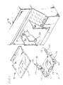
- FIG. 1 The exploded view of Figure 1 shows a printer 10, particularly a desk top printer such as an ink jet printer which has a paper input tray 20 and a paper output tray 70 located thereabove.
- the paper input tray 20 is first inserted into the printer and is retained therein and suspended from the printer chassis in cantilever fashion on the front of the printer.
- the paper output tray 70 is installed immediately above the paper input tray and is partially supported thereby.
- the trays are attached in such a fashion that they are, while removable, not intended to be regularly removed from the printer and in fact the input tray need not be removed from the printer for loading of a fresh supply of paper unlike various prior art paper cassettes or trays which must be removed whenever they are to be reloaded.
- the paper tray system of the present invention is referred to as a semi-permanently attached paper tray system.
- the paper input tray 20 will be described first.
- the input tray is molded plastic and has a horizontally extending shelf 22 and a pair of integrally molded upstanding sidewalls 24, 26.
- a paper size adjustment shelf 28 is slidably attached to the front side 30 of the paper input tray and has a front endwall 29 which is adjustably positionable to accommodate different sizes of paper in the tray as is well known.
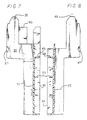
- Each of the sidewalls 24, 26 is in the form of an inverted channel having a rearwardly extending tray support arm 25, 27 which is received in the printer to support the paper input tray 20 in cantilever fashion from the front of the printer chassis.
- the left side inverted channel tray support arm 25 has an upper horizontally extending web 28 which comprises an output tray support surface.
- Vertically extending from the upper web 28 is an exterior flange 30 and an interior flange 32.
- the interior flange portion of the arm 25 extends rearwardly and has an outwardly extending hook 34 at it's free end.
- the hook has a beveled portion 36 to facilitate insertion of the arm into the printer left hand chassis plate 50 (Fig.
- the left arm interior flange 32 is laterally resilient so that the hook 34 will move laterally inwardly against the bias of the resilient arm 25 as the beveled surface 36 of the hook 34 engages the left printer chassis plate 50 during insertion of the paper input tray into the printer.
- the right hand arm 27 is also in the form of an inverted channel having a horizontally extending web 40 which comprises an output tray support surface and a pair of vertically extending interior and exterior flanges 42, 44.
- the interior flange 42 of the right arm also includes a hook 47 and the flange 42 of the right arm 27 is also preferably laterally resilient so that the right hand hook 46 can engage a complementary receiving pocket 62 in the right hand printer chassis plate 60 (Fig. 11)
- Each of the interior flanges 32, 42 on the left and right arms has a shaped male end 33, 43 to facilitate insertion of the arms into complementary shaped female receiving apertures 53, 63 in the printer chassis plates 50, 60.
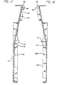
- Upwardly facing notches 37, 47 (Figs. 7 and 8) in the horizontally extending web support surfaces 28, 40 are provided to receive downwardly facing projections on the paper output tray 70 (to be described in more detail below) for properly positioning it above the paper input tray.
- the bottom of the paper shelf 22 is preferably molded with a plurality of criss-cross stiffening webs 23 and a pair of downwardly extending resilient rearwardly facing hooks 48, 49 (also seen in Figures 7 and 8) which engage printer chassis structure to resist upward movement of the front edge of the paper tray after it has been fully inserted into the printer.
- Figure 9 schematically shows a pivotally mounted spring biased paper shelf 130 having a pair of ears 132 at the front corners thereof which are received on opposed horizontally extending half axles 134 which extend from the left and right chassis plates 50, 60 of the printer (Figs. 1, 10 and 11).
- the lower end of compression spring 136 seats against the printer chassis and pushes the underside of the rear portion of the shelf 130 upwardly.
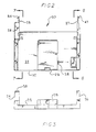
- Figures 10 and 11 respectively comprise perspective views of the left and right chassis plates 50, 60 of the printer which preferably comprise molded plastic vertically extending plates each having a front endwall 54, 64 and a generally horizontally extending interior female shelf 56, 66 which receives the male arms 25, 27 of the paper input tray 20.
- the beveled camming surfaces on the hooks 34, 36 on the interior ends of the arms are received in horizontally extending recesses 57, 67 in the side chassis plates until the hooks engage a beveled surfaces 58, 68 at the ends of the recesses 57, 67 which urges the resilient arms 25, 27 inwardly toward each other so that the hooks can enter retaining pockets 60, 62 in the chassis plates 50, 60.
- the paper output tray 70 comprises a molded plastic shelf 72 having a front horizontal portion 74 and a rear portion 76 which is downwardly inclined from the front portion at an angle of about 100.
- the downwardly inclined rear portion 76 includes a pair of upwardly extending sidewalls 78, 80 and a rear endwall 82 which is received in the printer.
- the rear inclined portion 76 of the shelf has a pair of downwardly extending flanges 84, 86 at the lateral edges thereof and a pair of guide ears 88, 90 at the lateral edges of the rear inclined portion.
- Each ear has a rearwardly open general horizontally extending elongated slot 92, 94 therein which engages a retaining pin which extends inwardly from each of the side chassis plates 50, 60 in the printer.
- the bottom plan view of Figure 16 shows that the ear 88 and one lateral edge 96 of the inclined portion (the right edge as seen in Figure 16) is inwardly offset from the marginal flange 86 of the front portion of the tray and has an inclined camming surface 98 which assists in centering the tray in the printer during installation thereof by engaging a correspondingly beveled surface on the left hand printer chassis sideplate 50.
- the output tray 70 also has a rearwardly and forwardly extending guide wing 100 depending downwardly from the undersurface of the rear portion 76 proximate the left side edge thereof.
- the wing 100 has a rearwardly and upwardly extending guide surface 102 and a forwardly and upwardly extending guide surface 104 which respectively engage the left hand printer chassis plate 50 to lift the left hand tray edge during attachment to and removal of the tray 70 from the printer.
- the paper output tray wing 100 is received in a pocket in the left hand printer chassis plate such that the front portion of the tray is properly oriented horizontally.
- Figures 17 and 18 show vertically extending webs 106, 108 integrally molded on the underside of the output tray whose lower edges 107, 109 define horizontally extending output tray support surfaces which engage the horizontally extending web support surfaces 28, 40 on the printer input tray arms 25, 27. Downwardly facing projections 110, 112 on the output tray support surfaces are received in the previously described upwardly facing notches 37, 47 on the paper input tray web support surfaces.
- a plurality of vertically extending stiffening webs 114 is also shown on the underside of the horizontal and inclined surfaces of the paper output tray which also has a sliding shelf 120 to accommodate paper of different lengths.
- the tray system thus far described, but not the spring biased paper shelf 130, is disassembled from the printer during shipment and, upon installation in the printer, the paper input tray 20 is first inserted with the hooks 34, 46 snapping into place in their respective pockets 60, 62 in the printer chassis and with the lower hooks 48, 49 engaging printer structure to resist upward movement of the front edge of the paper input tray.
- the laterally resilient arms 25, 27 of the paper input tray firmly resist removal of the tray from the printer under ordinary conditions but are sufficiently resilient to allow them to be manually bent toward each other for tray removal when desired.
- the paper output tray 70 is next inserted into the printer such that the ears 88, 90 and slots 92, 94 engage the pins in the printer at which time the downwardly extending projections 110, 112 are aligned with the notches 37, 47 in the paper input tray so that the paper output tray is supported in the printer and on the paper output tray.
- Inclination of the rear portion 76 of the paper output tray at an angle of about 10 with respect to the horizontal portion 74 of the output tray reduces paper curl along the longitudinal axis of the paper which typically occurs in wet process printers such as ink jet printers. This paper curl about the long axis is automatically straightened in the present output tray because the printed paper bends about the line of intersection between the horizontal portion of the tray and the inclined portion of the tray as it is deposited thereon.
- the present tray system occupies a small footprint in the shipping container and is also user friendly since the user need not remove the tray from the printer when loading paper therein nor manually straighten curl in the printed paper.
Landscapes
- Engineering & Computer Science (AREA)
- Mechanical Engineering (AREA)
- Pile Receivers (AREA)
- Sheets, Magazines, And Separation Thereof (AREA)
- Handling Of Cut Paper (AREA)
- Separation, Sorting, Adjustment, Or Bending Of Sheets To Be Conveyed (AREA)
Applications Claiming Priority (3)
| Application Number | Priority Date | Filing Date | Title |
|---|---|---|---|
| US08/055,650 US5354044A (en) | 1993-04-30 | 1993-04-30 | Paper trays for computer driven printer |
| US55650 | 1993-04-30 | ||
| EP94302959A EP0624478B1 (de) | 1993-04-30 | 1994-04-25 | Papierschalen für einen rechnergesteuerten Drucker |
Related Parent Applications (2)
| Application Number | Title | Priority Date | Filing Date |
|---|---|---|---|
| EP94302959.5 Division | 1994-04-25 | ||
| EP94302959A Division EP0624478B1 (de) | 1993-04-30 | 1994-04-25 | Papierschalen für einen rechnergesteuerten Drucker |
Publications (3)
| Publication Number | Publication Date |
|---|---|
| EP0638430A2 true EP0638430A2 (de) | 1995-02-15 |
| EP0638430A3 EP0638430A3 (de) | 1995-03-08 |
| EP0638430B1 EP0638430B1 (de) | 1997-07-23 |
Family
ID=21999270
Family Applications (2)
| Application Number | Title | Priority Date | Filing Date |
|---|---|---|---|
| EP94117234A Expired - Lifetime EP0638430B1 (de) | 1993-04-30 | 1994-04-25 | Papierschalen für einen durch Komputer gesteuerten Drucker |
| EP94302959A Expired - Lifetime EP0624478B1 (de) | 1993-04-30 | 1994-04-25 | Papierschalen für einen rechnergesteuerten Drucker |
Family Applications After (1)
| Application Number | Title | Priority Date | Filing Date |
|---|---|---|---|
| EP94302959A Expired - Lifetime EP0624478B1 (de) | 1993-04-30 | 1994-04-25 | Papierschalen für einen rechnergesteuerten Drucker |
Country Status (5)
| Country | Link |
|---|---|
| US (2) | US5354044A (de) |
| EP (2) | EP0638430B1 (de) |
| JP (1) | JP3404429B2 (de) |
| DE (2) | DE69404399T2 (de) |
| HK (1) | HK1000043A1 (de) |
Families Citing this family (33)
| Publication number | Priority date | Publication date | Assignee | Title |
|---|---|---|---|---|
| USD364185S (en) | 1994-06-06 | 1995-11-14 | Hewlett-Packard Company | Length adjuster for paper or other media for a printer |
| DE69525918T2 (de) * | 1994-12-28 | 2002-08-01 | Canon K.K., Tokio/Tokyo | Bildverarbeitungsgerät |
| USD373380S (en) | 1995-03-02 | 1996-09-03 | Hewlett-Packard Company | Inkjet printer |
| USD373378S (en) | 1995-03-02 | 1996-09-03 | Hewlett-Packard Company | Color inkjet printer |
| USD376615S (en) | 1995-03-03 | 1996-12-17 | Hewlett-Packard Company | Printer |
| USD379828S (en) * | 1995-03-03 | 1997-06-10 | Hewlett-Packard Company | Ink jet printer with bottom media input tray unit |
| USD378926S (en) * | 1995-03-03 | 1997-04-22 | Hewlett-Packard Company | Printer with media tray |
| USD378757S (en) * | 1995-03-03 | 1997-04-08 | Hewlett-Packard Company | Ink jet printer with multiple media input trays |
| USD382894S (en) * | 1996-02-29 | 1997-08-26 | Hewlett-Packard Company | Inkjet printer with covered media trays |
| US5711517A (en) * | 1996-03-07 | 1998-01-27 | Hewlett-Packard Company | Sheet media handling system |
| US5901952A (en) * | 1996-09-12 | 1999-05-11 | Hewlett-Packard Company | Paper size adjusting apparatus for a paper supply tray |
| CN1091691C (zh) * | 1996-09-18 | 2002-10-02 | 松下电器产业株式会社 | 图像印制装置 |
| US5853171A (en) * | 1997-01-16 | 1998-12-29 | Halpenny; Thomas J | Media level indicator |
| US6364553B1 (en) * | 2000-04-28 | 2002-04-02 | Hewlett-Packard Company | Greeting card feeder module for inkjet printing |
| US7515292B2 (en) * | 2000-11-25 | 2009-04-07 | Silverbrook Research Pty Ltd | Apparatus for cooling and storing produce |
| US6497479B1 (en) | 2001-04-27 | 2002-12-24 | Hewlett-Packard Company | Higher organic inks with good reliability and drytime |
| FR2850643A1 (fr) * | 2003-01-30 | 2004-08-06 | Neopost Ind | Dispositif de reception d'enveloppes |
| US20040201662A1 (en) * | 2003-04-09 | 2004-10-14 | Peter Hwang | Staggered input / output trays for hardcopy device |
| DE10323051A1 (de) * | 2003-05-20 | 2004-12-09 | Basys GmbH, Druck-, Lichtpaus- und Reprosysteme | Sammelablagevorrichtung |
| JP4411531B2 (ja) * | 2003-09-24 | 2010-02-10 | キヤノンファインテック株式会社 | 画像形成装置の給紙カセット |
| JP2005096347A (ja) * | 2003-09-26 | 2005-04-14 | Fuji Xerox Co Ltd | 拡張ボックス及び画像形成装置 |
| USD526347S1 (en) * | 2003-10-24 | 2006-08-08 | Brother Industries, Ltd. | Printer for cloth |
| SE527103C2 (sv) * | 2004-05-17 | 2005-12-20 | Plockmatic Int Ab | Häft- och falsmaskin |
| KR100739696B1 (ko) * | 2005-03-04 | 2007-07-13 | 삼성전자주식회사 | 용지적재유닛 및 이를 적용한 화상형성장치 |
| JP4818133B2 (ja) * | 2007-01-17 | 2011-11-16 | ニスカ株式会社 | 印刷装置 |
| US7828289B2 (en) * | 2007-06-08 | 2010-11-09 | Mumford Willard G | Stacker tray assembly for a photocopier |
| US8202015B2 (en) * | 2007-06-27 | 2012-06-19 | Hewlett-Packard Development Company, L.P. | Media tray assembly and a printer having the same |
| US20090127766A1 (en) * | 2007-11-15 | 2009-05-21 | Oki Data Corporation | Medium transportation apparatus, image reading apparatus, and multifunction product |
| JP4932936B2 (ja) * | 2009-11-17 | 2012-05-16 | キヤノンファインテック株式会社 | 画像形成装置 |
| JP6604309B2 (ja) * | 2016-10-28 | 2019-11-13 | 京セラドキュメントソリューションズ株式会社 | シート積載装置、及びシート積載装置を備える画像形成装置 |
| US11072509B2 (en) | 2017-07-31 | 2021-07-27 | Hewlett-Packard Development Company, L.P. | Media stops |
| WO2019089029A1 (en) * | 2017-11-02 | 2019-05-09 | Hewlett-Packard Development Company, L.P. | Media retention |
| USD1080452S1 (en) * | 2019-12-31 | 2025-06-24 | Lg Electronics Inc. | Shelf for indoor plant cultivators |
Family Cites Families (18)
| Publication number | Priority date | Publication date | Assignee | Title |
|---|---|---|---|---|
| US3510124A (en) * | 1968-03-18 | 1970-05-05 | Electrocopy Corp | Copy machine feed table |
| US3762813A (en) * | 1972-02-16 | 1973-10-02 | Dick Co Ab | Document feeder for electrostatic copier |
| JPS6228621Y2 (de) * | 1979-09-29 | 1987-07-22 | ||
| US4279504A (en) * | 1979-12-26 | 1981-07-21 | International Business Machines Corporation | Copier and multifunction paper cassette |
| US4582314A (en) * | 1982-11-19 | 1986-04-15 | Brother Kogyo Kabushiki Kaisha | Paper feeding apparatus |
| AT379109B (de) * | 1983-09-07 | 1985-11-25 | Siemens Ag Oesterreich | Papiervorratskassette fuer schreib- oder druckmaschinen |
| JPS60112468A (ja) * | 1983-11-25 | 1985-06-18 | Silver Seiko Ltd | 印字機の自動給紙装置 |
| JPS61279871A (ja) * | 1985-06-06 | 1986-12-10 | Canon Inc | 画像形成装置 |
| DE8606703U1 (de) * | 1986-03-11 | 1986-04-30 | Computer Gesellschaft Konstanz Mbh, 7750 Konstanz | Belegverarbeitungseinrichtung für Belege unterschiedlichen Formats |
| US4728963A (en) * | 1987-03-11 | 1988-03-01 | Hewlett-Packard Company | Single sheet ink-jet printer with passive drying system |
| JPH0668850B2 (ja) * | 1987-07-02 | 1994-08-31 | 日本電気株式会社 | 光ピックアップ装置 |
| JP2771278B2 (ja) * | 1989-09-20 | 1998-07-02 | 株式会社日立製作所 | ファクシミリ装置 |
| US5152622A (en) * | 1989-12-14 | 1992-10-06 | Hewlett-Packard Company | Printer with improved anti-skew mechanisms |
| JP2652082B2 (ja) * | 1990-11-13 | 1997-09-10 | キヤノン株式会社 | 原稿給送装置 |
| JPH04223964A (ja) * | 1990-12-26 | 1992-08-13 | Canon Inc | 画像形成装置のトレイ |
| JPH04100133U (de) * | 1991-02-08 | 1992-08-28 | ||
| JPH04365741A (ja) * | 1991-06-12 | 1992-12-17 | Fuji Xerox Co Ltd | 記録装置 |
| JPH05104819A (ja) * | 1991-10-18 | 1993-04-27 | Brother Ind Ltd | プリンタ |
-
1993
- 1993-04-30 US US08/055,650 patent/US5354044A/en not_active Expired - Lifetime
-
1994
- 1994-04-13 JP JP09933094A patent/JP3404429B2/ja not_active Expired - Fee Related
- 1994-04-25 EP EP94117234A patent/EP0638430B1/de not_active Expired - Lifetime
- 1994-04-25 DE DE69404399T patent/DE69404399T2/de not_active Expired - Fee Related
- 1994-04-25 EP EP94302959A patent/EP0624478B1/de not_active Expired - Lifetime
- 1994-04-25 DE DE69403731T patent/DE69403731T2/de not_active Expired - Fee Related
- 1994-10-11 US US08/321,336 patent/US5454553A/en not_active Expired - Lifetime
-
1997
- 1997-07-18 HK HK97101582A patent/HK1000043A1/en not_active IP Right Cessation
Also Published As
| Publication number | Publication date |
|---|---|
| EP0638430B1 (de) | 1997-07-23 |
| DE69403731T2 (de) | 1997-09-18 |
| JP3404429B2 (ja) | 2003-05-06 |
| DE69404399D1 (de) | 1997-08-28 |
| EP0638430A3 (de) | 1995-03-08 |
| HK1000043A1 (en) | 1997-10-24 |
| JPH0710296A (ja) | 1995-01-13 |
| EP0624478A2 (de) | 1994-11-17 |
| EP0624478B1 (de) | 1997-06-11 |
| EP0624478A3 (de) | 1995-03-08 |
| US5454553A (en) | 1995-10-03 |
| US5354044A (en) | 1994-10-11 |
| DE69404399T2 (de) | 1997-11-13 |
| DE69403731D1 (de) | 1997-07-17 |
Similar Documents
| Publication | Publication Date | Title |
|---|---|---|
| EP0638430B1 (de) | Papierschalen für einen durch Komputer gesteuerten Drucker | |
| HK1000043B (en) | Paper trays for computer driven printer | |
| US5120040A (en) | Sheet media tray and mechanism for feeding media of two different sizes | |
| US5620269A (en) | Print media transport apparatus for moving print media through a printer from a high volume input tray accessory | |
| US4854757A (en) | Automatic sheet feeder movable between active and inactive positions | |
| JP3452574B2 (ja) | 個々の枚葉紙積み紙を形成するための装置 | |
| EP0104948B1 (de) | Papierzufuhrvorrichtung für elektrostatisches Kopiergerät | |
| JP7547471B2 (ja) | プリンタのための印刷面位置付け機構 | |
| US5820281A (en) | Printer with discrete sheet load enhancement apparatus and method | |
| EP1559670B1 (de) | Medienkassette für ein automatisches Medienausgabegerät | |
| US5709381A (en) | Printer media tray with automatic skewing of stack of media | |
| US6951428B2 (en) | Print media loader | |
| US4717273A (en) | Multiple paper holder and method for a computer printer | |
| US20060163268A1 (en) | Napkin dispenser with dispensing control frame | |
| US5901952A (en) | Paper size adjusting apparatus for a paper supply tray | |
| US7543812B2 (en) | Media registration devices | |
| US6505827B2 (en) | Urging device provided with multiple loading member and paper feeding device incorporating the same | |
| US20050078997A1 (en) | Print cartridge support system | |
| CN215944065U (zh) | 一种具有卡纸适配座的打印机 | |
| WO1994015793A1 (en) | Print tray adaptor | |
| JPH0734056Y2 (ja) | 枚葉印刷機の排紙紙揃え装置 | |
| JPH09286556A (ja) | 用紙収容装置 | |
| JP3740292B2 (ja) | 記録装置 | |
| JPH0553710B2 (de) | ||
| JP3338984B2 (ja) | 紙案内板の支持構造 |
Legal Events
| Date | Code | Title | Description |
|---|---|---|---|
| PUAI | Public reference made under article 153(3) epc to a published international application that has entered the european phase |
Free format text: ORIGINAL CODE: 0009012 |
|
| PUAL | Search report despatched |
Free format text: ORIGINAL CODE: 0009013 |
|
| 17P | Request for examination filed |
Effective date: 19941115 |
|
| AC | Divisional application: reference to earlier application |
Ref document number: 624478 Country of ref document: EP |
|
| AK | Designated contracting states |
Kind code of ref document: A2 Designated state(s): DE FR GB IT |
|
| AK | Designated contracting states |
Kind code of ref document: A3 Designated state(s): DE FR GB IT |
|
| 17Q | First examination report despatched |
Effective date: 19960617 |
|
| GRAG | Despatch of communication of intention to grant |
Free format text: ORIGINAL CODE: EPIDOS AGRA |
|
| GRAH | Despatch of communication of intention to grant a patent |
Free format text: ORIGINAL CODE: EPIDOS IGRA |
|
| GRAH | Despatch of communication of intention to grant a patent |
Free format text: ORIGINAL CODE: EPIDOS IGRA |
|
| GRAA | (expected) grant |
Free format text: ORIGINAL CODE: 0009210 |
|
| AC | Divisional application: reference to earlier application |
Ref document number: 624478 Country of ref document: EP |
|
| AK | Designated contracting states |
Kind code of ref document: B1 Designated state(s): DE FR GB IT |
|
| REF | Corresponds to: |
Ref document number: 69404399 Country of ref document: DE Date of ref document: 19970828 |
|
| ET | Fr: translation filed | ||
| ITF | It: translation for a ep patent filed | ||
| PLBE | No opposition filed within time limit |
Free format text: ORIGINAL CODE: 0009261 |
|
| STAA | Information on the status of an ep patent application or granted ep patent |
Free format text: STATUS: NO OPPOSITION FILED WITHIN TIME LIMIT |
|
| 26N | No opposition filed | ||
| REG | Reference to a national code |
Ref country code: GB Ref legal event code: 732E |
|
| REG | Reference to a national code |
Ref country code: FR Ref legal event code: TP |
|
| REG | Reference to a national code |
Ref country code: GB Ref legal event code: IF02 |
|
| PGFP | Annual fee paid to national office [announced via postgrant information from national office to epo] |
Ref country code: DE Payment date: 20070531 Year of fee payment: 14 |
|
| PGFP | Annual fee paid to national office [announced via postgrant information from national office to epo] |
Ref country code: IT Payment date: 20070523 Year of fee payment: 14 |
|
| PGFP | Annual fee paid to national office [announced via postgrant information from national office to epo] |
Ref country code: FR Payment date: 20070417 Year of fee payment: 14 |
|
| PG25 | Lapsed in a contracting state [announced via postgrant information from national office to epo] |
Ref country code: DE Free format text: LAPSE BECAUSE OF NON-PAYMENT OF DUE FEES Effective date: 20081101 |
|
| REG | Reference to a national code |
Ref country code: FR Ref legal event code: ST Effective date: 20081231 |
|
| PG25 | Lapsed in a contracting state [announced via postgrant information from national office to epo] |
Ref country code: FR Free format text: LAPSE BECAUSE OF NON-PAYMENT OF DUE FEES Effective date: 20080430 |
|
| PG25 | Lapsed in a contracting state [announced via postgrant information from national office to epo] |
Ref country code: IT Free format text: LAPSE BECAUSE OF NON-PAYMENT OF DUE FEES Effective date: 20080425 |
|
| REG | Reference to a national code |
Ref country code: GB Ref legal event code: 732E Free format text: REGISTERED BETWEEN 20120329 AND 20120404 |
|
| PGFP | Annual fee paid to national office [announced via postgrant information from national office to epo] |
Ref country code: GB Payment date: 20130326 Year of fee payment: 20 |
|
| REG | Reference to a national code |
Ref country code: GB Ref legal event code: PE20 Expiry date: 20140424 |
|
| PG25 | Lapsed in a contracting state [announced via postgrant information from national office to epo] |
Ref country code: GB Free format text: LAPSE BECAUSE OF EXPIRATION OF PROTECTION Effective date: 20140424 |