EP0637509A1 - Tube pour transport d'essence - Google Patents
Tube pour transport d'essence Download PDFInfo
- Publication number
- EP0637509A1 EP0637509A1 EP94305715A EP94305715A EP0637509A1 EP 0637509 A1 EP0637509 A1 EP 0637509A1 EP 94305715 A EP94305715 A EP 94305715A EP 94305715 A EP94305715 A EP 94305715A EP 0637509 A1 EP0637509 A1 EP 0637509A1
- Authority
- EP
- European Patent Office
- Prior art keywords
- tube
- layer
- resin
- thickness
- adhesive layer
- Prior art date
- Legal status (The legal status is an assumption and is not a legal conclusion. Google has not performed a legal analysis and makes no representation as to the accuracy of the status listed.)
- Granted
Links
- 239000000446 fuel Substances 0.000 title claims abstract description 88
- 239000010410 layer Substances 0.000 claims abstract description 240
- 229920005989 resin Polymers 0.000 claims abstract description 122
- 239000011347 resin Substances 0.000 claims abstract description 122
- 239000012790 adhesive layer Substances 0.000 claims abstract description 82
- -1 Polybutylene naphthalate Polymers 0.000 claims abstract description 75
- YCKRFDGAMUMZLT-UHFFFAOYSA-N Fluorine atom Chemical compound [F] YCKRFDGAMUMZLT-UHFFFAOYSA-N 0.000 claims abstract description 37
- 239000011737 fluorine Substances 0.000 claims abstract description 37
- 229910052731 fluorine Inorganic materials 0.000 claims abstract description 37
- 239000004952 Polyamide Substances 0.000 claims abstract description 34
- 229920002647 polyamide Polymers 0.000 claims abstract description 34
- 125000005487 naphthalate group Chemical group 0.000 claims abstract description 22
- 229920001281 polyalkylene Polymers 0.000 claims abstract description 21
- 229920005992 thermoplastic resin Polymers 0.000 claims abstract description 7
- 229920002725 thermoplastic elastomer Polymers 0.000 claims abstract description 5
- 229920000728 polyester Polymers 0.000 claims description 51
- 229920001971 elastomer Polymers 0.000 claims description 44
- 239000000806 elastomer Substances 0.000 claims description 37
- 239000004433 Thermoplastic polyurethane Substances 0.000 claims description 22
- 229920002803 thermoplastic polyurethane Polymers 0.000 claims description 22
- 239000004840 adhesive resin Substances 0.000 claims description 21
- 229920006223 adhesive resin Polymers 0.000 claims description 21
- 150000001875 compounds Chemical class 0.000 claims description 21
- 239000000463 material Substances 0.000 claims description 19
- 229920000098 polyolefin Polymers 0.000 claims description 16
- CERQOIWHTDAKMF-UHFFFAOYSA-N Methacrylic acid Chemical compound CC(=C)C(O)=O CERQOIWHTDAKMF-UHFFFAOYSA-N 0.000 claims description 8
- 229920002614 Polyether block amide Polymers 0.000 claims description 7
- 239000005060 rubber Substances 0.000 claims description 7
- 125000003504 2-oxazolinyl group Chemical group O1C(=NCC1)* 0.000 claims description 5
- 239000004593 Epoxy Substances 0.000 claims description 5
- 150000008065 acid anhydrides Chemical class 0.000 claims description 5
- 125000003277 amino group Chemical group 0.000 claims description 5
- 125000002843 carboxylic acid group Chemical group 0.000 claims description 5
- GYZLOYUZLJXAJU-UHFFFAOYSA-N diglycidyl ether Chemical group C1OC1COCC1CO1 GYZLOYUZLJXAJU-UHFFFAOYSA-N 0.000 claims description 5
- 125000003055 glycidyl group Chemical group C(C1CO1)* 0.000 claims description 5
- IQPQWNKOIGAROB-UHFFFAOYSA-N isocyanate group Chemical group [N-]=C=O IQPQWNKOIGAROB-UHFFFAOYSA-N 0.000 claims description 5
- 125000002887 hydroxy group Chemical group [H]O* 0.000 claims description 4
- 229920006346 thermoplastic polyester elastomer Polymers 0.000 claims description 4
- 230000009471 action Effects 0.000 abstract description 26
- 230000004888 barrier function Effects 0.000 abstract description 26
- 230000000052 comparative effect Effects 0.000 description 43
- 239000000203 mixture Substances 0.000 description 34
- 229920000571 Nylon 11 Polymers 0.000 description 32
- 229920001707 polybutylene terephthalate Polymers 0.000 description 22
- LYCAIKOWRPUZTN-UHFFFAOYSA-N Ethylene glycol Chemical compound OCCO LYCAIKOWRPUZTN-UHFFFAOYSA-N 0.000 description 14
- 229920001577 copolymer Polymers 0.000 description 14
- JHWNWJKBPDFINM-UHFFFAOYSA-N Laurolactam Chemical compound O=C1CCCCCCCCCCCN1 JHWNWJKBPDFINM-UHFFFAOYSA-N 0.000 description 13
- 229920000299 Nylon 12 Polymers 0.000 description 13
- 230000005540 biological transmission Effects 0.000 description 13
- OKKJLVBELUTLKV-UHFFFAOYSA-N Methanol Chemical compound OC OKKJLVBELUTLKV-UHFFFAOYSA-N 0.000 description 12
- 229920000840 ethylene tetrafluoroethylene copolymer Polymers 0.000 description 11
- 229920002981 polyvinylidene fluoride Polymers 0.000 description 11
- 239000002033 PVDF binder Substances 0.000 description 10
- 230000007423 decrease Effects 0.000 description 10
- 239000007788 liquid Substances 0.000 description 9
- 238000002156 mixing Methods 0.000 description 9
- DNIAPMSPPWPWGF-UHFFFAOYSA-N Propylene glycol Chemical compound CC(O)CO DNIAPMSPPWPWGF-UHFFFAOYSA-N 0.000 description 8
- 238000000034 method Methods 0.000 description 8
- 238000000465 moulding Methods 0.000 description 8
- 239000002356 single layer Substances 0.000 description 8
- 239000004677 Nylon Substances 0.000 description 7
- 239000002253 acid Substances 0.000 description 7
- 230000003247 decreasing effect Effects 0.000 description 7
- 229920001778 nylon Polymers 0.000 description 7
- 150000001298 alcohols Chemical class 0.000 description 6
- JBKVHLHDHHXQEQ-UHFFFAOYSA-N epsilon-caprolactam Chemical compound O=C1CCCCCN1 JBKVHLHDHHXQEQ-UHFFFAOYSA-N 0.000 description 6
- 229920006017 homo-polyamide Polymers 0.000 description 6
- 230000015572 biosynthetic process Effects 0.000 description 5
- KYTZHLUVELPASH-UHFFFAOYSA-N naphthalene-1,2-dicarboxylic acid Chemical compound C1=CC=CC2=C(C(O)=O)C(C(=O)O)=CC=C21 KYTZHLUVELPASH-UHFFFAOYSA-N 0.000 description 5
- 150000007513 acids Chemical class 0.000 description 4
- WERYXYBDKMZEQL-UHFFFAOYSA-N butane-1,4-diol Chemical compound OCCCCO WERYXYBDKMZEQL-UHFFFAOYSA-N 0.000 description 4
- WGCNASOHLSPBMP-UHFFFAOYSA-N hydroxyacetaldehyde Natural products OCC=O WGCNASOHLSPBMP-UHFFFAOYSA-N 0.000 description 4
- BQCIDUSAKPWEOX-UHFFFAOYSA-N 1,1-Difluoroethene Chemical compound FC(F)=C BQCIDUSAKPWEOX-UHFFFAOYSA-N 0.000 description 3
- GVNWZKBFMFUVNX-UHFFFAOYSA-N Adipamide Chemical compound NC(=O)CCCCC(N)=O GVNWZKBFMFUVNX-UHFFFAOYSA-N 0.000 description 3
- 229920000181 Ethylene propylene rubber Polymers 0.000 description 3
- 229920002292 Nylon 6 Polymers 0.000 description 3
- YXFVVABEGXRONW-UHFFFAOYSA-N Toluene Chemical compound CC1=CC=CC=C1 YXFVVABEGXRONW-UHFFFAOYSA-N 0.000 description 3
- MTHSVFCYNBDYFN-UHFFFAOYSA-N diethylene glycol Chemical compound OCCOCCO MTHSVFCYNBDYFN-UHFFFAOYSA-N 0.000 description 3
- 150000002148 esters Chemical class 0.000 description 3
- 238000005259 measurement Methods 0.000 description 3
- 239000000178 monomer Substances 0.000 description 3
- 230000035939 shock Effects 0.000 description 3
- UFFRSDWQMJYQNE-UHFFFAOYSA-N 6-azaniumylhexylazanium;hexanedioate Chemical compound [NH3+]CCCCCC[NH3+].[O-]C(=O)CCCCC([O-])=O UFFRSDWQMJYQNE-UHFFFAOYSA-N 0.000 description 2
- 241000790917 Dioxys <bee> Species 0.000 description 2
- LFQSCWFLJHTTHZ-UHFFFAOYSA-N Ethanol Chemical compound CCO LFQSCWFLJHTTHZ-UHFFFAOYSA-N 0.000 description 2
- VGGSQFUCUMXWEO-UHFFFAOYSA-N Ethene Chemical compound C=C VGGSQFUCUMXWEO-UHFFFAOYSA-N 0.000 description 2
- 239000005977 Ethylene Substances 0.000 description 2
- OFOBLEOULBTSOW-UHFFFAOYSA-N Malonic acid Chemical compound OC(=O)CC(O)=O OFOBLEOULBTSOW-UHFFFAOYSA-N 0.000 description 2
- 239000006057 Non-nutritive feed additive Substances 0.000 description 2
- 229920000305 Nylon 6,10 Polymers 0.000 description 2
- 229920002302 Nylon 6,6 Polymers 0.000 description 2
- ALQSHHUCVQOPAS-UHFFFAOYSA-N Pentane-1,5-diol Chemical compound OCCCCCO ALQSHHUCVQOPAS-UHFFFAOYSA-N 0.000 description 2
- 239000004698 Polyethylene Substances 0.000 description 2
- 239000000654 additive Substances 0.000 description 2
- 230000001070 adhesive effect Effects 0.000 description 2
- 239000003963 antioxidant agent Substances 0.000 description 2
- 239000002216 antistatic agent Substances 0.000 description 2
- IISBACLAFKSPIT-UHFFFAOYSA-N bisphenol A Chemical compound C=1C=C(O)C=CC=1C(C)(C)C1=CC=C(O)C=C1 IISBACLAFKSPIT-UHFFFAOYSA-N 0.000 description 2
- UUAGAQFQZIEFAH-UHFFFAOYSA-N chlorotrifluoroethylene Chemical group FC(F)=C(F)Cl UUAGAQFQZIEFAH-UHFFFAOYSA-N 0.000 description 2
- 239000003086 colorant Substances 0.000 description 2
- 150000001991 dicarboxylic acids Chemical class 0.000 description 2
- 150000002009 diols Chemical class 0.000 description 2
- ILRSCQWREDREME-UHFFFAOYSA-N dodecanamide Chemical compound CCCCCCCCCCCC(N)=O ILRSCQWREDREME-UHFFFAOYSA-N 0.000 description 2
- NBVXSUQYWXRMNV-UHFFFAOYSA-N fluoromethane Chemical compound FC NBVXSUQYWXRMNV-UHFFFAOYSA-N 0.000 description 2
- 125000004836 hexamethylene group Chemical group [H]C([H])([*:2])C([H])([H])C([H])([H])C([H])([H])C([H])([H])C([H])([H])[*:1] 0.000 description 2
- XXMIOPMDWAUFGU-UHFFFAOYSA-N hexane-1,6-diol Chemical compound OCCCCCCO XXMIOPMDWAUFGU-UHFFFAOYSA-N 0.000 description 2
- 230000007062 hydrolysis Effects 0.000 description 2
- 238000006460 hydrolysis reaction Methods 0.000 description 2
- 230000006872 improvement Effects 0.000 description 2
- 238000010348 incorporation Methods 0.000 description 2
- RXOHFPCZGPKIRD-UHFFFAOYSA-N naphthalene-2,6-dicarboxylic acid Chemical compound C1=C(C(O)=O)C=CC2=CC(C(=O)O)=CC=C21 RXOHFPCZGPKIRD-UHFFFAOYSA-N 0.000 description 2
- 229920003207 poly(ethylene-2,6-naphthalate) Polymers 0.000 description 2
- 229920006122 polyamide resin Polymers 0.000 description 2
- 229920001225 polyester resin Polymers 0.000 description 2
- 239000004645 polyester resin Substances 0.000 description 2
- 229920000573 polyethylene Polymers 0.000 description 2
- 239000011112 polyethylene naphthalate Substances 0.000 description 2
- 229920001343 polytetrafluoroethylene Polymers 0.000 description 2
- 239000004810 polytetrafluoroethylene Substances 0.000 description 2
- 229920002620 polyvinyl fluoride Polymers 0.000 description 2
- 230000002787 reinforcement Effects 0.000 description 2
- 239000003381 stabilizer Substances 0.000 description 2
- 239000000126 substance Substances 0.000 description 2
- BFKJFAAPBSQJPD-UHFFFAOYSA-N tetrafluoroethene Chemical group FC(F)=C(F)F BFKJFAAPBSQJPD-UHFFFAOYSA-N 0.000 description 2
- 229920001169 thermoplastic Polymers 0.000 description 2
- 239000004416 thermosoftening plastic Substances 0.000 description 2
- ISPYQTSUDJAMAB-UHFFFAOYSA-N 2-chlorophenol Chemical compound OC1=CC=CC=C1Cl ISPYQTSUDJAMAB-UHFFFAOYSA-N 0.000 description 1
- 150000005168 4-hydroxybenzoic acids Chemical class 0.000 description 1
- 229920001780 ECTFE Polymers 0.000 description 1
- NHTMVDHEPJAVLT-UHFFFAOYSA-N Isooctane Chemical compound CC(C)CC(C)(C)C NHTMVDHEPJAVLT-UHFFFAOYSA-N 0.000 description 1
- 239000005058 Isophorone diisocyanate Substances 0.000 description 1
- CERQOIWHTDAKMF-UHFFFAOYSA-M Methacrylate Chemical compound CC(=C)C([O-])=O CERQOIWHTDAKMF-UHFFFAOYSA-M 0.000 description 1
- 229920003189 Nylon 4,6 Polymers 0.000 description 1
- 229930182556 Polyacetal Natural products 0.000 description 1
- 239000002202 Polyethylene glycol Substances 0.000 description 1
- 239000004743 Polypropylene Substances 0.000 description 1
- 229920002978 Vinylon Polymers 0.000 description 1
- 238000002835 absorbance Methods 0.000 description 1
- NIXOWILDQLNWCW-UHFFFAOYSA-N acrylic acid group Chemical group C(C=C)(=O)O NIXOWILDQLNWCW-UHFFFAOYSA-N 0.000 description 1
- 229920000800 acrylic rubber Polymers 0.000 description 1
- 235000011037 adipic acid Nutrition 0.000 description 1
- 150000001279 adipic acids Chemical class 0.000 description 1
- 125000002947 alkylene group Chemical group 0.000 description 1
- 125000003368 amide group Chemical group 0.000 description 1
- 150000001408 amides Chemical class 0.000 description 1
- ZRSKSQHEOZFGLJ-UHFFFAOYSA-N ammonium adipate Chemical compound [NH4+].[NH4+].[O-]C(=O)CCCCC([O-])=O ZRSKSQHEOZFGLJ-UHFFFAOYSA-N 0.000 description 1
- 235000019293 ammonium adipate Nutrition 0.000 description 1
- 150000008064 anhydrides Chemical class 0.000 description 1
- 239000013556 antirust agent Substances 0.000 description 1
- 239000004760 aramid Substances 0.000 description 1
- 229920003235 aromatic polyamide Polymers 0.000 description 1
- 230000033228 biological regulation Effects 0.000 description 1
- 229910052799 carbon Inorganic materials 0.000 description 1
- 125000004432 carbon atom Chemical group C* 0.000 description 1
- 125000006297 carbonyl amino group Chemical group [H]N([*:2])C([*:1])=O 0.000 description 1
- 239000003054 catalyst Substances 0.000 description 1
- 239000013043 chemical agent Substances 0.000 description 1
- 238000006243 chemical reaction Methods 0.000 description 1
- 239000003795 chemical substances by application Substances 0.000 description 1
- 230000003749 cleanliness Effects 0.000 description 1
- 229920006026 co-polymeric resin Polymers 0.000 description 1
- 239000011248 coating agent Substances 0.000 description 1
- 238000000576 coating method Methods 0.000 description 1
- 239000002131 composite material Substances 0.000 description 1
- 238000009833 condensation Methods 0.000 description 1
- 230000005494 condensation Effects 0.000 description 1
- 239000004020 conductor Substances 0.000 description 1
- 230000007797 corrosion Effects 0.000 description 1
- 238000005260 corrosion Methods 0.000 description 1
- 238000013461 design Methods 0.000 description 1
- JVSWJIKNEAIKJW-UHFFFAOYSA-N dimethyl-hexane Natural products CCCCCC(C)C JVSWJIKNEAIKJW-UHFFFAOYSA-N 0.000 description 1
- 230000007613 environmental effect Effects 0.000 description 1
- 125000002573 ethenylidene group Chemical group [*]=C=C([H])[H] 0.000 description 1
- 238000002474 experimental method Methods 0.000 description 1
- 238000001125 extrusion Methods 0.000 description 1
- 238000007765 extrusion coating Methods 0.000 description 1
- 239000012530 fluid Substances 0.000 description 1
- XUCNUKMRBVNAPB-UHFFFAOYSA-N fluoroethene Chemical compound FC=C XUCNUKMRBVNAPB-UHFFFAOYSA-N 0.000 description 1
- 125000000524 functional group Chemical group 0.000 description 1
- HCDGVLDPFQMKDK-UHFFFAOYSA-N hexafluoropropylene Chemical group FC(F)=C(F)C(F)(F)F HCDGVLDPFQMKDK-UHFFFAOYSA-N 0.000 description 1
- 229920001519 homopolymer Polymers 0.000 description 1
- 238000009413 insulation Methods 0.000 description 1
- 229920000554 ionomer Polymers 0.000 description 1
- JEIPFZHSYJVQDO-UHFFFAOYSA-N iron(III) oxide Inorganic materials O=[Fe]O[Fe]=O JEIPFZHSYJVQDO-UHFFFAOYSA-N 0.000 description 1
- ZFSLODLOARCGLH-UHFFFAOYSA-N isocyanuric acid Chemical compound OC1=NC(O)=NC(O)=N1 ZFSLODLOARCGLH-UHFFFAOYSA-N 0.000 description 1
- NIMLQBUJDJZYEJ-UHFFFAOYSA-N isophorone diisocyanate Chemical compound CC1(C)CC(N=C=O)CC(C)(CN=C=O)C1 NIMLQBUJDJZYEJ-UHFFFAOYSA-N 0.000 description 1
- 150000002531 isophthalic acids Chemical class 0.000 description 1
- 150000003951 lactams Chemical class 0.000 description 1
- 238000005461 lubrication Methods 0.000 description 1
- VZCYOOQTPOCHFL-UPHRSURJSA-N maleic acid Chemical compound OC(=O)\C=C/C(O)=O VZCYOOQTPOCHFL-UPHRSURJSA-N 0.000 description 1
- 239000011976 maleic acid Substances 0.000 description 1
- FPYJFEHAWHCUMM-UHFFFAOYSA-N maleic anhydride Chemical compound O=C1OC(=O)C=C1 FPYJFEHAWHCUMM-UHFFFAOYSA-N 0.000 description 1
- 238000004519 manufacturing process Methods 0.000 description 1
- 239000000155 melt Substances 0.000 description 1
- 239000002184 metal Substances 0.000 description 1
- 238000012986 modification Methods 0.000 description 1
- 230000004048 modification Effects 0.000 description 1
- DFFZOPXDTCDZDP-UHFFFAOYSA-N naphthalene-1,5-dicarboxylic acid Chemical compound C1=CC=C2C(C(=O)O)=CC=CC2=C1C(O)=O DFFZOPXDTCDZDP-UHFFFAOYSA-N 0.000 description 1
- WPUMVKJOWWJPRK-UHFFFAOYSA-N naphthalene-2,7-dicarboxylic acid Chemical compound C1=CC(C(O)=O)=CC2=CC(C(=O)O)=CC=C21 WPUMVKJOWWJPRK-UHFFFAOYSA-N 0.000 description 1
- TVMXDCGIABBOFY-UHFFFAOYSA-N octane Chemical compound CCCCCCCC TVMXDCGIABBOFY-UHFFFAOYSA-N 0.000 description 1
- 235000006408 oxalic acid Nutrition 0.000 description 1
- 150000002913 oxalic acids Chemical class 0.000 description 1
- ABBSXDLFMMKRKR-UHFFFAOYSA-N phosphorous acid;triphenylene Chemical compound OP(O)O.C1=CC=C2C3=CC=CC=C3C3=CC=CC=C3C2=C1 ABBSXDLFMMKRKR-UHFFFAOYSA-N 0.000 description 1
- 239000004014 plasticizer Substances 0.000 description 1
- 229920002493 poly(chlorotrifluoroethylene) Polymers 0.000 description 1
- 229920005569 poly(vinylidene fluoride-co-hexafluoropropylene) Polymers 0.000 description 1
- 229920000058 polyacrylate Polymers 0.000 description 1
- 229920001515 polyalkylene glycol Polymers 0.000 description 1
- 239000005023 polychlorotrifluoroethylene (PCTFE) polymer Substances 0.000 description 1
- 229920006149 polyester-amide block copolymer Polymers 0.000 description 1
- 229920006146 polyetheresteramide block copolymer Polymers 0.000 description 1
- 229920001223 polyethylene glycol Polymers 0.000 description 1
- 229920000139 polyethylene terephthalate Polymers 0.000 description 1
- 239000005020 polyethylene terephthalate Substances 0.000 description 1
- 229920000232 polyglycine polymer Polymers 0.000 description 1
- 230000000379 polymerizing effect Effects 0.000 description 1
- 229920006324 polyoxymethylene Polymers 0.000 description 1
- 229920001155 polypropylene Polymers 0.000 description 1
- 229920002635 polyurethane Polymers 0.000 description 1
- 239000004814 polyurethane Substances 0.000 description 1
- 238000012545 processing Methods 0.000 description 1
- 238000011160 research Methods 0.000 description 1
- 238000004513 sizing Methods 0.000 description 1
- 239000002904 solvent Substances 0.000 description 1
- 239000002344 surface layer Substances 0.000 description 1
- 229920002994 synthetic fiber Polymers 0.000 description 1
- 239000012209 synthetic fiber Substances 0.000 description 1
- 230000002123 temporal effect Effects 0.000 description 1
- 150000003504 terephthalic acids Chemical class 0.000 description 1
- VZCYOOQTPOCHFL-UHFFFAOYSA-N trans-butenedioic acid Natural products OC(=O)C=CC(O)=O VZCYOOQTPOCHFL-UHFFFAOYSA-N 0.000 description 1
Images
Classifications
-
- F—MECHANICAL ENGINEERING; LIGHTING; HEATING; WEAPONS; BLASTING
- F16—ENGINEERING ELEMENTS AND UNITS; GENERAL MEASURES FOR PRODUCING AND MAINTAINING EFFECTIVE FUNCTIONING OF MACHINES OR INSTALLATIONS; THERMAL INSULATION IN GENERAL
- F16L—PIPES; JOINTS OR FITTINGS FOR PIPES; SUPPORTS FOR PIPES, CABLES OR PROTECTIVE TUBING; MEANS FOR THERMAL INSULATION IN GENERAL
- F16L9/00—Rigid pipes
- F16L9/12—Rigid pipes of plastics with or without reinforcement
- F16L9/121—Rigid pipes of plastics with or without reinforcement with three layers
-
- B—PERFORMING OPERATIONS; TRANSPORTING
- B32—LAYERED PRODUCTS
- B32B—LAYERED PRODUCTS, i.e. PRODUCTS BUILT-UP OF STRATA OF FLAT OR NON-FLAT, e.g. CELLULAR OR HONEYCOMB, FORM
- B32B1/00—Layered products having a non-planar shape
- B32B1/08—Tubular products
-
- B—PERFORMING OPERATIONS; TRANSPORTING
- B32—LAYERED PRODUCTS
- B32B—LAYERED PRODUCTS, i.e. PRODUCTS BUILT-UP OF STRATA OF FLAT OR NON-FLAT, e.g. CELLULAR OR HONEYCOMB, FORM
- B32B27/00—Layered products comprising a layer of synthetic resin
- B32B27/06—Layered products comprising a layer of synthetic resin as the main or only constituent of a layer, which is next to another layer of the same or of a different material
- B32B27/08—Layered products comprising a layer of synthetic resin as the main or only constituent of a layer, which is next to another layer of the same or of a different material of synthetic resin
-
- B—PERFORMING OPERATIONS; TRANSPORTING
- B32—LAYERED PRODUCTS
- B32B—LAYERED PRODUCTS, i.e. PRODUCTS BUILT-UP OF STRATA OF FLAT OR NON-FLAT, e.g. CELLULAR OR HONEYCOMB, FORM
- B32B27/00—Layered products comprising a layer of synthetic resin
- B32B27/34—Layered products comprising a layer of synthetic resin comprising polyamides
-
- B—PERFORMING OPERATIONS; TRANSPORTING
- B32—LAYERED PRODUCTS
- B32B—LAYERED PRODUCTS, i.e. PRODUCTS BUILT-UP OF STRATA OF FLAT OR NON-FLAT, e.g. CELLULAR OR HONEYCOMB, FORM
- B32B27/00—Layered products comprising a layer of synthetic resin
- B32B27/36—Layered products comprising a layer of synthetic resin comprising polyesters
-
- B—PERFORMING OPERATIONS; TRANSPORTING
- B32—LAYERED PRODUCTS
- B32B—LAYERED PRODUCTS, i.e. PRODUCTS BUILT-UP OF STRATA OF FLAT OR NON-FLAT, e.g. CELLULAR OR HONEYCOMB, FORM
- B32B7/00—Layered products characterised by the relation between layers; Layered products characterised by the relative orientation of features between layers, or by the relative values of a measurable parameter between layers, i.e. products comprising layers having different physical, chemical or physicochemical properties; Layered products characterised by the interconnection of layers
- B32B7/04—Interconnection of layers
- B32B7/12—Interconnection of layers using interposed adhesives or interposed materials with bonding properties
-
- F—MECHANICAL ENGINEERING; LIGHTING; HEATING; WEAPONS; BLASTING
- F16—ENGINEERING ELEMENTS AND UNITS; GENERAL MEASURES FOR PRODUCING AND MAINTAINING EFFECTIVE FUNCTIONING OF MACHINES OR INSTALLATIONS; THERMAL INSULATION IN GENERAL
- F16L—PIPES; JOINTS OR FITTINGS FOR PIPES; SUPPORTS FOR PIPES, CABLES OR PROTECTIVE TUBING; MEANS FOR THERMAL INSULATION IN GENERAL
- F16L11/00—Hoses, i.e. flexible pipes
- F16L11/04—Hoses, i.e. flexible pipes made of rubber or flexible plastics
- F16L11/045—Hoses, i.e. flexible pipes made of rubber or flexible plastics with four or more layers without reinforcement
-
- F—MECHANICAL ENGINEERING; LIGHTING; HEATING; WEAPONS; BLASTING
- F16—ENGINEERING ELEMENTS AND UNITS; GENERAL MEASURES FOR PRODUCING AND MAINTAINING EFFECTIVE FUNCTIONING OF MACHINES OR INSTALLATIONS; THERMAL INSULATION IN GENERAL
- F16L—PIPES; JOINTS OR FITTINGS FOR PIPES; SUPPORTS FOR PIPES, CABLES OR PROTECTIVE TUBING; MEANS FOR THERMAL INSULATION IN GENERAL
- F16L11/00—Hoses, i.e. flexible pipes
- F16L11/04—Hoses, i.e. flexible pipes made of rubber or flexible plastics
- F16L11/12—Hoses, i.e. flexible pipes made of rubber or flexible plastics with arrangements for particular purposes, e.g. specially profiled, with protecting layer, heated, electrically conducting
- F16L11/125—Hoses, i.e. flexible pipes made of rubber or flexible plastics with arrangements for particular purposes, e.g. specially profiled, with protecting layer, heated, electrically conducting non-inflammable or heat-resistant hoses
-
- F—MECHANICAL ENGINEERING; LIGHTING; HEATING; WEAPONS; BLASTING
- F16—ENGINEERING ELEMENTS AND UNITS; GENERAL MEASURES FOR PRODUCING AND MAINTAINING EFFECTIVE FUNCTIONING OF MACHINES OR INSTALLATIONS; THERMAL INSULATION IN GENERAL
- F16L—PIPES; JOINTS OR FITTINGS FOR PIPES; SUPPORTS FOR PIPES, CABLES OR PROTECTIVE TUBING; MEANS FOR THERMAL INSULATION IN GENERAL
- F16L11/00—Hoses, i.e. flexible pipes
- F16L11/04—Hoses, i.e. flexible pipes made of rubber or flexible plastics
- F16L11/12—Hoses, i.e. flexible pipes made of rubber or flexible plastics with arrangements for particular purposes, e.g. specially profiled, with protecting layer, heated, electrically conducting
- F16L11/127—Hoses, i.e. flexible pipes made of rubber or flexible plastics with arrangements for particular purposes, e.g. specially profiled, with protecting layer, heated, electrically conducting electrically conducting
-
- F—MECHANICAL ENGINEERING; LIGHTING; HEATING; WEAPONS; BLASTING
- F16—ENGINEERING ELEMENTS AND UNITS; GENERAL MEASURES FOR PRODUCING AND MAINTAINING EFFECTIVE FUNCTIONING OF MACHINES OR INSTALLATIONS; THERMAL INSULATION IN GENERAL
- F16L—PIPES; JOINTS OR FITTINGS FOR PIPES; SUPPORTS FOR PIPES, CABLES OR PROTECTIVE TUBING; MEANS FOR THERMAL INSULATION IN GENERAL
- F16L9/00—Rigid pipes
- F16L9/12—Rigid pipes of plastics with or without reinforcement
-
- B—PERFORMING OPERATIONS; TRANSPORTING
- B32—LAYERED PRODUCTS
- B32B—LAYERED PRODUCTS, i.e. PRODUCTS BUILT-UP OF STRATA OF FLAT OR NON-FLAT, e.g. CELLULAR OR HONEYCOMB, FORM
- B32B2274/00—Thermoplastic elastomer material
-
- B—PERFORMING OPERATIONS; TRANSPORTING
- B32—LAYERED PRODUCTS
- B32B—LAYERED PRODUCTS, i.e. PRODUCTS BUILT-UP OF STRATA OF FLAT OR NON-FLAT, e.g. CELLULAR OR HONEYCOMB, FORM
- B32B2309/00—Parameters for the laminating or treatment process; Apparatus details
- B32B2309/08—Dimensions, e.g. volume
- B32B2309/10—Dimensions, e.g. volume linear, e.g. length, distance, width
- B32B2309/105—Thickness
-
- B—PERFORMING OPERATIONS; TRANSPORTING
- B32—LAYERED PRODUCTS
- B32B—LAYERED PRODUCTS, i.e. PRODUCTS BUILT-UP OF STRATA OF FLAT OR NON-FLAT, e.g. CELLULAR OR HONEYCOMB, FORM
- B32B2597/00—Tubular articles, e.g. hoses, pipes
-
- F—MECHANICAL ENGINEERING; LIGHTING; HEATING; WEAPONS; BLASTING
- F16—ENGINEERING ELEMENTS AND UNITS; GENERAL MEASURES FOR PRODUCING AND MAINTAINING EFFECTIVE FUNCTIONING OF MACHINES OR INSTALLATIONS; THERMAL INSULATION IN GENERAL
- F16L—PIPES; JOINTS OR FITTINGS FOR PIPES; SUPPORTS FOR PIPES, CABLES OR PROTECTIVE TUBING; MEANS FOR THERMAL INSULATION IN GENERAL
- F16L11/00—Hoses, i.e. flexible pipes
- F16L11/04—Hoses, i.e. flexible pipes made of rubber or flexible plastics
- F16L2011/047—Hoses, i.e. flexible pipes made of rubber or flexible plastics with a diffusion barrier layer
-
- Y—GENERAL TAGGING OF NEW TECHNOLOGICAL DEVELOPMENTS; GENERAL TAGGING OF CROSS-SECTIONAL TECHNOLOGIES SPANNING OVER SEVERAL SECTIONS OF THE IPC; TECHNICAL SUBJECTS COVERED BY FORMER USPC CROSS-REFERENCE ART COLLECTIONS [XRACs] AND DIGESTS
- Y10—TECHNICAL SUBJECTS COVERED BY FORMER USPC
- Y10S—TECHNICAL SUBJECTS COVERED BY FORMER USPC CROSS-REFERENCE ART COLLECTIONS [XRACs] AND DIGESTS
- Y10S138/00—Pipes and tubular conduits
- Y10S138/01—Adhesive
-
- Y—GENERAL TAGGING OF NEW TECHNOLOGICAL DEVELOPMENTS; GENERAL TAGGING OF CROSS-SECTIONAL TECHNOLOGIES SPANNING OVER SEVERAL SECTIONS OF THE IPC; TECHNICAL SUBJECTS COVERED BY FORMER USPC CROSS-REFERENCE ART COLLECTIONS [XRACs] AND DIGESTS
- Y10—TECHNICAL SUBJECTS COVERED BY FORMER USPC
- Y10S—TECHNICAL SUBJECTS COVERED BY FORMER USPC CROSS-REFERENCE ART COLLECTIONS [XRACs] AND DIGESTS
- Y10S138/00—Pipes and tubular conduits
- Y10S138/07—Resins
-
- Y—GENERAL TAGGING OF NEW TECHNOLOGICAL DEVELOPMENTS; GENERAL TAGGING OF CROSS-SECTIONAL TECHNOLOGIES SPANNING OVER SEVERAL SECTIONS OF THE IPC; TECHNICAL SUBJECTS COVERED BY FORMER USPC CROSS-REFERENCE ART COLLECTIONS [XRACs] AND DIGESTS
- Y10—TECHNICAL SUBJECTS COVERED BY FORMER USPC
- Y10T—TECHNICAL SUBJECTS COVERED BY FORMER US CLASSIFICATION
- Y10T428/00—Stock material or miscellaneous articles
- Y10T428/13—Hollow or container type article [e.g., tube, vase, etc.]
- Y10T428/1352—Polymer or resin containing [i.e., natural or synthetic]
- Y10T428/139—Open-ended, self-supporting conduit, cylinder, or tube-type article
- Y10T428/1393—Multilayer [continuous layer]
-
- Y—GENERAL TAGGING OF NEW TECHNOLOGICAL DEVELOPMENTS; GENERAL TAGGING OF CROSS-SECTIONAL TECHNOLOGIES SPANNING OVER SEVERAL SECTIONS OF THE IPC; TECHNICAL SUBJECTS COVERED BY FORMER USPC CROSS-REFERENCE ART COLLECTIONS [XRACs] AND DIGESTS
- Y10—TECHNICAL SUBJECTS COVERED BY FORMER USPC
- Y10T—TECHNICAL SUBJECTS COVERED BY FORMER US CLASSIFICATION
- Y10T428/00—Stock material or miscellaneous articles
- Y10T428/31504—Composite [nonstructural laminate]
- Y10T428/3154—Of fluorinated addition polymer from unsaturated monomers
-
- Y—GENERAL TAGGING OF NEW TECHNOLOGICAL DEVELOPMENTS; GENERAL TAGGING OF CROSS-SECTIONAL TECHNOLOGIES SPANNING OVER SEVERAL SECTIONS OF THE IPC; TECHNICAL SUBJECTS COVERED BY FORMER USPC CROSS-REFERENCE ART COLLECTIONS [XRACs] AND DIGESTS
- Y10—TECHNICAL SUBJECTS COVERED BY FORMER USPC
- Y10T—TECHNICAL SUBJECTS COVERED BY FORMER US CLASSIFICATION
- Y10T428/00—Stock material or miscellaneous articles
- Y10T428/31504—Composite [nonstructural laminate]
- Y10T428/31725—Of polyamide
- Y10T428/31736—Next to polyester
-
- Y—GENERAL TAGGING OF NEW TECHNOLOGICAL DEVELOPMENTS; GENERAL TAGGING OF CROSS-SECTIONAL TECHNOLOGIES SPANNING OVER SEVERAL SECTIONS OF THE IPC; TECHNICAL SUBJECTS COVERED BY FORMER USPC CROSS-REFERENCE ART COLLECTIONS [XRACs] AND DIGESTS
- Y10—TECHNICAL SUBJECTS COVERED BY FORMER USPC
- Y10T—TECHNICAL SUBJECTS COVERED BY FORMER US CLASSIFICATION
- Y10T428/00—Stock material or miscellaneous articles
- Y10T428/31504—Composite [nonstructural laminate]
- Y10T428/31786—Of polyester [e.g., alkyd, etc.]
- Y10T428/31797—Next to addition polymer from unsaturated monomers
Definitions
- the present invention relates to a tube for transporting fuels, and more particularly to a tube for use as a fuel tube in vehicles such as automobiles.
- the tube according to the present invention generally has excellent barriering properties (barrier action) against not only gasoline-based fuels, but also mixed fuels including alcohols, and is kink-proof to an extent that it can be used in a bent state in a relatively small space.
- Tubes having a multilayer structure in which a metal pipe, a rubber hose or a single layer tube of nylon, and various resins are layered have conventionally been used as tubes for transporting fuels in a vehicle such as an automobile.
- Fuel tubes are often incorporated inside a vehicle body so as to prevent them from being damaged in the impact of a collision and to protect them against flying stones, fire, etc. originating from outside the vehicle. In such cases, it is particularly important substantially to eliminate transmission of gas through the fuel tube because the odor of the transmitted gas might cause discomfort to people in the vehicle, or might even catch fire when the concentration thereof becomes sufficiently high.
- a conventional tube for fuel transportation is disclosed in Japanese Laid-Open Patent Publication No. 4-224384.
- This tube for fuel transportation is a single layer tube composed of a polyester type resin or alternatively a multilayer tube whose innermost layer is composed of a polyester type resin.
- polybutylene terephthalate which has excellent barrier action, is used as the polyester type resin so as to improve the barrier action of the tube.
- German Patent Application Publication Nos. 4112662, 4137430, 4137431, and 4215608 each disclose a conventional tube for fuel transportation having a multilayer structure including an inner layer and an outer layer composed essentially of polyamide and a middle layer composed of linear crystalline polyester.
- a tube including a middle layer composed of a linear crystalline polyester which is either polybutylene terephthalate or a mixture obtained by mixing polybutylene terephthalate with a polyamide resin, a maleic acid anhydride modified EPM, an ethylene-ethylacrylate-glycidyl methacrylate copolymer, or the like has poor barrier action against fuels although the middle layer is formed of polybutylene terephthalate.
- a tube for fuel passage comprising an innermost layer comprising a fluorine type resin or polyamide type resin , an intermediate layer comprising a polyalkylene naphthalate resin, an outer layer comprising a thermoplastic resin or a thermoplastic elastomer, and an adhesive layer between the innermost layer and the intermediate layer.
- the polyalkylene naphthalate resin is polybutylene naphthalate.
- the thickness of the intermediate layer accounts for 5% to 20% of the total thickness of the tube.
- the innermost layer comprises a polyamide type resin
- the adhesive layer comprises at least one thermoplastic polyurethane, polyetherblockamide, polyesterblockamide, modified polyolefin, polyester copolymer, and/or polyester type elastomer.
- the innermost layer comprises a polyamide type resin
- the adhesive layer comprises an adhesive resin including a polyamide type resin and a crystalline polyester or a thermoplastic polyester elastomer, the polyamide type resin and the crystalline polyester or the thermoplastic polyester elastomer being in the ratio, by volume, in the range of 70/30 to 30/70.
- a miscibilizer selected from: epoxy compounds having a glycidyl or glycidyl ether group; acid anhydrides; compounds having an oxazoline group, carboxylic acid group, isocyanate group, or a (meth)acrylic acid or (meth)acrylic acid ester structure; and compounds having an amino group or hydroxyl group, is melt-mixed in the adhesive layer.
- the innermost layer comprises a fluorine type resin
- the adhesive layer comprises an adhesive resin comprising at least one fluorine type resin, flexible fluorine type resin, or fluorine type rubber, and at least one crystalline polyester type resin or polyester type elastomer.
- the innermost layer comprises a fluorine type resin
- the adhesive layer comprises an adhesive resin comprising: (A) at least one fluorine type resin, flexible fluorine type resin or fluorine type rubber ; and (B) at least one crystalline polyester type resin or polyester type elastomer, (A) and (B) being in the ratio, by volume, in the range of 80/20 to 20/80.
- the invention described herein makes possible the advantages of (1) providing a tube for fuel transportation which has sufficient barrier action and chemical resistance against current gasoline fuels and substitute fuels, such as mixed fuels including methanol; (2) providing a tube for fuel transportation which has improved kink-proofness and is particularly suitable as a tube for fuel transportation in a vehicle such as an automobile; and (3) providing a tube for fuel transportation which, because the innermost layer comprises a fluorine type resin or a polyamide type resin, has excellent hydrolysis resistance and resistance against fuels and which does not degrade over time, thereby achieving an improved durability as compared with the durability of conventional tubes for fuel transportation.
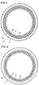
- Figure 1 is a transverse cross-sectional view showing a tube for fuel transportation according to one example of the present invention.
- Figure 2 is a transverse cross-sectional view showing a tube for fuel transportation according to another example of the present invention.
- Figure 1 is a transverse cross-sectional view showing a tube 1 for fuel transportation according to an example of the present invention.
- the tube 1 for fuel transportation has a multilayer structure including five layers: an innermost layer 10 , an adhesive layer 11 , a middle layer 12 , an adhesive layer 13 , and an outer layer 14 (listed from the inside).
- the tube 1 can be fabricated by the following method.
- Five extruders namely, one for the formation of the innermost layer 10 , one for the formation of the adhesive layer 11 , one for the formation of the middle layer 12 , one for the formation of the adhesive layer 13 , and one for the formation of the outer layer 14 are disposed around a mold.
- Melted resins are extruded by the respective extruders so as to be led through slits in the mold, the resins being layered upon one another. Thereafter, the melted resins are discharged at one end of the mold.
- the melted tube having a five-layer structure is adjusted while being cooled in a sizing bath so as to have predetermined dimensions.
- the present invention encompasses, in addition to the above-described tube 1 having a five-layer structure, a tube 1 for fuel transportation having a multilayer structure including four layers and not including the adhesive layer 13 , as shown in Figure 2 .
- This four-layer tube 1 can be fabricated by the same method by which the tube 1 shown in Figure 1 is fabricated except for using four extruders, instead of five.
- the resins included in the tube are conveniently formed in a temperature range of about 150°C to about 320°C, and more preferably about 190°C to about 280°C.
- the present invention does not intend to provide any particular limitation as to the dimensions of either tube 1 for fuel transportation.
- the preferred thicknesses of the layers may be as follows: the innermost layer 10 : 0.1 to 0.3 mm, the adhesive layer 11 : 0.02 to 0.1 mm, the middle layer 12 : 0.05 to 0.2 mm, the adhesive layer 13 : 0.02 to 0.1 mm, and the outer layer 14 : 0.3 to 0.8 mm.
- the preferred thicknesses of the layers may be as follows: the innermost layer 10 : 0.05 to 0.2 mm, the adhesive layer 11 : 0.02 to 0.1 mm, the middle layer 12 : 0.05 to 0.2 mm, and the outer layer 14 : 0.5 to 0.85 mm.
- the tube 1 may have a decreased affinity in conjunction with a joint which follows, thus possibly resulting in the disruption of the inner layer by the joint when the tube 1 is connected thereto or during use of the tube 1 . If the thickness of the inner layer 10 is larger than the larger of the above-mentioned ranges, the flexibility of the entire tube 1 may decrease, and the fabrication cost may increase.
- the thickness of the adhesive layer 11 is smaller than the above-mentioned range, it may be difficult to conduct stable molding of the tube 1 , resulting in nonuniform thickness of the respective layers. This may result in nonuniform adhesion between the layers. If the thickness of the adhesive layer 11 is larger than the above-mentioned range, the thicknesses of the innermost layer 10 , the middle layer 12 , and the outer layer 14 should generally be decreased in order to obtain a tube having a predetermined diameter and a predetermined thickness, thus resulting in deviation from the intended tube characteristics according to the present invention.
- the thickness of the middle layer 12 is smaller than the above-mentioned range, sufficient barrier action against fuels may not be obtained. If the thickness of the middle layer 12 is larger than the above-mentioned range, the flexibility of the entire tube 1 may decrease, and the shock resistance of the tube 1 may decrease.
- the thickness of the adhesive layer 13 is smaller than the above-mentioned range, it becomes difficult to conduct stable molding of the tube 1 , leading to nonuniform thickness of the respective layers. This may result in nonuniform adhesion between the layers. If the thickness of the adhesive layer 13 is larger than the above-mentioned range, the thicknesses of the innermost layer 10 , the middle layer 12 , and the outer layer 14 should generally be decreased in order to obtain a tube having a predetermined diameter and a predetermined thickness, thus resulting in deviation from the intended tube characteristics according to the present invention.
- the weather resistance of the tube 1 may decrease.
- the inner layers of the tube 1 may be left vulnerable to impacts from stones flying from the outside, and the entire tube 1 may have insufficient resistance against chemical agents (e.g. antifreezing agents, antirust agents, etc.).
- the thickness of the outer layer 14 is larger than the larger of the above-mentioned range, the thicknesses of the innermost layer 10 and the middle layer 12 should be decreased in order to obtain a tube having a predetermined diameter and a predetermined thickness, thus resulting in deviation from the intended tube characteristics according to the present invention.
- the innermost layer 10 the adhesive layer 11 , the middle layer 12 , the adhesive layer 13 , and the outer layer 14 will be described individually.
- Fluorine type resins e.g. fluorocarbon type resins
- polyamide type resins can be used for the innermost layer 10 .
- the thickness of the innermost layer 10 should preferably account for 5% to 30% of the total thickness of the tube 1 for fuel transportation.
- Fluorine type resins themselves have good corrosion resistance and chemical resistance. Moreover, they have excellent non water-absorbance, friction resistance, non-adhesiveness, self-lubrication, heat resistance, cold resistance, weather resistance, and the like.
- polytetrafluoroethylene has a melt viscosity of 103 to 1012 poise at 380°C, and has poor thermoplastic properties, although categorized as a thermoplastic resin. Therefore, the usual melt molding technique cannot be used for polytetrafluoroethylene.
- fluorine type resins that are thermoplastic and applicable to an extrusion processing are preferably used for the tube for fuel transportation according to the present invention.
- fluorine type resins include: polyvinylidene fluoride resin (hereinafter referred to as PVDF), ethylene-tetrafluoroethylene copolymer resins (hereinafter referred to as ETFE), polyvinyl fluoride resins (hereinafter referred to as PVF), ethylene-chlorotrifluoroethylene copolymer resins (hereinafter referred to as E-CTFE), chlorotrifluoroethylene resins (hereinafter referred to as PCTFE), tetrafluoroethylene-hexafluoropropylene copolymers (hereinafter referred to as FEP), tetrafluoroethylene-perfluoroalcoxyethylene copolymers (hereinafter referred to as PFA), and tetrafluoroethylenehexafluoropropylene-perfluoro
- PVDFs and ETFEs are especially preferable in view of their molding facility and adhesion to other resins.
- a PVDF as mentioned above, is defined to be a homopolymer of vinylidene fluoride or a copolymer of vinylidene with a monomer which is copolymerizable with vinylidene fluoride.
- monomers that are copolymerizable with vinylidene fluoride include vinyl fluoride, tetrafluoroethylene, trifluorochloroethylene, and hexafluoropropylene.
- ETFEs those in which the molar ratio of ethylene to tetrafluoroethylene is in the range of 30/70 to 60/40 are preferable.
- ETFEs may include copolymers with, if necessary, small amounts of other monomers which are copolymerizable therewith.
- Polyamide type resins that are applicable to the present invention are, preferably, linear polyamides having high molecular weights.
- the polyamide may be a homopolyamide, a copolyamide, or a mixture of a homopolyamide and a copolyamide.
- polyamides examples include homopolyamides, copolyamides, or mixtures of homopolyamides and copolyamides having an amide repetition unit represented by the following Formula I or Formula II: - CO - R1 - NH - : I - CO - R2 CONH - R3 - NH : II where R1, R2, and R3 each represent a straight-chain alkylene group.
- those homopolyamides, copolyamides, or mixtures thereof in which the number of amide groups per 100 carbon atoms is in the range of 3 to 30, and more preferably in the range of 4 to 25, are preferable as the polyamide type resins to be used in the present invention.
- Examples of preferred homopolyamides include polycapramide (nylon 6), poly- ⁇ -aminoheptanic acid (nylon 7), poly- ⁇ -aminononane acid (nylon 9), polyundecaneamide (nylon 11), polylaurinelactam (nylon 12), polyethylene diamineadipamide (nylon 2, 6), polytetramethylene adipamide (nylon 4, 6), polyhexamethylene adipamide (nylon 6, 6), polyhexamethylene sebacamide (nylon 6, 10), polyhexamethylene dodecamide (nylon 6, 12), polyoctamethylene adipamide (nylon 8, 6), polydecamethylene adipamide (nylon 10, 6), polydecamethylene sebacamide (nylon 10, 10), and polydodecamethylene dodecamide (nylon 12, 12).
- Examples of preferred copolyamides include: caprolactam/laurinelactam copolymers, caprolactam/hexamethylene diammoniumadipate copolymers, laurinelactam/hexamethylene diammoniumadipate copolymers, hexamethylene diammoniumadipate/hexamethylene diammoniumsebacate copolymers, ethylene diammoniumadipate/hexamethylene diammoniumadipate copolymers, and caprolactam/hexamethylene diammoniumadipate/hexamethylene diammoniumsebacate copolymers.
- plasticizers such as aromatic sulfone amides, p-hydroxybenzoic acids, and esters, elastomer components having low elasticity, and lactams to the above-mentioned polyamide type resins so as to impart flexibility thereto.
- elastomer components include: ionomer resins, modified polyolefin type resins, thermoplastic polyurethanes, polyetherblockamides, polyesterblockamides, polyetheresteramide type elastomers, polyester type elastomers, modified stylene type thermoplastic elastomers, modified acrylic rubbers, and modified ethylene-propylene rubbers.
- ionomer resins modified polyolefin type resins
- thermoplastic polyurethanes polyetherblockamides
- polyesterblockamides polyetheresteramide type elastomers
- polyester type elastomers polyester type elastomers
- modified stylene type thermoplastic elastomers modified acrylic rubbers
- modified ethylene-propylene rubbers modified ethylene-propylene rubbers.
- the elastomers can be used alone or in combination with one another.
- the above-described materials for the innermost layer 10 may, if necessary, include various additives such as antioxidants, colorants, anti-static agents, conductive materials, flame retarders, reinforcers, stabilizers, and processing aids.
- Polyalkylene naphthalate resins are used for the middle layer 12 .
- the polyalkylene naphthalate resins to be used in the present invention are defined as resins that can be prepared by condensation polymerizing naphthalene dicarboxylic acid or an ester forming derivative thereof with one or more diols generally in the presence of a catalyst and under appropriate reaction conditions.
- naphthalene dicarboxylic acids examples include naphthalene-2,6-dicarboxylic acid, naphthalene-2,7-dicarboxylic acid, and naphthalene-1,5-dicarboxylic acid.
- naphthalene dicarboxylic acids can be used.
- ester forming derivatives examples include naphthalene-2,6-dicarboxylic acid methyl.
- Alkylene glycols are preferably used as the above-mentioned diols.
- alkylene glycols include ethylene glycol, propylene glycol, trimethyl glycol, tetramethylene glycol, pentamethylene glycol, and hexamethylene glycol.
- a particularly preferable polyalkylene naphthalate resin to be used for the present invention is polyethylene naphthalate or polybutylene naphthalate in which naphthalene-2,6-dicarboxylic acid is used as the naphthalate dicarboxylic acid and in which ethylene glycol or 1,4 butanediol is used as the alkylene glycol.
- polybutylene naphthalate is particularly preferably used for the middle layer 12 in terms of barrier action, mechanical strength of the tube, molding facility, and the like.
- preferable polyalkylene naphthalate resins are those which have an inherent viscosity of 0.7 or more, and more preferably an inherent viscosity in the range of 0.9 to 1.5 (the inherent viscosity being measured for a solution of 0.005 g/ml at 35°C with o-chlorophenol used as a solvent, according to ASTM D 2857).
- the polyalkylene naphthalate resin may alternatively be a copolymer in which a part of either the naphthalene dicarboxylic acid as a polyester component or alkylene glycol is substituted by a third component such as other dicarboxylic acids, oxycarboxylic acids, or dioxy compounds.
- dicarboxylic acids examples include naphthalene dicarboxylic acids, terephthalic acids, isophthalic acids, adipic acids, oxalic acids, and diphenyletherdicarboxylic acid.
- oxycarboxylic acids examples include p-oxybenzoic acids and p-oxyethoxybenzoic acids.
- dioxy compounds include dihydric alcohols such as ethylene glycol, propylene glycol, trimethyl glycol, tetramethyl glycol, pentamethylene glycol, hexamethylene glycol, diethylene glycol, bisphenol A and polyalkylene glycols such as polyethylene glycol and polytetramethylene glycol.
- dihydric alcohols such as ethylene glycol, propylene glycol, trimethyl glycol, tetramethyl glycol, pentamethylene glycol, hexamethylene glycol, diethylene glycol, bisphenol A
- polyalkylene glycols such as polyethylene glycol and polytetramethylene glycol.
- the polyalkylene naphthalate resin may, if necessary, melt-include other resins, elastomer components, or compounds having a functional group for improving the adhesion to the other layers, and/or include various additives such as antioxidants, colorants, anti-static agents, flame retarders, reinforcers, stabilizers, and processing aids, as long as the barrier action against fuels of the tube 1 is not reduced.
- the thickness of the middle layer 12 should preferably account for 5% to 20% of the total thickness of the tube 1 for fuel transportation. If the thickness of the middle layer 12 accounts for less than 5% of the total thickness of the tube 1 , the barrier action for fuels decreases. If the thickness of the middle layer 12 accounts for more than 20% of the total thickness of the tube 1 , the flexibility of the entire tube 1 may decrease and the shock resistance of the tube 1 may decrease.
- Polyalkylene naphthalate resins have such characteristics that the breaking strength and breaking stretch thereof increase as the thickness thereof decreases.
- the shock resistance and toughness of the tube 1 become satisfactory by prescribing the thickness thereof to be in the above mentioned range.
- the outer layer 14 may be composed of any thermoplastic resin, and the present invention does not intend to provide any further limitation to the material for the outer layer 14 .
- thermoplastic resins such as polyolefin type resins such as polyamide resins, fluorine type resins, polyester resins, polyurethane type elastomers, polyamide type elastomers, polyester type elastomers, polyacetal type resins, polyethylenes, and polypropylenes.
- the total thickness of the tube 1 should account for 5% to 20% of the outer diameter of the tube 1 , and the thickness of the outer layer 14 should account for 50% to 85% of the total thickness of the tube 1 for the following reasons. If the total thickness of the tube 1 is excessively small, as compared with the outer diameter of the tube 1 , the tube 1 may buckle when bent, thereby interrupting the flow of any fluid that is transported through the tube 1 . Moreover, a joint is generally required in order to connect an end of the tube 1 to another piece of equipment; such a joint requires the tube 1 to have an appropriate thickness.
- the outer layer 14 is required to have such weather resistance, damage-proofness, friction resistance, flexibility, inflammability, colorability, printability, anti-static properties, electrical conductivity, electric insulation, and pressure resistance properties as are appropriate to the particular application of the tube. In order to impart the outer layer 14 with such properties, it is applicable to provide a further layer having such properties on the outer layer 14 .
- a surface layer composed essentially of a resin having a volume specific resistance of about 102 to 109 ⁇ cm may be coated on the outside of the outer layer 14 .
- a reinforcement layer composed essentially of synthetic fibers (such as nylon, vinylon, polyester, and aramid) and/or wires may be woven or wrapped on the outside of the outer layer 14 .
- a reinforcement layer a coating composed of a rubber tube and/or a thermoplastic elastomer, or to wind a coil tube around the tube 1 so as to prevent the tube 1 from being damaged from flying stones, fire, heat of the external air, and the like.
- the adhesive resin to be used as the adhesive layer 11 in the five-layer tube 1 (shown in Figure 1 ) for fuel transportation or in the four-layer tube 1 (shown in Figure 2 ) for fuel transportation, the present invention does not intend to provide any further limitation, although preferably the adhesive resin should be thermally meltable with the innermost layer 10 and the middle layer 12 during coextrusion.
- the adhesive resin to be used as the adhesive layer 11 between the innermost layer 10 and the middle layer 12 may be, preferably, a melted mixture including at least one compound (A) selected from the group consisting of fluorine type resins, flexible fluorine type resins, and fluorine type rubbers and at least one compound (B) selected from the group consisting of crystalline polyester type resins and polyester type elastomers.
- thermoplastic polyurethanes polyamide type elastomers, modified polyolefins, or the like
- the adhesive resin to be used as the adhesive layer 11 between the innermost layer 10 and the middle layer 12 may be, preferably, one or more kinds of thermoplastic polyurethanes, polyetherblockamides, polyesterblockamides, modified polyolefins, polyester copolymers, and polyester type elastomers.
- a composition obtained by melt-mixing a polyamide type resin and a crystalline polyester type resin and/or a polyester type elastomer may alternatively be used as the adhesive resin.
- a composition obtained by melt-mixing one or more kinds of the above-mentioned adhesive resins may preferably be used.
- a composition obtained by melt-mixing with the use of a so-called miscibilizer containing carboxylic acid group, an acid anhydride, a compound having a (meth)acrylic acid or (meth)acrylic acid ester structure, an epoxy compound including glycidyl group or glycidyl ether group, oxazoline group, isocyanate group, amino group, hydroxyl group, and the like may also be preferably used.
- the mixing ratio between the two adhesive resins should be such that sufficient and uniform adhesion is obtained between the innermost layer 10 and the middle layer 12 .
- the mixing ratio between the compound (A) and the compound (B) should be in the range of 80/20 to 30/70 by volume, a preferably in the range of 70/30 to 30/70 by volume. It is preferable to mix, if at all, any of the above-mentioned thermoplastic polyurethanes, polyamide type elastomers, modified polyolefins, and miscibilizers in a ratio, by volume, of 30% or less based on the mixture.
- the mixing ratio between the polyamide type resin and the crystalline polyester type resin and/or the polyester type elastomer should be in the range of 70/30 to 30/70 by volume, an preferably in the range of 60/40 to 40/60 by volume.
- a miscibilizer it is preferable to mix the miscibilizer in a ratio, by volume, of 20% or less based on the mixture.
- the thickness of the adhesive layer 11 should preferably account for 2% to 10% of the total thickness of the tube 1 .
- the thickness of the adhesive layer 11 accounts for less than 2% of the total thickness of the tube 1 , it becomes difficult to conduct stable molding of the tube 1 , leading to nonuniform thickness of the respective layers. This may result in nonuniform adhesion between the layers 10 and 12 . If the thickness of the adhesive layer 11 accounts for more than 10%, the thicknesses of the innermost layer 10 , the middle layer 12 , and the outer layer 14 must be decreased in order to obtain a tube having a predetermined diameter and a predetermined thickness, thus resulting in deviation from the intended tube characteristics according to the present invention.
- the adhesive resin to be used as the adhesive layer 13 in the five-layer tube 1 (shown in Figure 1 ) for fuel transportation does not intend to provide any further limitation although preferably the adhesive resin should be thermally meltable with the middle layer 12 and the outer layer 14 during coextrusion.
- the adhesive resin to be used for the adhesive layer 13 may be, for example, one or more kinds of thermoplastic polyurethanes, polyetherblockamides, polyesterblockamides, modified polyolefins, polyester copolymers, and polyester type elastomers.
- the thickness of the adhesive layer 13 should preferably account for 2% to 10% of the total thickness of the tube 1 .
- the thickness of the adhesive layer 13 accounts for less than 2% of the total thickness of the tube 1 , it becomes difficult to conduct stable molding of the tube 1 , leading to nonuniform thickness of the respective layers. This may result in nonuniform adhesion between the layers 10 and 12 . If the thickness of the adhesive layer 13 accounts for more than 10%, the thicknesses of the innermost layer 10 , the middle layer 12 , and the outer layer 14 must be decreased in order to obtain a tube having a predetermined diameter and a predetermined thickness, thus resulting in deviation from the intended tube characteristics according to the present invention.
- the tube 1 may be configurated as a four-layer tube for fuel transportation.
- the tube for fuel transportation having the above-mentioned multilayer structure may be fabricated by a known coextrusion method, an extrusion coating method, or the like.
- the tube can be efficiently fabricated by a coextrusion method with the use of a plurality of extruders and a tube die for multilayer composites, the number of the extruders corresponding to the configuration of the tube.
- a tube for fuel transportation which includes an innermost layer composed essentially of a fluorine type resin or a polyamide type resin, a middle layer composed essentially of a polyalkylene naphthalate resin, and an outer layer composed essentially of a thermoplastic resin, the layers being bonded to form an integral four-layer (in the case no adhesive layer is provided between the middle layer and the outer layer) or five-layer (in the case where an adhesive layer is provided between the innermost layer and the middle layer and another adhesive layer is provided between the middle layer and the outer layer) tube. Further layers may be present depending on the particular application for the tube.
- the resultant tube has, as will be described later with reference to the examples of the present invention, excellent barrier action against fuels and excellent kink-proofness.
- sample liquids I and II were provided in a tube having an outer diameter of 8 mm, an inner diameter of 6 mm, and a length of 1000 mm, and left in an oven heated at 60°C or in an oven heated at 40°C, whereby the temporal decrease in the weight of the sample liquid I or II was obtained.
- the decrease in the weight of either sample liquid was divided by the outer surface area of the tube and was calculated to give a value in the form of g/m2/day. The calculated value was defined as the transmission rate.
- Sample liquid I (Fuel C): A mixture of a reagent-class toluene and a reagent-class isooctane mixed at a ratio of 1/1 by volume.
- Sample liquid II A mixture of Fuel C and methanol mixed at a ratio of 85/15 by volume.
- a tube having an outer diameter of 8 mm and an inner diameter of 6 mm was bent in a semi-circle shape, with the radius of the semi-circle being gradually decreased until the tube kinked.
- the value of the radius obtained immediately before the tube kinked was used as an indicator of the kink-proofness of the tube. Accordingly, a tube having a smaller radius obtained immediately before the generation of a kink is regarded to be more kink-proof.
- This tube 1 includes an innermost layer 10 (thickness: 0.2 mm) composed essentially of nylon 11, an adhesive layer 11 (thickness: 0.05 mm) composed essentially of a thermoplastic polyurethane, a middle layer 12 (thickness: 0.1 mm) composed essentially of polybutylene naphthalate, an adhesive layer 13 (thickness: 0.05 mm) composed essentially of a thermoplastic polyurethane, and an outer layer 14 (thickness: 0.6 mm) composed essentially of nylon 11.
- This tube 1 was obtained as follows. Each of nylon 11, polybutylene naphthalate, and a thermoplastic polyurethane was inserted into a corresponding one of three extruders. The nylon 11, the polybutylene naphthalate, and the thermoplastic polyurethane were plasticized while being processed at respective temperature ranges of 220°C to 240°C, 230°C to 250°C, and 190°C to 210°C. Thereafter, a three-material five-layer tube having an outer diameter of 8 mm and an inner diameter of 6 mm was extruded from a three-material five-layer tube die maintained at 245°C.
- This tube 1 includes an innermost layer 10 (thickness: 0.2 mm) composed essentially of nylon 11, an adhesive layer 11 (thickness: 0.05 mm) composed essentially of a modified polyolefin, a middle layer 12 (thickness: 0.1 mm) composed essentially of polybutylene naphthalate, an adhesive layer 13 (thickness: 0.05 mm) composed essentially of a modified polyolefin, and an outer layer 14 (thickness: 0.6 mm) composed essentially of nylon 11.
- This tube 1 was obtained by the same manner by which the tube 1 of Example 1 was obtained except that the adhesive layers 11 and 13 were formed at a temperature range of 230°C to 240°C.
- This tube 1 includes an innermost layer 10 (thickness: 0.2 mm) composed essentially of nylon 11, an adhesive layer 11 (thickness: 0.05 mm) composed essentially of a mixture of a thermoplastic polyurethane and a polyester type elastomer mixed at a ratio of 5/5 by volume, a middle layer 12 (thickness: 0.1 mm) composed essentially of polybutylene naphthalate, an adhesive layer 13 (thickness: 0.05 mm) composed essentially of a mixture of a thermoplastic polyurethane and a polyester type elastomer mixed at a ratio of 5/5 by volume, and an outer layer 14 (thickness: 0.6 mm) composed essentially of nylon 11.
- This tube 1 was obtained by the same manner by which the tube 1 of Example 1 was obtained except that the adhesive layers 11 and 13 were formed at a temperature range of 210°C to 230°C.
- This tube 1 includes an innermost layer 10 (thickness: 0.2 mm) composed essentially of nylon 11, an adhesive layer 11 (thickness: 0.05 mm) composed essentially of a mixture of a polyetherblockamide and a polyester type elastomer mixed at a ratio of 5/5 by volume, a middle layer 12 (thickness: 0.1 mm) composed essentially of polybutylene naphthalate, an adhesive layer 13 (thickness: 0.05 mm) composed essentially of a mixture of a polyetherblockamide and a polyester type elastomer mixed at a ratio of 5/5 by volume, and an outer layer 14 (thickness: 0.6 mm) composed essentially of nylon 11.
- This tube 1 was obtained by the same manner by which the tube 1 of Example 1 was obtained except that the adhesive layers 11 and 13 were formed at a temperature range of 230°C to 240°C.
- This tube 1 has the same configuration as that of the tube 1 of Example 4 except that the middle 12 was formed by using polyethylene naphthalate instead of polybutylene naphthalate.
- This tube 1 was obtained by the same manner by which the tube 1 of Example 4 was obtained except that the middle layer 12 was formed at a temperature range of 280°C to 300°C, and the three-material five-layer tube die was heated at a temperature range of 270°C to 280°C.
- This tube 1 includes an innermost layer 10 (thickness: 0.2 mm) composed essentially of nylon 11, an adhesive layer 11 (thickness: 0.05 mm) composed essentially of a mixture of nylon 11, polybutylene terephthalate, and a thermoplastic polyurethane mixed at a ratio of 4/4/1 by volume, a middle layer 12 (thickness: 0.1 mm) composed essentially of polybutylene naphthalate, and an outer layer 14 (thickness: 0.65 mm) composed essentially of a polyester type elastomer.
- This tube 1 was obtained as follows. Each of the resins used for the innermost layer 10 , the adhesive layer 11 , the middle layer 12 , and the outer layer 14 was inserted into a corresponding one of four extruders. The resins were plasticized while being processed at respective temperature ranges of 210°C to 240°C, 210°C to 240°C, 230°C to 250°C, and 220°C to 240°C. Thereafter, a four-material four-layer tube having an outer diameter of 8 mm and an inner diameter of 6 mm was extruded from a four-material four-layer tube die maintained at 245°C.
- This tube 1 includes an innermost layer 10 (thickness: 0.2 mm) composed essentially of nylon 11, an adhesive layer 11 (thickness: 0.05 mm) composed essentially of a mixture of nylon 11, a polyester type elastomer, and a modified polyolefin mixed at a ratio of 5/5/1 by volume, a middle layer 12 (thickness: 0.1 mm) composed essentially of polybutylene naphthalate, an adhesive layer 13 (thickness: 0.05 mm) composed essentially of a mixture of nylon 11, a polyester type elastomer, and a modified polyolefin mixed at a ratio of 5/5/1 by volume, and an outer layer 14 (thickness: 0.6 mm) composed essentially of nylon 11.
- This tube 1 was obtained as follows. Each of nylon 11, polybutylene naphthalate, and a mixture of nylon 11, a polyester type elastomer, and a modified polyolefin mixed at a ratio of 5/5/1 by volume was inserted into a corresponding one of three extruders. The nylon 11, the polybutylene naphthalate, and the mixture of nylon 11, the polyester type elastomer, and the modified polyolefin were plasticized while being processed at respective temperature ranges of 220°C to 240°C, 240°C to 260°C, and 230°C to 250°C. Thereafter, a three-material five-layer tube having an outer diameter of 8 mm and an inner diameter of 6 mm was extruded from a three-material five-layer tube die maintained at 260°C.
- the transmission rate and the kink-proofness were measured for the tubes 1 of Examples 1 to 7.
- the measurement results are shown in Table 1 along with the configurations of the tubes 1 .
- a larger transmission rate indicates a lower barrier action against fuels of the tube.
- This tube 1 includes an innermost layer 10 (thickness: 0.1 mm) composed essentially of polyvinylidene fluoride (PVDF), an adhesive layer 11 (thickness: 0.05 mm) composed essentially of a mixture of PVDF, polybutylene terephthalate, and a thermoplastic polyurethane mixed at a ratio of 4/4/1 by volume, a middle layer 12 (thickness: 0.1 mm) composed essentially of polybutylene naphthalate, an adhesive layer 13 (thickness: 0.05 mm) composed essentially of a thermoplastic polyurethane, and an outer layer 14 (thickness: 0.6 mm) composed essentially of nylon 11.
- PVDF polyvinylidene fluoride
- an adhesive layer 11 thickness: 0.05 mm
- a middle layer 12 thickness: 0.1 mm
- an adhesive layer 13 thickness: 0.05 mm
- an outer layer 14 thickness: 0.6 mm
- This tube 1 was obtained as follows. Each of the resins used for the innermost layer 10 , the adhesive layer 11 , the middle layer 12 , the adhesive layer 13 , and the outer layer 14 was inserted into a corresponding one of five extruders. The resins were plasticized while being processed at respective temperature ranges of 200°C to 220°C, 200°C to 220°C, 230°C to 250°C, 190°C to 210°C, and 220°C to 240°C. Thereafter, a five-material five-layer tube having an outer diameter of 8 mm and an inner diameter of 6 mm was extruded from a five-material five-layer tube die maintained at 245°C.
- This tube 1 includes an innermost layer 10 (thickness: 0.1 mm) composed essentially of a polyvinylidene fluoridehexafluoropropylene copolymer, an adhesive layer 11 (thickness: 0.05 mm) composed essentially of a flexible fluorine type resin, a polyester type elastomer, and a thermoplastic polyurethane mixed at a ratio of 5/4/1 by volume, a middle layer 12 (thickness: 0.1 mm) composed essentially of polybutylene naphthalate, an adhesive layer 13 (thickness: 0.05 mm) composed essentially of a thermoplastic polyurethane, and an outer layer 14 (thickness: 0.7 mm) composed essentially of nylon 11.
- This tube 1 was obtained by the same manner by which the tube 1 of Example 8 was obtained except that the innermost layer 10 was formed at a temperature range of 190°C to 210°C.
- This tube 1 includes an innermost layer 10 (thickness: 0.1 mm) composed essentially of an ethylene-tetrafluoroethylene copolymer (ETFE), an adhesive layer 11 (thickness: 0.05 mm) composed essentially of a flexible fluorine type resin, a polyester type elastomer, and a modified polyolefin mixed at a ratio of 2/5/3 by volume, a middle layer 12 (thickness: 0.1 mm) composed essentially of polybutylene naphthalate, and an outer layer 14 (thickness: 0.75 mm) composed essentially of a polyester type elastomer.
- an innermost layer 10 (thickness: 0.1 mm) composed essentially of an ethylene-tetrafluoroethylene copolymer (ETFE)
- an adhesive layer 11 thickness: 0.05 mm
- a middle layer 12 thickness: 0.1 mm
- an outer layer 14 thickness: 0.75 mm
- This tube 1 was obtained by using four extruders and a four-material four-layer tube die as in Example 6, the innermost layer 10 and the adhesive layer 11 being formed at respective temperature ranges of 230°C to 260°C and 220°C to 240°C, and maintaining the tube die at 250°C. Thus, the four-material four-layer tube 1 was obtained.
- This tube 1 includes an innermost layer 10 (thickness: 0.1 mm) composed essentially of an ethylene-tetrafluoroethylene copolymer (ETFE), an adhesive layer 11 (thickness: 0.05 mm) composed essentially of ETFE, polybutylene terephthalate, and ethyleneglycidyl methacrylate mixed at a ratio of 5/5/1 by volume, a middle layer 12 (thickness: 0.1 mm) composed essentially of polybutylene naphthalate, an adhesive layer 13 (thickness: 0.05 mm) composed essentially of nylon 11, a polyester type elastomer, and a modified polyolefin mixed at a ratio of 5/5/1 by volume, and an outer layer 14 (thickness: 0.6 mm) composed essentially of nylon 11.
- an innermost layer 10 thickness: 0.1 mm
- ETFE ethylene-tetrafluoroethylene copolymer
- an adhesive layer 11 thickness: 0.05 mm
- a middle layer 12
- This tube 1 was obtained as follows. Each of the resins used for the innermost layer 10 , the adhesive layer 11 , the middle layer 12 , the adhesive layer 13 , and the outer layer 14 was inserted into a corresponding one of five extruders. The resins were plasticized while being processed at respective temperature ranges of 270°C to 290°C, 250°C to 270°C, 240°C to 260°C, 230°C to 250°C, and 220°C to 240°C. Thereafter, a five-material five-layer tube having an outer diameter of 8 mm and an inner diameter of 6 mm was extruded from a five-material five-layer tube die maintained at 260°C.
- the transmission rate and the kink-proofness were measured for the tubes 1 of Examples 8 to 11.
- the measurement results are shown in Table 2 along with the configurations of the tubes 1 .
- the tube of Comparative Example 1 is a single layer tube (thickness: 1 mm) composed essentially of nylon 11.
- the tube of Comparative Example 2 is a single layer tube (thickness: 1 mm) composed essentially of PVDF.
- the tube of Comparative Example 3 is a single layer tube (thickness: 1 mm) composed essentially of ETFE.
- the tube of Comparative Example 4 is a single layer tube (thickness: 1 mm) composed essentially of a polybutylene terephthalate resin.
- the tube of Comparative Example 5 is a single layer tube (thickness: 1 mm) composed essentially of a polyethylene terephthalate resin.
- the tube of Comparative Example 6 includes an innermost layer 10 (thickness: 0.7 mm) composed essentially of a polybutylene terephthalate resin and an outer layer 14 (thickness: 0.3 mm) composed essentially of nylon 12.
- the tube of Comparative Example 7 is a single layer tube (thickness: 1 mm) composed essentially of cyclohexanedimethanol-ethyleneglycol-terephthalic acid copolymer.
- the tube of Comparative Example 8 includes an innermost layer 10 (thickness: 0.2 mm) composed essentially of nylon 12, a middle layer 12 (thickness: 0.2 mm) composed essentially of polybutylene terephthalate and an outer layer 14 (thickness: 0.6 mm) composed essentially of nylon 12.
- the tube of Comparative Example 9 includes an innermost layer 10 (thickness: 0.1 mm) composed essentially of nylon 12, a middle layer 12 (thickness: 0.15 mm) composed essentially of a mixture of a polybutylene terephthalate resin, nylon 12, and triphenylene phosphite mixed at a ratio of 50/50/0.1 by weight, and an outer layer 14 (thickness: 0.75 mm) composed essentially of nylon 12.
- the tube of Comparative Example 10 includes an innermost layer 10 (thickness: 0.1 mm) composed essentially of nylon 12, a middle layer 12 (thickness: 0.15 mm) composed essentially of a mixture of a polybutylene terephthalate resin and anhydride maleic acid modified EPM mixed at a ratio of 80/20 by weight, and an outer layer 14 (thickness: 0.75 mm) composed essentially of nylon 12.
- the tube of Comparative Example 11 includes an innermost layer 10 (thickness: 0.2 mm) composed essentially of nylon 12, a middle layer 12 (thickness: 0.2 mm) composed essentially of a mixture of a polybutylene terephthalate resin and an isocyanurate of isophorone diisocyanate mixed at a ratio of 90/10 by weight, and an outer layer 14 (thickness: 0.6 mm) composed essentially of nylon 12.
- the tube of Comparative Example 12 includes an innermost layer 10 (thickness: 0.2 mm) composed essentially of nylon 11, an adhesive layer 11 (thickness: 0.05 mm) composed essentially of a thermoplastic polyurethane, a middle layer 12 (thickness: 0.1 mm) composed essentially of polybutylene terephthalate, an adhesive layer 13 (thickness: 0.05 mm) composed essentially of a thermoplastic polyurethane, and an outer layer 14 (thickness: 0.6 mm) composed essentially of nylon 11.
- the tube of Comparative Example 13 includes an innermost layer 10 (thickness: 0.2 mm) composed essentially of nylon 11, a middle layer 12 (thickness: 0.1 mm) composed essentially of polybutylene naphthalate, and an outer layer 14 (thickness: 0.6 mm) composed essentially of nylon 11.
- the tube of Comparative Example 14 includes an innermost layer 10 (thickness: 0.1 mm) composed essentially of PVDF, an adhesive layer 11 (thickness: 0.05 mm) composed essentially of PVDF, polybutylene terephthalate, and a thermoplastic polyurethane mixed at a ratio of 4/4/1 by volume, a middle layer 12 (thickness: 0.1 mm) composed essentially of polybutylene terephthalate, an adhesive layer 13 (thickness: 0.05 mm) composed essentially of a thermoplastic polyurethane, and an outer layer 14 (thickness: 0.7 mm) composed essentially of nylon 11.
- the tube of Comparative Example 15 includes an innermost layer 10 (thickness: 0.1 mm) composed essentially of PVDF, a middle layer 12 (thickness: 0.1 mm) composed essentially of polybutylene naphthalate, and an outer layer 14 (thickness: 0.8 mm) composed essentially of nylon 11.
- the single tubes of all the Comparative Examples but Comparative Example 13 have a large transmission rate for the fuels, indicative of small barrier action when compared with those of the tubes 1 of Examples 1 to 11 made in accordance with the present invention.
- the common polyester resins used in Comparative Examples 4 to 7 have transmission rates which are several dozen times as large as the transmission rates of the multi-layer tubes 1 according to the present invention incorporating polybutylene naphthalate resins.
- polybutylene naphthalate has remarkably excellent barrier action against fuels.
- the following is apparent from comparison between the tubes 1 of Examples 1 to 7 and the tube of Comparative Example 13.
- the tubes 1 of Examples 1 to 7 and the tube of Comparative Example 13 have only a small difference in barrier action for the fuels.
- the tube of Comparative Example 13 has considerably lower kink-proofness. Accordingly, the kink-proofness of the tubes 1 according to the present invention is remarkably improved by the incorporation of the adhesive layers 11 and 13 .
- the tube of Comparative Example 14 has a large transmission rate for the fuels, indicative of several dozen times smaller barrier action against both Fuel C (Sample liquid I) and the alcohol-containing mixed fuel (Sample liquid II) than the barrier action of the tubes 1 of Example 8.
- polybutylene naphthalate provides far greater advantages than polybutylene terephthalate as a material for the middle layer 12 .
- the tube 1 of Example 8 and the tube of Comparative Example 15 have only a small difference in barrier action against the fuels.
- the tube of Comparative Example 15 has considerably lower kink-proofness.
- the tube of Example 8 has improved kink-proofness. Accordingly, the kink-proofness of the tubes 1 according to the present invention is remarkably improved by the incorporation of the adhesive layers 11 and 13 .
Landscapes
- Engineering & Computer Science (AREA)
- General Engineering & Computer Science (AREA)
- Mechanical Engineering (AREA)
- Laminated Bodies (AREA)
- Rigid Pipes And Flexible Pipes (AREA)
Applications Claiming Priority (3)
| Application Number | Priority Date | Filing Date | Title |
|---|---|---|---|
| JP19261093 | 1993-08-03 | ||
| JP192610/93 | 1993-08-03 | ||
| JP19261093 | 1993-08-03 |
Publications (2)
| Publication Number | Publication Date |
|---|---|
| EP0637509A1 true EP0637509A1 (fr) | 1995-02-08 |
| EP0637509B1 EP0637509B1 (fr) | 2002-10-23 |
Family
ID=16294128
Family Applications (1)
| Application Number | Title | Priority Date | Filing Date |
|---|---|---|---|
| EP94305715A Expired - Lifetime EP0637509B1 (fr) | 1993-08-03 | 1994-08-02 | Tube pour transport d'essence |
Country Status (4)
| Country | Link |
|---|---|
| US (2) | US6089278A (fr) |
| EP (1) | EP0637509B1 (fr) |
| KR (1) | KR100303858B1 (fr) |
| DE (1) | DE69431579T2 (fr) |
Cited By (31)
| Publication number | Priority date | Publication date | Assignee | Title |
|---|---|---|---|---|
| EP0686797A1 (fr) * | 1994-05-21 | 1995-12-13 | Hüls Aktiengesellschaft | Tuyau multicouche en matière plastique ayant une bonne adhésion |
| WO1997011300A1 (fr) * | 1995-09-23 | 1997-03-27 | Siebe Fluid Systems Gmbh | Conduite flexible d'eau de refroidissement pour vehicules automobiles |
| EP0767190A1 (fr) * | 1995-10-04 | 1997-04-09 | Ems-Inventa Ag | Agent adhésif à base de polyamide |
| GB2301417B (en) * | 1994-03-04 | 1997-12-03 | Aeroquip Corp | A tube suitable for use with fuel systems for motor vehicles |
| WO1998000662A3 (fr) * | 1996-07-01 | 1998-05-07 | Stanley Aviation Corp | Vehicule ameliore comportant des appareils de transport de fluide resistant aux contraintes du gel |
| WO1998029245A2 (fr) * | 1996-12-31 | 1998-07-09 | The Dow Chemical Company | Structures stratifiees pour contenants a combustible |
| WO1998043806A1 (fr) * | 1997-03-29 | 1998-10-08 | Hewing Gmbh | Tuyau en plastique a plusieurs couches |
| EP0912330A1 (fr) * | 1996-05-23 | 1999-05-06 | Eagle-Picher Industries, Inc. | Conduites laminees de retour de combustible et de vapeur |
| WO1999024242A1 (fr) * | 1997-11-06 | 1999-05-20 | Alliedsignal Inc. | Structures multicomposant a pouvoir d'adhesion accru |
| WO1999024256A1 (fr) * | 1997-11-06 | 1999-05-20 | Alliedsignal Inc. | Films multicouche en poly(alkylene naphthalate) halopolymere arretant les ultraviolets |
| WO1999052975A1 (fr) * | 1998-04-09 | 1999-10-21 | Minnesota Mining And Manufacturing Company | Compositions multicouches comprenant un polymere fluore |
| FR2781273A1 (fr) * | 1998-07-16 | 2000-01-21 | Rasmussen Gmbh | Canalisation fluidique pour des carburants ou des vapeurs de carburants |
| EP0982122A2 (fr) * | 1998-08-26 | 2000-03-01 | Degussa-Hüls Aktiengesellschaft | Structure multicouche à propriété de barrière |
| US6156400A (en) * | 1998-04-09 | 2000-12-05 | 3M Innovative Properties Company | Multi-layer compositions comprising a fluoropolymer |
| FR2794837A1 (fr) * | 1999-06-10 | 2000-12-15 | Atofina | Tube pour le transport d'essence |
| EP1208969A2 (fr) * | 2000-11-23 | 2002-05-29 | Rasmussen GmbH | Tube multicouche |
| EP1249654A1 (fr) * | 2001-04-12 | 2002-10-16 | Rasmussen GmbH | Conduite multicouche |
| EP1249336A3 (fr) * | 2001-04-10 | 2003-01-02 | Rasmussen GmbH | Tube multicouche pour fluides contenant des hydrocarbones |
| EP1418374A1 (fr) * | 2001-07-19 | 2004-05-12 | Nitta Moore Company | Tube resistant a la chaleur |
| EP1522780A1 (fr) * | 2003-09-08 | 2005-04-13 | Nissan Motor Company, Limited | tuyau en résine |
| EP1559537A1 (fr) | 2004-01-29 | 2005-08-03 | TI Automotive (Fuldabrück) GmbH | Tuyau multicouche en plastique à propriété barrière |
| EP1671781A1 (fr) * | 2004-12-10 | 2006-06-21 | Sanoh Kogyo Kabushiki Kaisha | Tube plastique multicouche |
| EP2008804A1 (fr) * | 2007-06-28 | 2008-12-31 | Nissan Motor Co., Ltd. | Tuyau multicouche |
| USD621068S1 (en) | 2002-03-01 | 2010-08-03 | 3Form, Inc. | Architectural panel with thatch reed design |
| BE1018516A3 (nl) * | 2009-03-30 | 2011-02-01 | Tekni Plex Europ Nv Nv | Werkwijze voor het vervaardigen van een meerlagige filmstructuur op basis van fluorpolymeren, en filmstructuur op deze wijze vervaardigd, alsook haar gebruik in de fotovolta¤sche toepassingen. |
| US8221890B2 (en) | 2004-10-07 | 2012-07-17 | Evonik Degussa Gmbh | Multilayer composite having a polyester layer and a protective layer |
| US8241714B2 (en) | 2004-09-01 | 2012-08-14 | 3Form, Inc. | Architectural panels with objects embedded in resin interlayer |
| USD691289S1 (en) | 2012-09-05 | 2013-10-08 | 3Form, Inc. | Panel with cut and aligned thatch interlayer |
| WO2014075773A1 (fr) * | 2012-11-16 | 2014-05-22 | Rehau Ag + Co | Tuyau flexible pourvu d'une paroi multicouche |
| EP3299174A4 (fr) * | 2015-05-20 | 2019-01-02 | Hakko Corporation | Tube d'alimentation en encre |
| EP2851190B1 (fr) * | 2013-09-24 | 2020-05-20 | Hanil Tube Corporation | Tube de transfert d'hydrogène |
Families Citing this family (48)
| Publication number | Priority date | Publication date | Assignee | Title |
|---|---|---|---|---|
| US6378562B1 (en) * | 1992-04-14 | 2002-04-30 | Itt Industries, Inc. | Multi-layer tubing having electrostatic dissipation for handling hydrocarbon fluids |
| DE69431579T2 (de) * | 1993-08-03 | 2003-03-27 | Nitta Moore Co Ltd | Kraftstofftransportschlauch |
| DE19507025A1 (de) * | 1995-03-01 | 1996-09-05 | Huels Chemische Werke Ag | Mehrschichtrohr mit elektrisch leitfähiger Innenschicht |
| CN1061592C (zh) * | 1995-06-26 | 2001-02-07 | 乌波诺尔创新股份公司 | 管状产品和挤压设备及其方法 |
| JP2000154890A (ja) * | 1998-11-18 | 2000-06-06 | Tokai Rubber Ind Ltd | 燃料配管用チューブ |
| US6279615B1 (en) * | 1999-09-03 | 2001-08-28 | Tokai Rubber Industries, Ltd. | Fuel hose |
| FR2812929B1 (fr) * | 2000-08-11 | 2004-01-09 | Nobel Plastiques | Tube multicouche en matiere plastique pour fluides utilises dans les vehicules automobiles |
| JP2002156075A (ja) * | 2000-09-05 | 2002-05-31 | Tokai Rubber Ind Ltd | 燃料ホース |
| US7691470B2 (en) | 2001-03-05 | 2010-04-06 | 3Form | Laminate structure with polycarbonate sheets |
| DE60213962T2 (de) * | 2001-03-26 | 2007-08-30 | Parker-Hannifin Corp., Cleveland | Röhrenförmige polymere verbundwerkstoffe für rohr- und schlauchkonstruktionen |
| JP2003033983A (ja) * | 2001-05-15 | 2003-02-04 | Tokai Rubber Ind Ltd | 燃料ホース |
| US6591871B2 (en) * | 2001-09-13 | 2003-07-15 | Dayco Products, Llc | Low permeation polybutylene terephthalate and polybutylene naphthalate fuel and vapor tubes |
| FR2832781B1 (fr) * | 2001-11-27 | 2004-04-16 | Nobel Plastiques | Conduite multicouche pour le transport de fluides automobiles |
| JP2003287164A (ja) * | 2002-01-24 | 2003-10-10 | Tokai Rubber Ind Ltd | 燃料用ホース |
| JP2003287165A (ja) * | 2002-01-24 | 2003-10-10 | Tokai Rubber Ind Ltd | 燃料用ホース |
| DE10203626B4 (de) * | 2002-01-30 | 2004-01-08 | Veritas Ag | Mehrschichtiges Rohr bzw. Schlauch |
| US20030145896A1 (en) * | 2002-02-06 | 2003-08-07 | Saint-Gobain Performance Plastics Corporation | Coiled laminated air brake tubing |
| FR2838501B1 (fr) * | 2002-04-15 | 2005-07-01 | Nobel Plastiques | Tube de transport d'un fluide automobile |
| JP3606280B2 (ja) * | 2002-07-16 | 2005-01-05 | 日産自動車株式会社 | 樹脂製チューブ及び燃料系配管用チューブ |
| US6659512B1 (en) * | 2002-07-18 | 2003-12-09 | Hewlett-Packard Development Company, L.P. | Integrated circuit package employing flip-chip technology and method of assembly |
| JP2004090405A (ja) * | 2002-08-30 | 2004-03-25 | Tokai Rubber Ind Ltd | 自動車用燃料系ホース |
| FR2845453B1 (fr) * | 2002-10-07 | 2004-11-26 | Nobel Plastiques | Conduite pour le transport de fluides contenant de l'hydrogene |
| JP2004169851A (ja) * | 2002-11-21 | 2004-06-17 | Sanoh Industrial Co Ltd | 多層チューブ |
| JP2004239429A (ja) * | 2003-01-16 | 2004-08-26 | Tokai Rubber Ind Ltd | 自動車用燃料系ホース |
| US6880862B2 (en) * | 2003-04-10 | 2005-04-19 | Dayco Products, Llc | Conductive tubular insert for a fuel transport system, and method |
| WO2004098880A1 (fr) * | 2003-05-12 | 2004-11-18 | Daikin Industries, Ltd. | Stratifie |
| KR100826374B1 (ko) | 2004-04-13 | 2008-05-02 | 다이킨 고교 가부시키가이샤 | 클로로트리플루오로에틸렌 공중합체 |
| TW200538472A (en) | 2004-04-13 | 2005-12-01 | Daikin Ind Ltd | The component of fluid transporter |
| FR2874987B1 (fr) * | 2004-09-08 | 2006-12-01 | Nobel Plastiques Soc Par Actio | Conduite multicouche pa/po-pa/tpe-e |
| US20060057391A1 (en) * | 2004-09-15 | 2006-03-16 | Anthony Bonnet | Structure comprising at least one polyethylene layer and at least one layer of barrier polymer |
| FR2875169B1 (fr) * | 2004-09-15 | 2008-07-04 | Arkema Sa | Structure comprenant au moins une couche de polyethylene et au moins une couche de polymere barriere |
| FR2879281B1 (fr) * | 2004-12-13 | 2007-02-16 | Nobel Plastiques Soc Par Actio | Tube fluoropolymere/evoh/pa modifie |
| FR2886708B1 (fr) * | 2005-06-02 | 2007-08-17 | Arkema Sa | Utilisation de polymere fluore modifie pour le transport d'eau ou de gaz |
| JP2007261078A (ja) * | 2006-03-28 | 2007-10-11 | Tokai Rubber Ind Ltd | 燃料用ホース |
| FR2904867B1 (fr) * | 2006-08-08 | 2008-09-19 | Arkema France | Tube multicouche pour le transport d'eau ou de gaz |
| EP2150407A4 (fr) | 2007-05-08 | 2013-03-06 | Hunter Douglas Ind Switzerland | Système de couleur à plusieurs variables avec application de texture |
| FR2918067B1 (fr) * | 2007-06-27 | 2011-07-01 | Arkema France | Materiau composite comprenant des nanotubes disperses dans une matrice polymerique fluroree. |
| US7866348B2 (en) * | 2008-05-01 | 2011-01-11 | Saint-Gobain Performance Plastics Corporation | Multi-layered fuel tubing |
| JP5551379B2 (ja) * | 2009-03-31 | 2014-07-16 | 帝人株式会社 | 自動車燃料部品用の熱可塑性樹脂材料 |
| WO2014047627A1 (fr) * | 2012-09-24 | 2014-03-27 | Eaton Corporation | Tubulure de frein à air et compositions pour sa fabrication |
| EP2772354B1 (fr) * | 2013-03-01 | 2018-12-05 | TI Automotive (Fuldabrück) GmbH | Conduite de carburant multicouche |
| JP2016089810A (ja) * | 2014-11-11 | 2016-05-23 | 株式会社デンソー | 燃料供給装置 |
| EP3069874B1 (fr) * | 2015-03-17 | 2017-07-19 | Evonik Degussa GmbH | Composite multicouches comprenant une couche polyester |
| EP3069875B1 (fr) * | 2015-03-17 | 2017-07-05 | Evonik Degussa GmbH | Composite multicouches comprenant une couche fluoropolymère |
| CN108700227A (zh) * | 2016-02-19 | 2018-10-23 | 株式会社八兴 | 静电消散性树脂管 |
| US10316992B2 (en) * | 2017-06-09 | 2019-06-11 | GM Global Technology Operations LLC | Tubing for fluid cooling systems |
| EP3530454B1 (fr) * | 2018-02-22 | 2020-06-10 | TI Automotive (Fuldabrück) GmbH | Conduite du véhicule automobile multicouche |
| EP3875263A1 (fr) * | 2020-03-06 | 2021-09-08 | TI Automotive (Fuldabrück) GmbH | Conduite du véhicule automobile multicouche |
Citations (6)
| Publication number | Priority date | Publication date | Assignee | Title |
|---|---|---|---|---|
| JPH04224438A (ja) * | 1990-04-04 | 1992-08-13 | Mercedes Benz Ag | 自動車の衝突事故の際の乗客防護装置 |
| EP0509212A2 (fr) * | 1991-04-18 | 1992-10-21 | Hüls Aktiengesellschaft | Tuyau en matière plastique à plusieurs couches |
| DE4137431A1 (de) * | 1991-11-14 | 1993-05-19 | Huels Chemische Werke Ag | Mehrschichtiges kunststoffrohr |
| EP0542185A1 (fr) * | 1991-11-14 | 1993-05-19 | Hüls Aktiengesellschaft | Tuyau multicouche en plastique |
| FR2689956A1 (fr) * | 1992-03-30 | 1993-10-15 | Tokai Rubber Ind Ltd | Tuyau de transport de carburant comportant un tube formé de couches de résine dont une contient du fluor, tube en résine pour ce tuyau et procédé pour sa fabrication. |
| EP0567947A1 (fr) * | 1992-04-30 | 1993-11-03 | Ems-Inventa Ag | Conduite de tuyau ou flexible de plusieurs couches de polymères |
Family Cites Families (17)
| Publication number | Priority date | Publication date | Assignee | Title |
|---|---|---|---|---|
| FR2479528A1 (fr) | 1980-03-26 | 1981-10-02 | Gefitec Sa | Cassette video perfectionnee |
| DE3613188A1 (de) * | 1985-04-19 | 1986-10-23 | Toyoda Gosei Co., Ltd., Haruhi, Aichi | Gummi-schichtstoff |
| US4800129A (en) * | 1987-03-26 | 1989-01-24 | E. I. Du Pont De Nemours And Company | Multi-layer plastic container |
| JPH01159245A (ja) * | 1987-12-16 | 1989-06-22 | Tokai Rubber Ind Ltd | ゴムホース |
| EP0336806A3 (fr) * | 1988-03-21 | 1991-02-27 | Alcatel N.V. | Extrusion simultanée d'un tube tampon à deux couches |
| JPH0733878B2 (ja) * | 1989-05-29 | 1995-04-12 | 東海ゴム工業株式会社 | 冷媒輸送用ホース |
| DE4001125C1 (fr) * | 1989-11-20 | 1990-12-13 | Technoform Caprano + Brunnhofer Kg, 3501 Fuldabrueck, De | |
| KR0170407B1 (ko) * | 1990-09-26 | 1999-03-20 | 모토야마 가즈오 | 기체 및 오일 불투과성 호오스 구조물 |
| JP3136614B2 (ja) * | 1990-12-20 | 2001-02-19 | 東海ゴム工業株式会社 | 燃料配管用チューブ |
| DE4112668A1 (de) * | 1991-04-18 | 1992-10-22 | Huels Chemische Werke Ag | Thermoplastische mehrschichtverbunde |
| US5170011A (en) * | 1991-09-25 | 1992-12-08 | Teleflex Incorporated | Hose assembly |
| DE4138510A1 (de) * | 1991-11-14 | 1993-05-19 | Huels Chemische Werke Ag | Formmassen enthaltend ein polykondensat |
| ES2098422T3 (es) * | 1991-11-14 | 1997-05-01 | Huels Chemische Werke Ag | Compuestos termoplasticos de varias capas. |
| DE4137434A1 (de) * | 1991-11-14 | 1993-05-19 | Huels Chemische Werke Ag | Thermoplastische mehrschichtverbunde |
| DE69311403T2 (de) * | 1992-03-05 | 1997-12-04 | Nitta Moore Co Ltd | Brennstoffübertragendes Rohr |
| DE4215608A1 (de) * | 1992-05-12 | 1993-11-18 | Huels Chemische Werke Ag | Mehrschichtiges Kunststoffrohr |
| DE69431579T2 (de) * | 1993-08-03 | 2003-03-27 | Nitta Moore Co Ltd | Kraftstofftransportschlauch |
-
1994
- 1994-08-02 DE DE69431579T patent/DE69431579T2/de not_active Expired - Lifetime
- 1994-08-02 EP EP94305715A patent/EP0637509B1/fr not_active Expired - Lifetime
- 1994-08-03 KR KR1019940019224A patent/KR100303858B1/ko not_active IP Right Cessation
-
1996
- 1996-06-18 US US08/665,572 patent/US6089278A/en not_active Expired - Lifetime
-
2000
- 2000-03-21 US US09/532,165 patent/US6355321B1/en not_active Expired - Lifetime
Patent Citations (9)
| Publication number | Priority date | Publication date | Assignee | Title |
|---|---|---|---|---|
| JPH04224438A (ja) * | 1990-04-04 | 1992-08-13 | Mercedes Benz Ag | 自動車の衝突事故の際の乗客防護装置 |
| EP0509212A2 (fr) * | 1991-04-18 | 1992-10-21 | Hüls Aktiengesellschaft | Tuyau en matière plastique à plusieurs couches |
| DE4112662A1 (de) * | 1991-04-18 | 1992-10-22 | Huels Chemische Werke Ag | Mehrschichtiges kunststoffrohr |
| DE4137431A1 (de) * | 1991-11-14 | 1993-05-19 | Huels Chemische Werke Ag | Mehrschichtiges kunststoffrohr |
| EP0542184A1 (fr) * | 1991-11-14 | 1993-05-19 | Hüls Aktiengesellschaft | Tuyau multicouche en plastique |
| EP0542185A1 (fr) * | 1991-11-14 | 1993-05-19 | Hüls Aktiengesellschaft | Tuyau multicouche en plastique |
| DE4137430A1 (de) * | 1991-11-14 | 1993-05-19 | Huels Chemische Werke Ag | Mehrschichtiges kunststoffrohr |
| FR2689956A1 (fr) * | 1992-03-30 | 1993-10-15 | Tokai Rubber Ind Ltd | Tuyau de transport de carburant comportant un tube formé de couches de résine dont une contient du fluor, tube en résine pour ce tuyau et procédé pour sa fabrication. |
| EP0567947A1 (fr) * | 1992-04-30 | 1993-11-03 | Ems-Inventa Ag | Conduite de tuyau ou flexible de plusieurs couches de polymères |
Non-Patent Citations (1)
| Title |
|---|
| DATABASE WPI Week 9239, Derwent World Patents Index; AN 92-320031 (39) * |
Cited By (52)
| Publication number | Priority date | Publication date | Assignee | Title |
|---|---|---|---|---|
| GB2301417B (en) * | 1994-03-04 | 1997-12-03 | Aeroquip Corp | A tube suitable for use with fuel systems for motor vehicles |
| US6386240B1 (en) | 1994-05-21 | 2002-05-14 | Degussa-Huels Aktiengesellschaft | Multilayer plastic pipe having good adhesion between layers |
| EP0686797A1 (fr) * | 1994-05-21 | 1995-12-13 | Hüls Aktiengesellschaft | Tuyau multicouche en matière plastique ayant une bonne adhésion |
| WO1997011300A1 (fr) * | 1995-09-23 | 1997-03-27 | Siebe Fluid Systems Gmbh | Conduite flexible d'eau de refroidissement pour vehicules automobiles |
| US5869190A (en) * | 1995-10-04 | 1999-02-09 | Ems-Inventa Ag | Adhesion promoter |
| EP0767190A1 (fr) * | 1995-10-04 | 1997-04-09 | Ems-Inventa Ag | Agent adhésif à base de polyamide |
| US5869157A (en) * | 1995-10-04 | 1999-02-09 | Ems-Inventa Ag | Adhesion promoter compostion on the basis of polyamide |
| EP0912330A4 (fr) * | 1996-05-23 | 2001-06-13 | Eagle Picher Ind Inc | Conduites laminees de retour de combustible et de vapeur |
| EP0912330A1 (fr) * | 1996-05-23 | 1999-05-06 | Eagle-Picher Industries, Inc. | Conduites laminees de retour de combustible et de vapeur |
| WO1998000662A3 (fr) * | 1996-07-01 | 1998-05-07 | Stanley Aviation Corp | Vehicule ameliore comportant des appareils de transport de fluide resistant aux contraintes du gel |
| WO1998029245A3 (fr) * | 1996-12-31 | 1998-12-23 | Dow Chemical Co | Structures stratifiees pour contenants a combustible |
| WO1998029245A2 (fr) * | 1996-12-31 | 1998-07-09 | The Dow Chemical Company | Structures stratifiees pour contenants a combustible |
| WO1998043806A1 (fr) * | 1997-03-29 | 1998-10-08 | Hewing Gmbh | Tuyau en plastique a plusieurs couches |
| US6279614B1 (en) | 1997-03-29 | 2001-08-28 | Hewing Gmbh | Multi-layer plastic tube |
| WO1999024242A1 (fr) * | 1997-11-06 | 1999-05-20 | Alliedsignal Inc. | Structures multicomposant a pouvoir d'adhesion accru |
| WO1999024256A1 (fr) * | 1997-11-06 | 1999-05-20 | Alliedsignal Inc. | Films multicouche en poly(alkylene naphthalate) halopolymere arretant les ultraviolets |
| US6555190B1 (en) | 1997-11-06 | 2003-04-29 | Honeywell International Inc. | Films with UV blocking characteristics |
| US6432542B1 (en) | 1997-11-06 | 2002-08-13 | Alliedsignal Inc. | Multicomponent structures having improved adhesion |
| WO1999052975A1 (fr) * | 1998-04-09 | 1999-10-21 | Minnesota Mining And Manufacturing Company | Compositions multicouches comprenant un polymere fluore |
| US6096428A (en) * | 1998-04-09 | 2000-08-01 | 3M Innovative Properties Company | Multi-layer compositions comprising a fluoropolymer |
| US6649005B1 (en) | 1998-04-09 | 2003-11-18 | 3M Innovative Properties Company | Multi-layer compositions comprising a fluoropolymer |
| US6156400A (en) * | 1998-04-09 | 2000-12-05 | 3M Innovative Properties Company | Multi-layer compositions comprising a fluoropolymer |
| GB2339878A (en) * | 1998-07-16 | 2000-02-09 | Rasmussen Gmbh | Fluid conduit for fuels and fuel vapours |
| FR2781273A1 (fr) * | 1998-07-16 | 2000-01-21 | Rasmussen Gmbh | Canalisation fluidique pour des carburants ou des vapeurs de carburants |
| US6294234B1 (en) | 1998-07-16 | 2001-09-25 | Rasmussen Gmbh | Fluid conduit for fuels and fuel vapors |
| EP0982122A3 (fr) * | 1998-08-26 | 2002-01-02 | Degussa AG | Structure multicouche à propriété de barrière |
| EP0982122A2 (fr) * | 1998-08-26 | 2000-03-01 | Degussa-Hüls Aktiengesellschaft | Structure multicouche à propriété de barrière |
| US6451395B1 (en) * | 1998-08-26 | 2002-09-17 | Degussa Ag | Multilayer composite having a barrier action |
| FR2794837A1 (fr) * | 1999-06-10 | 2000-12-15 | Atofina | Tube pour le transport d'essence |
| WO2000077432A1 (fr) * | 1999-06-10 | 2000-12-21 | Atofina | Tube pour le transport d'essence |
| EP1208969A2 (fr) * | 2000-11-23 | 2002-05-29 | Rasmussen GmbH | Tube multicouche |
| EP1208969A3 (fr) * | 2000-11-23 | 2002-11-20 | Rasmussen GmbH | Tube multicouche |
| EP1249336A3 (fr) * | 2001-04-10 | 2003-01-02 | Rasmussen GmbH | Tube multicouche pour fluides contenant des hydrocarbones |
| EP1249654A1 (fr) * | 2001-04-12 | 2002-10-16 | Rasmussen GmbH | Conduite multicouche |
| EP1418374A1 (fr) * | 2001-07-19 | 2004-05-12 | Nitta Moore Company | Tube resistant a la chaleur |
| US7368154B2 (en) | 2001-07-19 | 2008-05-06 | Nitta Moore Company | Heat-resistant plastic tube |
| EP1418374A4 (fr) * | 2001-07-19 | 2005-10-12 | Nitta Moore Co Ltd | Tube resistant a la chaleur |
| USD621068S1 (en) | 2002-03-01 | 2010-08-03 | 3Form, Inc. | Architectural panel with thatch reed design |
| EP1522780A1 (fr) * | 2003-09-08 | 2005-04-13 | Nissan Motor Company, Limited | tuyau en résine |
| EP1559537A1 (fr) | 2004-01-29 | 2005-08-03 | TI Automotive (Fuldabrück) GmbH | Tuyau multicouche en plastique à propriété barrière |
| US8241714B2 (en) | 2004-09-01 | 2012-08-14 | 3Form, Inc. | Architectural panels with objects embedded in resin interlayer |
| US8221890B2 (en) | 2004-10-07 | 2012-07-17 | Evonik Degussa Gmbh | Multilayer composite having a polyester layer and a protective layer |
| EP1671781A1 (fr) * | 2004-12-10 | 2006-06-21 | Sanoh Kogyo Kabushiki Kaisha | Tube plastique multicouche |
| US8356638B2 (en) | 2007-06-28 | 2013-01-22 | Nissan Motor Co., Ltd. | Multi-layer hose |
| EP2008804A1 (fr) * | 2007-06-28 | 2008-12-31 | Nissan Motor Co., Ltd. | Tuyau multicouche |
| BE1018516A3 (nl) * | 2009-03-30 | 2011-02-01 | Tekni Plex Europ Nv Nv | Werkwijze voor het vervaardigen van een meerlagige filmstructuur op basis van fluorpolymeren, en filmstructuur op deze wijze vervaardigd, alsook haar gebruik in de fotovolta¤sche toepassingen. |
| USD691289S1 (en) | 2012-09-05 | 2013-10-08 | 3Form, Inc. | Panel with cut and aligned thatch interlayer |
| WO2014075773A1 (fr) * | 2012-11-16 | 2014-05-22 | Rehau Ag + Co | Tuyau flexible pourvu d'une paroi multicouche |
| CN104797425A (zh) * | 2012-11-16 | 2015-07-22 | 雷奥两合股份公司 | 具有多层壁的柔性软管 |
| CN104797425B (zh) * | 2012-11-16 | 2018-01-19 | 雷奥两合股份公司 | 具有多层壁的柔性软管 |
| EP2851190B1 (fr) * | 2013-09-24 | 2020-05-20 | Hanil Tube Corporation | Tube de transfert d'hydrogène |
| EP3299174A4 (fr) * | 2015-05-20 | 2019-01-02 | Hakko Corporation | Tube d'alimentation en encre |
Also Published As
| Publication number | Publication date |
|---|---|
| US6355321B1 (en) | 2002-03-12 |
| EP0637509B1 (fr) | 2002-10-23 |
| KR960007176A (ko) | 1996-03-22 |
| KR100303858B1 (ko) | 2001-11-22 |
| US6089278A (en) | 2000-07-18 |
| DE69431579D1 (de) | 2002-11-28 |
| DE69431579T2 (de) | 2003-03-27 |
Similar Documents
| Publication | Publication Date | Title |
|---|---|---|
| EP0637509B1 (fr) | Tube pour transport d'essence | |
| JP3126275B2 (ja) | 燃料移送用チューブ | |
| JP3793249B2 (ja) | 多層の冷却液導管 | |
| EP1002977B1 (fr) | Tubulure de carburant et de vapeur à plusieurs couches | |
| US5404915A (en) | Multilayer plastic pipe | |
| US5474822A (en) | Multilayer plastic pipe | |
| US5763034A (en) | Fuel transfer tube | |
| CA2138906C (fr) | Conduit d'agent de refroidissement, souffle | |
| EP1120240B1 (fr) | Tube pour carburant et vapeur à plusieurs couches | |
| EP0804700B1 (fr) | Tuyau allonge avec couches multiples pour carburant et vapeur, et procede de fabrication | |
| US5469892A (en) | Corrugated polymeric tubing having at least three layers with at least two respective layers composed of polymeric materials dissimilar to one another | |
| US5425817A (en) | Multilayer plastic pipe with polyamide inner and outer layers and a linear crystalline polyester intermediate layer | |
| US5383087A (en) | Multi-layer fuel and vapor tube | |
| US6896005B2 (en) | Multi-layer tubing having electrostatic dissipation for handling hydrocarbon fluids | |
| US5884671A (en) | Multi-layer fuel and vapor tube | |
| EP1053427B1 (fr) | Tube multicouche ayant au moins une couche intermediaire formee d'un alliage de polyamide | |
| WO1995030105A1 (fr) | Tuyau multicouche capable de dissiper l'energie electrostatique utilise pour transporter des fluides contenant des hydrocarbures | |
| KR19980086985A (ko) | 다층 복합제용 커플링제 | |
| US6386240B1 (en) | Multilayer plastic pipe having good adhesion between layers | |
| JP2000018446A (ja) | クーラーホース用多層管状体およびその製造方法 | |
| EP1076791A2 (fr) | Tuyau de remplissage multicouche pour reservoirs de carburant de vehicules | |
| JPH08247344A (ja) | エアブレーキ用チューブ | |
| WO2002029298A2 (fr) | Tube alambique comportant une couche interne non alambiquee servant a traiter les materiaux d'hydrocarbures | |
| EP0664863A1 (fr) | Conduite ondulee multicouche comportant au moins deux matieres polymeres differentes | |
| JP2003227431A (ja) | 燃料部品 |
Legal Events
| Date | Code | Title | Description |
|---|---|---|---|
| PUAI | Public reference made under article 153(3) epc to a published international application that has entered the european phase |
Free format text: ORIGINAL CODE: 0009012 |
|
| AK | Designated contracting states |
Kind code of ref document: A1 Designated state(s): BE DE FR GB IT |
|
| 17P | Request for examination filed |
Effective date: 19950731 |
|
| 17Q | First examination report despatched |
Effective date: 19990604 |
|
| GRAG | Despatch of communication of intention to grant |
Free format text: ORIGINAL CODE: EPIDOS AGRA |
|
| GRAG | Despatch of communication of intention to grant |
Free format text: ORIGINAL CODE: EPIDOS AGRA |
|
| GRAG | Despatch of communication of intention to grant |
Free format text: ORIGINAL CODE: EPIDOS AGRA |
|
| GRAH | Despatch of communication of intention to grant a patent |
Free format text: ORIGINAL CODE: EPIDOS IGRA |
|
| GRAH | Despatch of communication of intention to grant a patent |
Free format text: ORIGINAL CODE: EPIDOS IGRA |
|
| GRAA | (expected) grant |
Free format text: ORIGINAL CODE: 0009210 |
|
| AK | Designated contracting states |
Kind code of ref document: B1 Designated state(s): BE DE FR GB IT |
|
| REG | Reference to a national code |
Ref country code: GB Ref legal event code: FG4D |
|
| REF | Corresponds to: |
Ref document number: 69431579 Country of ref document: DE Date of ref document: 20021128 |
|
| RAP2 | Party data changed (patent owner data changed or rights of a patent transferred) |
Owner name: NITTA MOORE COMPANY |
|
| ET | Fr: translation filed | ||
| PLBE | No opposition filed within time limit |
Free format text: ORIGINAL CODE: 0009261 |
|
| STAA | Information on the status of an ep patent application or granted ep patent |
Free format text: STATUS: NO OPPOSITION FILED WITHIN TIME LIMIT |
|
| REG | Reference to a national code |
Ref country code: FR Ref legal event code: CA |
|
| 26N | No opposition filed |
Effective date: 20030724 |
|
| PGFP | Annual fee paid to national office [announced via postgrant information from national office to epo] |
Ref country code: DE Payment date: 20130821 Year of fee payment: 20 |
|
| PGFP | Annual fee paid to national office [announced via postgrant information from national office to epo] |
Ref country code: GB Payment date: 20130821 Year of fee payment: 20 Ref country code: FR Payment date: 20130823 Year of fee payment: 20 |
|
| PGFP | Annual fee paid to national office [announced via postgrant information from national office to epo] |
Ref country code: IT Payment date: 20130828 Year of fee payment: 20 |
|
| PGFP | Annual fee paid to national office [announced via postgrant information from national office to epo] |
Ref country code: BE Payment date: 20130823 Year of fee payment: 20 |
|
| REG | Reference to a national code |
Ref country code: DE Ref legal event code: R071 Ref document number: 69431579 Country of ref document: DE |
|
| REG | Reference to a national code |
Ref country code: GB Ref legal event code: PE20 Expiry date: 20140801 |
|
| BE20 | Be: patent expired |
Owner name: *NITTA MOORE CY Effective date: 20140802 |
|
| PG25 | Lapsed in a contracting state [announced via postgrant information from national office to epo] |
Ref country code: DE Free format text: LAPSE BECAUSE OF EXPIRATION OF PROTECTION Effective date: 20140805 |
|
| PG25 | Lapsed in a contracting state [announced via postgrant information from national office to epo] |
Ref country code: GB Free format text: LAPSE BECAUSE OF EXPIRATION OF PROTECTION Effective date: 20140801 |