EP0637138A1 - Circuit de détection de synchronisation - Google Patents
Circuit de détection de synchronisation Download PDFInfo
- Publication number
- EP0637138A1 EP0637138A1 EP94109894A EP94109894A EP0637138A1 EP 0637138 A1 EP0637138 A1 EP 0637138A1 EP 94109894 A EP94109894 A EP 94109894A EP 94109894 A EP94109894 A EP 94109894A EP 0637138 A1 EP0637138 A1 EP 0637138A1
- Authority
- EP
- European Patent Office
- Prior art keywords
- signal
- feedback
- count value
- counter
- match
- Prior art date
- Legal status (The legal status is an assumption and is not a legal conclusion. Google has not performed a legal analysis and makes no representation as to the accuracy of the status listed.)
- Ceased
Links
Images


Classifications
-
- H—ELECTRICITY
- H03—ELECTRONIC CIRCUITRY
- H03L—AUTOMATIC CONTROL, STARTING, SYNCHRONISATION, OR STABILISATION OF GENERATORS OF ELECTRONIC OSCILLATIONS OR PULSES
- H03L7/00—Automatic control of frequency or phase; Synchronisation
- H03L7/06—Automatic control of frequency or phase; Synchronisation using a reference signal applied to a frequency- or phase-locked loop
- H03L7/08—Details of the phase-locked loop
- H03L7/085—Details of the phase-locked loop concerning mainly the frequency- or phase-detection arrangement including the filtering or amplification of its output signal
- H03L7/095—Details of the phase-locked loop concerning mainly the frequency- or phase-detection arrangement including the filtering or amplification of its output signal using a lock detector
-
- H—ELECTRICITY
- H03—ELECTRONIC CIRCUITRY
- H03L—AUTOMATIC CONTROL, STARTING, SYNCHRONISATION, OR STABILISATION OF GENERATORS OF ELECTRONIC OSCILLATIONS OR PULSES
- H03L7/00—Automatic control of frequency or phase; Synchronisation
- H03L7/06—Automatic control of frequency or phase; Synchronisation using a reference signal applied to a frequency- or phase-locked loop
- H03L7/08—Details of the phase-locked loop
- H03L7/085—Details of the phase-locked loop concerning mainly the frequency- or phase-detection arrangement including the filtering or amplification of its output signal
- H03L7/089—Details of the phase-locked loop concerning mainly the frequency- or phase-detection arrangement including the filtering or amplification of its output signal the phase or frequency detector generating up-down pulses
- H03L7/0891—Details of the phase-locked loop concerning mainly the frequency- or phase-detection arrangement including the filtering or amplification of its output signal the phase or frequency detector generating up-down pulses the up-down pulses controlling source and sink current generators, e.g. a charge pump
- H03L7/0895—Details of the current generators
- H03L7/0898—Details of the current generators the source or sink current values being variable
-
- H—ELECTRICITY
- H03—ELECTRONIC CIRCUITRY
- H03L—AUTOMATIC CONTROL, STARTING, SYNCHRONISATION, OR STABILISATION OF GENERATORS OF ELECTRONIC OSCILLATIONS OR PULSES
- H03L7/00—Automatic control of frequency or phase; Synchronisation
- H03L7/06—Automatic control of frequency or phase; Synchronisation using a reference signal applied to a frequency- or phase-locked loop
- H03L7/08—Details of the phase-locked loop
- H03L7/10—Details of the phase-locked loop for assuring initial synchronisation or for broadening the capture range
- H03L7/107—Details of the phase-locked loop for assuring initial synchronisation or for broadening the capture range using a variable transfer function for the loop, e.g. low pass filter having a variable bandwidth
Definitions
- This invention relates generally to a phase locked loop, and more particularly to a lock detect circuit for detecting a lock condition in a phased lock loop.
- Phase locked loop circuits are well known in the data processing art as clock generators which provide stable clock signals having predetermined, stable frequencies. The stability of each frequency is provided as a result of an iterative process which uses a feedback path to compare an output of the phase lock loop circuit with an input signal typically provided by a crystal oscillator.
- a lock detect circuit generally indicates that a lock condition has been satisfied when the feedback provided by the phase lock loop circuit is at a level which is within a certain percentage of a crystal oscillator frequency.
- the feedback frequency may surpass, or overshoot, the crystal oscillator frequency.
- the feedback frequency is then decreased until it is lower than the crystal oscillator frequency.
- the feedback frequency continues to oscillate around the crystal oscillator frequency of the crystal oscillator until it is within the certain percentage of the frequency of the crystal oscillator.
- the phase lock loop is said to have achieved lock.
- the lock detect circuit may erroneously indicate that lock is achieved.
- phase lock loop circuit Many variations of the phase lock loop circuit have been developed to provide improvements over this technology.
- U.S. Patent 4,929,916 describes a phase lock detection circuit which does not generate an erroneous lock signal during the transient process of the output of the phase lock loop circuit towards the crystal oscillator.
- the phase lock detection circuit disclosed in U.S. Patent 4,929, 916 generates a phase lock signal only when the output of the phase lock loop circuit satisfies the lock condition for a predetermined period of time. If the lock condition has been satisfied for the predetermined period of time, it may be concluded that a stable locked condition has been realized.
- Phase lock loop circuits are generally susceptible to metastability which results in phase lock loop circuits that are not stable and may produce erroneous results. Additionally, the sensitivity to processing parameter variations exhibited by typical phase lock loop circuits may result in unreliable results and an inability of a designer to accurately predict an output of the phase lock loop circuit.
- a lock detect circuit includes a first input circuit for receiving a reference frequency and a second input circuit for receiving a feedback frequency.
- a reference counter is connected to the first input circuit for receiving the reference frequency. The reference counter counts to a reference count value during a first period of time. The reference counter provides a freeze signal to indicate the reference counter has reached the reference count value.
- a feedback counter is connected to the second input circuit for receiving the feedback frequency. The feedback counter counts for the first period of time to generate a feedback count value.
- a comparison circuit compares the feedback count value to the reference count value. The comparison circuit asserts the match signal when the feedback count value is equal to the reference count value and a locked signal is negated.
- the comparison circuit also asserts the match signal when the feedback count value is one of a range of lock values and the locked signal is asserted.
- the comparison circuit is connected to the feedback counter for receiving the feedback count value.
- a match detector is connected to the comparison circuit for providing the locked signal. The match detector asserts the locked signal when the comparison circuit asserts the match signal for both a second period of time and a third period of time, the third period of time successively following the second period of time.
- a method for detecting lock in a phase lock loop circuit includes the steps of receiving a reference frequency signal and receiving a feedback frequency signal.
- a reference counter is enabled to count for a first period of time using the reference frequency signal.
- the reference counter provides a first reference count value.
- a feedback counter is concurrently enabled to count for the first period of time using the feedback frequency signal.
- the feedback counter provides a first feedback count value.
- the method also includes the step of comparing the first reference count value and the first feedback count value to provide a first match signal.
- the first match signal is asserted when the first feedback count value is equal to the first reference count value and a locked signal is negated.
- the first match signal is provided to a match detect circuit.
- the match detect circuit stores the first match signal therein.
- the reference counter is enabled to count for a second period of time using the reference frequency signal.
- the reference counter provides a second reference count value.
- the feedback counter is concurrently enabled to count for the second period of time using the feedback frequency signal.
- the feedback counter provides a second feedback count value.
- the second reference count value and the second feedback count value are compared to provide a second match signal.
- the second match signal is asserted when the second feedback count value is equal to the second reference count value and the locked signal is negated.
- the method also includes the step of providing the second match signal to the match detect circuit, the match detect circuit asserting the locked signal when both the first match signal and the second match signal are asserted.
- the present invention provides a lock detect circuit for determining when a lock condition is achieved in a phase lock loop circuit.
- the lock detect circuit provided herein uses frequency, rather than phase, to determine if the lock condition has been satisfied.
- Prior art systems have typically used phase matching to determine whether or not the lock condition has been achieved.
- phase lock loop circuit is generated which is less susceptible to noise and less sensitive to variations in processing parameters.
- the functionality of the lock detect circuit described herein provides improvement over traditional implementations of phase lock loop circuits because it uses only digital circuitry and does not require any analog circuitry.
- the circuitry is all digital and, therefore, is easier to control. Such controllability enables the phase lock loop circuit to be more easily customized to tolerate the noisy conditions of the digital environment in which it will be implemented.
- the digital implementation of the phase lock loop circuit described herein is able to provide an output which reflects a relationship between a clock signal generated by a voltage controlled oscillator and an oscillator clock signal generated by an external frequency source. This relationship may be used even when the clock signal generated by the voltage controlled oscillator is not within a range defined to indicate that the lock condition has been satisfied.
- Such a feature may be used to control functions other than the voltage controlled oscillator which are auxiliary to the phase locked loop circuit.
- a charge pump circuit used to control operation of the voltage controlled oscillator may use the above mentioned feature to provide quicker changes in the output of the voltage controlled oscillator without the risk of "overshooting" the frequency of the oscillator clock signal.
- assert and various grammatical forms thereof, are used to avoid confusion when dealing with a mixture of "active high” and “active low” logic signals.
- assert is used to refer to the rendering of a logic signal or register bit into its active, or logically true, state.
- Negate is used to refer to the rendering of a logic signal or register bit into its inactive, or logically false state.
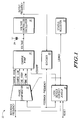
- FIG. 1 illustrates one embodiment of the present invention.
- the present invention implements a phase lock loop circuit 10.
- Phase lock loop circuit 10 generally includes a phase comparator 12, a charge pump 14, a capacitor 24, a voltage controlled oscillator 16, a lock detect circuit 18, a divider 20, and a status register 22.
- a Reference Frequency signal is provided to a first input of each of phase comparator 12 and lock detect circuit 18.
- a Reset signal is provided to a second input of lock detect circuit 18.
- a first output of lock detect circuit 18 is a signal labeled "Kickoff”.
- the Kickoff signal is provided to a first input of charge pump 14.
- a second output of lock detect circuit 18 is a signal labeled "Locked”.
- the Locked signal is provided to a second input of phase comparator and an input of status register 22.
- Phase comparator 12 has a plurality of outputs.
- a first output of phase comparator 12 is labeled "Coarse High” and is provided to a second input of charge pump 14.
- a second output of phase comparator 12 is labeled “Coarse Low” and is provided to a third input of charge pump 14.
- a third output of phase comparator 12 is labeled “Fine High” and is provided to a fourth input of charge pump 14.
- a fourth output of phase comparator 12 is labeled “Fine Low” and is provided to a fifth input of charge pump 14.
- Charge pump 14 has an output for providing a Voltage signal.
- the output of charge pump 14 is connected to a first terminal of capacitor 24 and an input of voltage controlled oscillator 16.
- a second terminal of capacitor 24 is connected to a power source (not shown).
- An output of voltage controlled oscillator 16 is labeled "Output Frequency" and is provided to both an external integrated circuits pin (not shown) and an input of divider 20.
- An output of divider 20 is connected to a second input of phase comparator 12 and a third input of lock detect circuit 18 to provide a signal labeled "Feedback Frequency".
- Lock detect circuit 18 is illustrated in more detail in FIG. 2.
- Lock detect circuit 18 generally includes a reference latch 26, a synchronizer 28, a feedback latch 30, a reference counter 32, a counter control circuit 34, a feedback counter 36, an anti-aliasing circuit 38, a feedback count detector 40, a first inverter 42, a second inverter 44, an auxiliary control generator 46, and a match detector 48.
- the Reference Frequency signal is provided to reference latch 26 via a data (D) input.
- the Reference Frequency signal is also provided to a first input of synchronizer 28.
- An output (Q) of reference latch 26 is connected to a first input of reference counter 32 to provide a signal labeled "Gated Reference Frequency”.
- the Reset signal is connected to a first input of each of reference counter 32, counter control circuit 34, and feedback counter 36.
- An output of reference counter 32 is connected to an input of counter control circuit 34 to provide a signal labeled "Freeze”.
- a first output of counter control circuit 34 is connected to an enable (EN) input of reference latch 26 and a second input of synchronizer 28 to provide a signal labeled "Reference Count Enable”.
- a second output of counter control circuit 34 is connected to anti-aliasing circuit 38 to provide a signal labeled "Toggle".
- An output of anti-aliasing circuit 38 is connected to a CMP29 input of feedback count detector to provide a signal labeled "CMP29".
- the output of anti-aliasing circuit 38 is also connected to an input of inverter 44.
- An output of inverter 44 is connected to a CMP25 input of feedback count detector 40.
- the Feedback Frequency signal is connected to a data (D) input of feedback latch 30.
- the Feedback Frequency signal is also connected to a third input of synchronizer 28.
- An output of synchronizer 28 is connected to an enable (EN) input of feedback latch 30 to provide a Feedback Count Enable signal.
- An output (Q) of feedback latch 30 is connected to a second input of feedback counter 36.
- Feedback counter 36 provides a signal labeled "Feedback Count" to an input of feedback count detector 40.
- a first output of feedback count detector 40 is connected to auxiliary control generator 46 to provide a signal labeled "Kickoff Control”.
- a first output of auxiliary control generator 46 provides a signal labeled "Kickoff".
- a second output of feedback control detector 40 is connected to an input of match detector 48 to provide a signal labeled "Match".
- An output of match detector 48 is connected to both a Locked input of feedback count detector 40 and an input of inverter 42 to provide the Locked signal.
- An output of inverter 42 is connected to an Exact input of feedback count detector 40.
- Feedback count detector 40 is illustrated in more detail in FIG. 3.
- Feedback count detector 40 generally includes a comparator 50, a comparator 52, a comparator 54, a comparator 56, an AND gate 58, an AND gate 60, an AND gate 62, an AND gate 64, an OR gate 66, and a comparator 70.
- the Feedback Count signal is provided to an input of each of comparator 50, comparator 52, comparator 54, comparator 56, and comparator 70.
- An output of comparator 50 is connected to a first input of AND gate 58 to provide a signal labeled "CNT25”.
- An output of comparator 52 is connected to a first input of AND gate 60 to provide a signal labeled "CNT25X”.
- An output of comparator 54 is connected to a first input of AND gate 62 to provide a signal labeled "CNT29”.
- An output of comparator 56 is connected to a first input of AND gate 64 to provide a signal labeled "CNT29X”.
- An output of comparator 70 provides the Kickoff Control signal.
- the Exact signal is connected to a second input of each of AND gate 58 and AND gate 62.
- the Locked signal is provided to a second input of each of AND gate 60 and AND gate 64.
- the CMP25 signal is connected to a third input of each of AND gate 58 and AND gate 60.
- the CMP29 signal is connected to a third input of each of AND gate 62 and AND gate 64.
- An output of AND gate 58 is connected to a first input of OR gate 66 and an output of AND gate 60 is connected to a second input of OR gate 66.
- An output of AND gate 62 is connected to a third input of OR gate 66 and an output of AND gate 64 is connected to a fourth input of OR gate 66.
- An output of OR gate 66 provides the Match signal.
- FIG. 4 illustrates one embodiment of anti-aliasing circuit 38.
- anti-aliasing circuit 38 is implemented as a flip-flop 68.
- the Toggle signal is provided to a clock (CLK) input of flip-flop 68.
- An output (Q) of flip-flop 68 is the CMP25 signal.
- An inverted output ( Q ⁇ ) of flip-flop 68 is connected to a data (D) input of flip-flop 68.
- the circuitry used to implement a flip-flop is well known in the data processing art and will not be discussed in more detail.
- the Reference Frequency signal is provided to the phase comparator 12 by an external source such as a crystal oscillator.
- Phase comparator 12 asserts one of the plurality of signals, Coarse High, Coarse Low, Fine High, and Fine Low, to indicate a relationship of the Feedback Frequency signal to the Reference Frequency signal.
- phase comparator 12 asserts the Coarse High signal to indicate that a coarse adjustment needs to be made to the Voltage signal.
- the Voltage signal is then provided to voltage controlled oscillator 16 such that the frequency of the Feedback Frequency signal is significantly increased.
- the Coarse Low signal is asserted to indicate that the frequency of the Feedback Frequency signal is significantly higher than the frequency of the Reference Frequency signal.
- the Coarse Low signal is asserted, the Voltage signal is appropriately modified and provided to voltage controlled oscillator 16 such that the frequency of the Feedback Frequency signal is significantly decreased.
- phase comparator 12 asserts one of the Fine High and Fine Low signals.
- the Fine High and Fine Low signals provide fine adjustment information to charge pump 14.
- Charge pump 14 reflects the fine adjustment information in the Voltage signal such that voltage controlled oscillator 16 adjust the frequency of the Feedback Frequency signal to either a slightly higher or a slightly lower frequency, respectively.
- Lock detect circuit 18 provides a negated Kickoff signal to charge pump 14.
- the Kickoff signal is used to enable charge pump 14 to quickly provide a voltage signal when the phase lock loop circuit is first powered on.
- voltage controlled oscillator 16 provides the output frequency in a predetermined range of frequencies, the Kickoff signal is asserted.
- charge pump 14 outputs the Voltage signal at a voltage level determined by one of the Coarse High, Coarse Low, Fine High, Fine Low, and Kickoff signals.
- Voltage controlled oscillator 16 receives the Voltage signal and provides the Output Frequency signal at a frequency which is proportional to the voltage level of the Voltage signal.
- the Output Frequency signal is provided to divider 20 where a frequency division operation is performed.
- the Feedback Frequency signal is the output of divider 20.
- a value by which the divider divides the Output Frequency signal is programmable by a user of phase lock loop circuit 10. Frequency dividers are well known in the data processing art and, as such, will not be discussed in further detail herein.
- the Feedback Frequency signal is subsequently provided to both phase comparator 12 to perform the operation described above and to lock detect circuit 18.
- the Feedback Frequency signal is tested to determine if phase lock loop circuit 10 has satisfied a frequency lock condition.
- a locked bit in status register 22 is asserted.
- a user of phase lock loop circuit 10 may then use that bit in status register 22 to determine if a stable clock is available for use in other data processing functions.
- lock detect circuit 18 determines whether or not the Reference Frequency signal and the Feedback Frequency signal are frequency locked by using reference counter 32 and feedback counter 36.
- Reference counter 32 is clocked by the Reference Frequency signal and feedback counter 36 is clocked by the Feedback Frequency signal.
- At the end of a first predetermined period of time an output of each of reference counter 32 and feedback counter 36 are compared.
- the outputs of each of reference counter 32 and feedback counter 36 are also compared at the end of a second predetermined period of time.
- the two count values must be equal at the end of both the first and the second periods of time. Additionally, by choosing the two periods of time such that they are not harmonically related to one another, a lock signal will not be erroneously detected even when the Feedback Frequency signal is aliasing.
- the potential for metastable operation is greatly decreased by providing a count window which is generated from the Reference Frequency signal and synchronized to the Feedback Frequency signal.
- the count window defines a range of frequencies for which the Feedback Frequency is considered to be locked to the Reference Frequency signal.
- the count window allows the Feedback Frequency signal to be within approximately 1.6% to 3.3% of the frequency of the Reference Frequency signal to still satisfy the locked condition.
- the lock detect circuit may indicate that phase lock loop circuit 10 is toggling in and out of lock. Frequency hysteresis is used to stabilize this characteristic.
- Frequency hysteresis opens up the count window such that the Feedback Frequency signal may be within an approximate lock range of -3.3% to +3.3% of the frequency of the Reference Frequency signal and still satisfy the lock condition.
- lock detect circuit 18 will negate the Locked signal and phase lock loop circuit 10 will be considered to be "unlocked”.
- the percentages of the lock range are determined by a bit width of the counters used to implement reference counter 32 and feedback counter 36.
- reference counter 32 and feedback counter 36 are both five bits wide.
- a precision of lock detect circuit 18 doubles for every counter stage which is added. For example, if reference counter 32 and feedback counter 36 had a bit width of six, the precision of lock detect circuit 18 would be in a range of +/-1.65%.
- the precision of lock detect circuit 18 increases. However, more stages also require more time to detect when a lock condition has been satisfied. Therefore, a user of phase lock loop circuit 10 must balance the precision of lock detect circuit 18 with a time required to detect when the lock condition has been satisfied.
- phase lock loop circuit 10 An overview of operation of phase lock loop circuit 10 has been provided hereto. Subsequently, operation of phase lock loop circuit 10 and lock detect circuit 18 will be described in more detail.
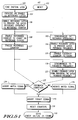
- FIG. 5-1 illustrates a first portion of a flow chart of operation of phase lock loop circuit 10. Operation of phase lock loop circuit 10 is generally initiated by a reset operation (Step 102) in a data processing system or an operation in which phase lock loop circuit 10 is initiated to provide the Output Frequency signal (Step 100). Upon initiation, counter control circuit 34 provides the Reference Count Enable signal to an enabled input of reference latch 26 (Step 104). Reference latch 26 is then enabled to receive and latch the Reference Frequency signal.
- the Gated Reference Frequency signal is provided to reference counter 32 (Step 106).
- Reference counter 32 counts for the first predetermined number of timing cycles of the Gated Reference Frequency signal (Step 108).
- the first predetermined number of timing cycles is equal to twenty-nine.
- reference counter 32 asserts the Freeze signal (Step 112). The Freeze signal is then provided to counter control circuit 34.
- synchronizer 28 While reference counter 32 is counting, synchronizer 28 is also enabled to synchronize the Feedback Frequency signal (Step 110). Synchronizer 28 provides the Feedback Count Enable signal to feedback latch 30 to synchronize feedback latch 30 to reference latch 26 such that the Gated Feedback Frequency signal is provided in synchrony with the Gated Reference Frequency signal (Step 114). The Feedback Count Enable signal enables feedback latch 30 to provide the Gated Feedback Frequency signal to feedback counter 36. Upon receipt of the Gated Feedback Frequency signal, feedback counter 36 begins to count (Step 116).
- the circuitry used to implement synchronizer 28 is well known in the data processing art and will not, therefore, be explained in further detail.
- synchronizer 28 is again enabled to synchronize the Reference Frequency signal to the Feedback Frequency signal (Step 118).
- the counter control circuit 34 negates the Reference Count Enable signal such that feedback latch 30 is not enabled to provided the Gated Feedback Frequency signal (Step 120). Therefore, feedback counter 36 no longer counts the timing cycles of the Gated Feedback Frequency signal.
- Feedback counter 36 counts for a same period of time as is required for reference counter 32 to count to twenty-nine and to assert the Freeze signal.
- the Feedback Count signal provides a count value to feedback count detector 40.
- Feedback count detector 40 determines whether or not the count value is equal to twenty-nine, the first predetermined number used to partially determine if a lock condition is satisfied and the Locked signal should be asserted by lock detect circuit 18 (Step 122). If the count value provided by the Feedback Count signal equals twenty-nine, the CNT29 signal is asserted.
- the Feedback Count signal is provided to each of comparators 50 through 56.
- comparator 54 is used to determine when the count value provided by the Feedback Count signal is equal to twenty-nine. When the count value provided by the Feedback Count signal is equal to twenty-nine, comparator 54 asserts the CNT29 signal.
- the asserted CNT29 signal is provided to AND gate 62.
- the CMP29 signal is asserted by anti-aliasing circuit 38 and is provided to AND gate 62. When asserted, the CMP29 signal indicates that reference counter 32 has counted to twenty-nine.
- a third input to AND gate 62, the Exact signal is also asserted.
- the Exact signal is an inversion of the Locked signal and is asserted when the locked condition is not satisfied by phase lock loop circuit 10. Because each of its inputs is asserted, AND gate 62 provides an asserted output to OR gate 66. OR gate 66 subsequently asserts the Match signal (Step 124).
- the CNT29 signal is not asserted and, therefore, the Match signal is not asserted (Step 126).
- the Toggle signal is subsequently asserted to indicate that reference counter 32 has reached a count of twenty-nine and has asserted the Freeze signal (Step 125).
- Anti-aliasing circuit 38 uses the Toggle signal to determine a number of timing cycles which reference counter 32 should be counting before asserting the Freeze signal.
- the count value provided feedback counter 36 must be equal to the count value of reference counter 32 for two consecutive periods of time. The two periods of time are chosen such that they are not harmonically related to one another. Therefore, a lock signal is not erroneously detected when the Feedback Frequency signal is aliasing.
- FIG. 4 illustrates anti-aliasing circuit 38 in more detail.
- the Toggle signal provides the clock input to flip-flop 68 which is used to implement anti-aliasing circuit in the embodiment of the invention described herein.
- the data input of flip-flop 68 is provided by an inverted data output of flip-flop 68.
- the CMP29 signal output by the data output of flip-flop 68 is negated and the inverted data output of flip-flop 68 is asserted. Therefore, when the Toggle signal is asserted, the CMP29 signal is asserted and provided to feedback count detector 40 and inverter 44. Subsequently, the CMP29 input is asserted and the CMP25 input is negated.
- the inverted data output of flip-flop 68 is negated. Therefore, when the Toggle signal is asserted next to indicate that reference counter 32 has counted to twenty-five, the CMP29 signal is negated and provided to inverter 44 and to the CMP29 input of feedback count detector 40. The CMP29 input is then negated and the CMP25 input is asserted.
- both reference counter 32 and feedback counter 36 are reset to an initialized state (Step 128).
- a next set of steps is performed to determine whether or not the lock condition has been satisfied by phase lock loop circuit 10 (Step 130).
- Step 131 initiates the next set of steps to determine if the lock condition has been achieved in phase lock loop 10.
- Counter control circuit 34 again provides the Reference Count Enable signal to an enabled input of reference latch 26 (Step 132).
- Reference latch 26 is then enabled to receive and latch the Reference Frequency signal.
- the Gated Reference Frequency signal is provided to reference counter 32 (Step 133).
- the Gated Reference Frequency signal is provided to reference counter 32 and reference counter 32 counts for the second predetermined number of timing cycles of the Gated Reference Frequency signal (Step 134).
- the second predetermined number of timing cycles is equal to twenty-five.
- reference counter 32 asserts the Freeze signal (Step 138). The Freeze signal is then provided to counter control circuit 34.
- synchronizer 28 While reference counter 32 is counting, synchronizer 28 is also enabled to synchronize the Feedback Frequency signal (Step 136). Synchronizer 28 provides the Feedback Count Enable signal to feedback latch 30 to synchronize feedback latch 30 to reference latch 26 such that the Gated Feedback Frequency signal is provided in synchrony with the Gated Reference Frequency signal (Step 140). The Feedback Count Enable signal enables feedback latch 30 to provide the Gated Feedback Frequency signal to feedback counter 36. Upon receipt of the Gated Feedback Frequency signal, feedback counter 36 begins to count (Step 141).
- synchronizer 28 is enabled to synchronize the Reference Frequency signal to the Feedback Frequency signal (Step 142).
- the counter control circuit 34 negates the Reference Count Enable signal such that feedback latch 30 is not enabled to provide the Gated Feedback Frequency signal (Step 144).
- feedback counter 36 no longer counts the timing cycles of the Gated Feedback Frequency signal. Therefore, feedback counter 36 counts for a same period of time as is required for reference counter 32 to count to twenty-five and to assert the Freeze signal.
- the Feedback Count signal provides a count value to feedback count detector 40.
- Feedback count detector 40 determines whether or not the count value is equal to twenty-five, the second predetermined number used to determine if a lock condition is satisfied and the Locked signal should be asserted by lock detect circuit 18 (Step 146). If the count value provided by the Feedback Count signal equals twenty-five, the CNT25 signal is asserted (Step 148).
- comparator 50 is used to determine when the count value provided by the Feedback Count signal is equal to twenty-five. When the count value provided by the Feedback Count signal is equal to twenty-five, comparator 50 asserts the CNT25 signal. The asserted CNT25 signal is provided to AND gate 58. Additionally, the CMP25 signal is asserted and is provided to AND gate 58. A third input to AND gate 58, the Exact signal, is also asserted. As was previously described, the Exact signal is the inversion of the Locked signal and is asserted when the locked condition is not satisfied by phase lock loop circuit 10. Because each of its inputs is asserted, AND gate 58 provides an asserted output to OR gate 66. OR gate 66 subsequently asserts the Match signal (Step 148).
- the Match signal when the CNT25 signal is asserted, the Match signal is also asserted. However, when the count value is not equal to twenty-five, the Match signal is negated (Step 150).
- counter control circuit 34 pulses the Toggle signal to indicate that reference counter 32 has reached a count of twenty-five and has asserted the Freeze signal (Step 151).
- anti-aliasing circuit 38 negates the CMP29 signal to indicate that reference counter 32 has counted to twenty-five.
- the CMP29 signal is negated and provided to inverter 44 and to the CMP29 input of feedback count detector 40. The CMP29 input is then negated and the CMP25 input is asserted.
- match detector 48 detects the asserted Match signal. As was previously mentioned, match detector 48 requires that the Match signal be asserted for two consecutive periods of time. In the embodiment of the invention described herein, the count value provided by the Feedback Count signal must be equal to the count value of reference counter 32.
- the count value of reference counter 32 is equal to twenty-nine for the first period of time and to twenty-five for the second period of time.
- Match detector 48 determines whether or not this condition has been met before asserting the Locked signal to indicate that phase lock loop circuit 10 has met the lock criteria (Step 152). Match detector 48 determines whether or not the Match signal was asserted to indicate that the count value provided by the Feedback Count signal was equal to twenty-nine during a first period of time and was equal to twenty-five during a second consecutive period of time.
- match detector 48 asserts the Locked signal to indicate that phase lock loop circuit 10 has achieved the lock condition (Step 154).
- the Locked signal is provided to status register 22 to set the locked bit stored therein (Step 155).
- each of counters 32 and 36 is reset to an initial value (Step 156) and phase lock loop 10 is monitored to indicate when phase lock loop circuit 10 is no longer in the locked state (Step 158).
- Match detector 48 does not assert the Locked signal.
- Both reference counter 32 and feedback counter 36 are subsequently reset to an initialized state (Step 160).
- a lock detect circuit 18 again begins to try to determine when an initial lock condition has been satisfied (Step 162). Lock detect circuit 18 performs the previously described set of steps until lock is achieved and the Locked signal is asserted.
- FIG. 5-3 illustrates a set of steps which are performed after the Locked signal is first asserted.
- phase lock loop 10 is monitored to indicate when phase lock loop circuit 10 is no longer in the locked state (Step 158).
- phase lock loop circuit 10 is considered to be in a locked state.
- lock detect circuit 18 may indicate that phase lock loop circuit 10 is toggling in and out of lock.
- Frequency hysteresis is used to stabilize this characteristic by opening up the count window such that the Feedback Frequency signal may be within an approximate lock range of -3.3% to +3.3% of the frequency of the Reference Frequency signal and still satisfy the lock condition.
- lock detect circuit 18 will negate the Locked signal and phase lock loop circuit 10 will be considered to be "unlocked”.
- feedback count detector 40 does not require the count value provided by the Feedback Count signal to be equal to the count value of reference counter 32 after lock detect circuit 18 initially determines that the lock condition has been achieved. Once the lock condition has been achieved and the Locked signal is initially asserted, lock detect circuit 18 allows the count value provided by the Feedback Count signal to be within +/-1 of the count value of reference counter 32. By allowing a broader range of frequencies, lock detect circuit 18 will not erroneously detect that phase lock loop circuit 10 is in lock or out of lock when the frequency of the Feedback Frequency signal oscillates slightly around the frequency of the Reference Frequency signal.
- FIG. 5-3 illustrates a third portion of the flow chart of operation of phase lock loop circuit 10 in which the lock of phase lock loop circuit 10 is monitored after the Locked signal is initially asserted.
- counter control circuit 34 provides the Reference Count Enable signal to an enabled input of reference latch 26 (Step 163).
- Reference latch 26 is then enabled to receive and latch the Reference Frequency signal.
- the Gated Reference Frequency signal is provided to reference counter 32 (Step 164).
- the Gated Reference Frequency signal is provided to reference counter 32.
- Reference counter 32 counts for twenty-nine timing cycles of the Gated Reference Frequency signal (Step 166). When twenty-nine timing cycles of the Gated Reference Frequency signal have been counter, reference counter 32 asserts the Freeze signal (Step 168). The Freeze signal is then provided to counter control circuit 34.
- synchronizer 28 While reference counter 32 is counting, synchronizer 28 is also enabled to synchronize the Feedback Frequency signal (Step 170). Synchronizer 28 provides the Feedback Count Enable signal to feedback latch 30 to synchronize feedback latch 30 to reference latch 26 such that the Gated Feedback Frequency signal is provided in synchrony with the Gated Reference Frequency signal (Step 172). The Feedback Count Enable signal enables feedback latch 30 to provide the Gated Feedback Frequency signal to feedback counter 36. Upon receipt of the Gated Feedback Frequency signal, feedback counter 36 begins to count (Step 173).
- synchronizer 28 is enabled to synchronize the Reference Frequency signal to the Feedback Frequency signal (Step 174).
- the counter control circuit 34 negates the Reference Count Enable signal such that feedback latch 30 is not enabled to provided the Gated Feedback Frequency signal (Step 176).
- feedback counter 36 no longer counts the timing cycles of the Gated Feedback Frequency signal. Therefore, feedback counter 36 counts for a same period of time as is required for reference counter 32 to count to twenty-nine and to assert the Freeze signal.
- the Feedback Count signal provides the count value to feedback count detector 40.
- Feedback count detector 40 determines whether or not the count value is equal to either twenty-eight, twenty-nine, or thirty. Theses numbers were chosen to be equal to 29 ⁇ 1 such that frequency hysteresis will not result in lock detect circuit erroneously indicating that phase lock loop circuit 10 is not in a locked state (Step 178).
- twenty-nine is the first predetermined number used to partially determine if a lock condition is satisfied and the Locked signal should be asserted by lock detect circuit 18. If the count value provided by the Feedback Count signal equals either twenty-eight, twenty-nine, or thirty, the CNT29X signal is generated.
- the Feedback Count signal is provided to each of comparators 50 through 56.
- comparator 56 is used to determine when the count value provided by the Feedback Count signal is equal to either twenty-eight, twenty-nine, or thirty.
- comparator 56 asserts the CNT29X signal.
- the asserted CNT29X signal is provided to AND gate 64.
- the CMP29 signal is asserted and is provided to AND gate 64 to indicate that reference counter 32 is counting to twenty-nine, rather than twenty-five.
- a third input to AND gate 64, the Locked signal, is also asserted.
- the Locked signal is asserted because phase lock loop circuit 10 is in the locked state. Because each of its inputs is asserted, AND gate 64 provides an asserted output to OR gate 66. OR gate 66 subsequently allows the Match signal to remain asserted (Step 179).
- counter control circuit 34 asserts the Toggle signal to indicate that reference counter 32 has reached a count of twenty-nine and has asserted the Freeze signal (Step 180).
- Each of counters 32 and 36 are then reset to an initialized state (Step 181) and lock detect circuit 10 continues to monitor the locked state of phase locked loop circuit 10 (Step 182).
- the CNT29X signal When the count value is not equal to either twenty-eight, twenty-nine, or thirty, the CNT29X signal is not asserted and, therefore, the Match signal is negated (Step 183).
- match detector 48 When the Match signal is negated, match detector 48 negates the Locked signal to indicate that phase lock loop circuit 10 is no longer in the locked state. Subsequently, the Locked signal is provided to status register 22 to negate a Locked flag stored therein (Step 184).
- Both reference counter 32 and feedback counter 36 are then reset to an initialized state (Step 186).
- lock detect circuit 18 again begins to try to determine when an initial lock condition has been satisfied (Step 162).
- Lock detect circuit 18 performs the set of steps illustrated in FIG. 5-1 and FIG. 5-2 until lock is achieved and the Locked signal is asserted.
- FIG. 5-4 illustrates a next portion of the flow chart of operation in which the lock of phase lock loop circuit 10 continues to be monitored after the Locked signal is initially asserted.
- counter control circuit 34 provides the Reference Count Enable signal to an enabled input of reference latch 26 (Step 187).
- Reference latch 26 is then enabled to receive and latch the Reference Frequency signal.
- the Gated Reference Frequency signal is provided to reference counter 32 (Step 188).
- the Gated Reference Frequency signal is provided to reference counter 32.
- Reference counter 32 counts for twenty-five timing cycles of the Gated Reference Frequency signal (Step 190).
- reference counter 32 asserts the Freeze signal (Step 192).
- the Freeze signal is then provided to counter control circuit 34.
- synchronizer 28 While reference counter 32 is counting, synchronizer 28 is also enabled to synchronize the Feedback Frequency signal (Step 194). Synchronizer 28 provides the Feedback Count Enable signal to feedback latch 30 to synchronize feedback latch 30 to reference latch 26 such that the Gated Feedback Frequency signal is provided in synchrony with the Gated Reference Frequency signal (Step 196). The Feedback Count Enable signal enables feedback latch 30 to provide the Gated Feedback Frequency signal to feedback counter 36. Upon receipt of the Gated Feedback Frequency signal, feedback counter 36 begins to count (Step 197).
- synchronizer 28 is enabled to synchronize the Reference Frequency signal to the Feedback Frequency signal (Step 198).
- the counter control circuit 34 negates the Reference Count Enable signal such that feedback latch 30 is not enabled to provided the Gated Feedback Frequency signal (Step 200).
- feedback counter 36 no longer count the timing cycles of the Gated Feedback Frequency signal. Therefore, feedback counter 36 counts for a same period of time as is required for reference counter 32 to count to twenty-five and to assert the Freeze signal.
- the Feedback Count signal provides the count value to feedback count detector 40.
- Feedback count detector 40 determines whether or not the count value is equal to either twenty-four, twenty-five, or twenty-six. Theses numbers were chosen to be equal to 25 ⁇ 1 such that frequency hysteresis will not result in lock detect circuit erroneously indicating that phase lock loop circuit 10 is not in a locked state (Step 202).
- twenty-five is the second number used to partially determine if a lock condition is satisfied and the Locked signal should be asserted by lock detect circuit 18. If the count value provided by the Feedback Count signal equals either twenty-four, twenty-five, or twenty-six, the CNT25X signal is generated.
- comparator 52 is used to determine when the count value provided by the Feedback Count signal is equal to either twenty-four, twenty-five, or twenty-six. When the count value provided by the Feedback Count signal is equal to one of the values listed above, comparator 52 asserts the CNT25X signal. The asserted CNT25X signal is provided to AND gate 60. Additionally, the CMP25 signal is asserted and is provided to AND gate 60 to indicate that reference counter 32 is counting to twenty-five, rather than twenty-nine. A third input to AND gate 64, the Locked signal, is also asserted. The Locked signal is asserted because phase lock loop circuit 10 is in the locked state. Because each of its inputs is asserted, AND gate 60 provides an asserted output to OR gate 66. OR gate 66 subsequently allows the Match signal to remain asserted (Step 201).
- counter control circuit 34 asserts the Toggle signal to indicate that reference counter 32 has reached a count of twenty-five and has asserted the Freeze signal (Step 203).
- Each of counters 32 and 36 are then reset to an initialized state (Step 204) and lock detect circuit 10 continues to monitor the locked state of phase locked loop circuit 10 (Step 158).
- the CNT25X signal When the count value is not equal to either twenty-four, twenty-five, or twenty-six, the CNT25X signal is not asserted and, therefore, the Match signal is negated (Step 205). As well, counter control circuit 34 pulses the Toggle signal to indicate that reference counter 32 has reached a count of twenty-five and has asserted the Freeze signal (Step 207). When the Match signal is negated, match detector 48 negates the Locked signal to indicate that phase lock loop circuit 10 is no longer in the locked state. Subsequently, the Locked signal is provided to status register 22 to negate a Locked flag stored therein (Step 206).
- Both reference counter 32 and feedback counter 36 are then reset to an initialized state (Step 208).
- lock detect circuit 18 again begins to try to determine when an initial lock condition has been satisfied (Step 162).
- Lock detect circuit 18 performs the set of steps illustrated in FIG. 5-1 and FIG. 5-2 until lock is achieved and the Locked signal is asserted.
- lock detect circuit 18 In addition to detecting when phase lock loop circuit 10 is in the locked state, lock detect circuit 18 also uses a relationship between the Reference Frequency signal and the Feedback Frequency signal to control operating parameters of phase lock loop circuit 10. For example, feedback count detector 40 is used to determine when charge pump 14 should be quickly ramped on to quickly increase the voltage of the Voltage signal and when charge pump 14 should be used more moderately to modify the voltage of the Voltage signal at a slower pace. Such operations are used to enable phase lock loop circuit 10 to satisfy the lock condition more quickly when phase lock loop circuit 10 is first powered up.
- phase lock loop circuit 10 When phase lock loop circuit 10 is first powered up, feedback count detector 40 negates the Kickoff Control signal.
- the Kickoff Control signal remains negated until the count value provided by the Feedback Count signal is equal to a kickoff count value which is determined by a user of phase lock loop circuit 10.
- the kickoff count value is equal to sixteen such that charge pump 14 quickly increases the Voltage signal until the resulting Feedback Frequency is within approximately fifty percent of the frequency of the Reference Frequency signal.
- comparator 70 asserts the Kickoff Control signal.
- the Kickoff Control signal is provided to auxiliary control generator 46 to produce the Kickoff signal.
- the Kickoff signal is provided to charge pump 14 to decrease the rate at which charge pump 14 is increasing the voltage of the Voltage signal. Subsequently, the rate at which the frequency of the Feedback Frequency signal is changing is also decreased.
- lock detect circuit 18 is able to control operation of charge pump 14 such that phase lock loop 10 achieves the lock condition more efficiently.
- the frequency of the Feedback Frequency signal may be controlled such that it does not "overshoot" the frequency of the Reference Frequency signal. Therefore, fewer iterations of raising and lowering the frequency of the Feedback Frequency signal are required for phase lock loop circuit 10 to achieve the locked state.
- Lock detect circuit 18 provides a unique circuit and method for detecting lock in a phase locked loop system. Two counters are used to count the timing cycles of a reference frequency and a feedback frequency over two periods of time to determine if the phase locked loop system is in the locked state. The two counters must be equal for both periods of time before lock detect circuit 18 will indicate that phase lock loop circuit 18 has satisfied the lock condition. Because the two periods of time used during this measurement are not harmonically related, aliasing between the feedback frequency and the reference frequency will be detected and lock detect circuit 18 will not indicate that the phase locked loop system is in the lock condition. In some cases, aliasing of the feedback frequency may result in an erroneous lock detection if only one period of time were used. However, by using two periods of time which are not harmonically related, the lock condition will only be detected when the feedback frequency is actually locked to the reference frequency.
- lock detect circuit 18 widens a lock range used to detect lock so that frequency hysteresis will not result in the detection of an unlocked condition.
- the feedback frequency must then drift completely outside the lock range for the phase locked loop system to be unlocked.
- Lock detect circuit 18 performs each of these functions using only digital logic. No analog devices are used. In prior art devices, an analog integrator was required to detect the locked condition. The integrator typically required near-exact phase match as well as precise values of analog components to detect the locked condition. Such precise values are typically difficult to obtain on an integrated circuit. However, the digital logic used to implement lock detect circuit 18 is easily reproduced and is not sensitive to minor variations in the processing parameters used to form the integrated circuits. Therefore, the accuracy of lock detect circuit 18 may be more closely controlled and more reliable results will be generated. Additionally, analog circuitry is typically susceptible to noise in a digital system which may decrease the reliability of the phase lock loop system. Because lock detect circuit 18 has no analog circuitry, lock detect circuit 18 is less likely than traditional analog circuitry to erroneously indicate that the phase locked loop system is either locked or unlocked.
- lock detect circuit 18 uses frequency based match detection to detect lock in the phase locked loop system.
- Prior art systems have generally used phase matching to detect lock.
- Phase matching is very sensitive to phase jitter which is inherent in most voltage controlled oscillators. Because lock detect circuit 18 uses frequency matching, the phase jitter inherent in voltage controlled oscillators is inconsequential.
- lock detect circuit 18 provides a more efficient circuit for determining lock in the phase locked loop system.
- each of counters 32 and 36 may have a bit width which is greater than or less than five.
- a bit width of five was chosen in this embodiment of the invention because it provides an appropriate balance between accuracy and rate of lock detection. More bit width provides greater accuracy during a lock detection operation and less bit width provide a faster rate of lock detection.
- an order in which the count values are performed may be changed.
- the order of the count values provided herein is provided for example only.
- the lock detect circuit disclosed herein may detect a count of twenty-five before detecting a count of twenty-nine. Additionally, the count values may be any two numbers which are not harmonically related. The count values should not be restricted to the values disclosed herein.
Applications Claiming Priority (2)
| Application Number | Priority Date | Filing Date | Title |
|---|---|---|---|
| US88951 | 1993-07-12 | ||
| US08/088,951 US5394444A (en) | 1993-07-12 | 1993-07-12 | Lock detect circuit for detecting a lock condition in a phase locked loop and method therefor |
Publications (1)
| Publication Number | Publication Date |
|---|---|
| EP0637138A1 true EP0637138A1 (fr) | 1995-02-01 |
Family
ID=22214466
Family Applications (1)
| Application Number | Title | Priority Date | Filing Date |
|---|---|---|---|
| EP94109894A Ceased EP0637138A1 (fr) | 1993-07-12 | 1994-06-27 | Circuit de détection de synchronisation |
Country Status (3)
| Country | Link |
|---|---|
| US (1) | US5394444A (fr) |
| EP (1) | EP0637138A1 (fr) |
| JP (1) | JP3886167B2 (fr) |
Cited By (5)
| Publication number | Priority date | Publication date | Assignee | Title |
|---|---|---|---|---|
| EP0821488A1 (fr) * | 1996-07-24 | 1998-01-28 | Koninklijke Philips Electronics N.V. | Dispositif de sélection de fréquence muni d'un détecteur de verrouillage |
| EP0783204A3 (fr) * | 1996-01-05 | 1998-06-17 | International Business Machines Corporation | Circuit indicateur de verrouillage en fréquence |
| EP0878912A2 (fr) * | 1997-05-15 | 1998-11-18 | Siemens Aktiengesellschaft | Circuit de détection de verrouillage pour une boucle à verrouillage de phase |
| US7317359B2 (en) | 2006-02-08 | 2008-01-08 | Seiko Epson Corporation | Circuits and methods for phase locked loop lock window detection |
| US7782143B2 (en) | 2007-03-08 | 2010-08-24 | Integrated Device Technology, Inc. | Phase locked loop and delay locked loop with chopper stabilized phase offset |
Families Citing this family (33)
| Publication number | Priority date | Publication date | Assignee | Title |
|---|---|---|---|---|
| US5764712A (en) * | 1996-04-18 | 1998-06-09 | International Business Machines Corporation | Phase locked loop circuit having automatic range setting logic |
| US6774685B2 (en) * | 1996-05-13 | 2004-08-10 | Micron Technology, Inc. | Radio frequency data communications device |
| US6696879B1 (en) | 1996-05-13 | 2004-02-24 | Micron Technology, Inc. | Radio frequency data communications device |
| US6836468B1 (en) | 1996-05-13 | 2004-12-28 | Micron Technology, Inc. | Radio frequency data communications device |
| US6941124B1 (en) | 1996-05-13 | 2005-09-06 | Micron Technology, Inc. | Method of speeding power-up of an amplifier, and amplifier |
| US6130602A (en) | 1996-05-13 | 2000-10-10 | Micron Technology, Inc. | Radio frequency data communications device |
| US5870002A (en) * | 1997-06-23 | 1999-02-09 | Exar Corporation | Phase-frequency lock detector |
| US6215834B1 (en) | 1997-08-04 | 2001-04-10 | Motorola Inc. | Dual bandwidth phase locked loop frequency lock detection system and method |
| US6069630A (en) * | 1997-08-22 | 2000-05-30 | International Business Machines Corporation | Data processing system and method for creating a link map |
| US5907253A (en) * | 1997-11-24 | 1999-05-25 | National Semiconductor Corporation | Fractional-N phase-lock loop with delay line loop having self-calibrating fractional delay element |
| US6005425A (en) * | 1998-02-04 | 1999-12-21 | Via-Cyrix Inc. | PLL using pulse width detection for frequency and phase error correction |
| KR100284780B1 (ko) * | 1998-04-20 | 2001-03-15 | 윤종용 | 위상 동기 루프 회로의 위상 락 검출 회로 |
| US6760394B1 (en) * | 1999-08-11 | 2004-07-06 | Broadcom Corporation | CMOS lock detect with double protection |
| DE60023833T2 (de) * | 1999-08-24 | 2006-07-20 | Koninklijke Philips Electronics N.V. | Phasenregelkreisschaltung mit einer ladungspumpe |
| US6265947B1 (en) * | 2000-01-11 | 2001-07-24 | Ericsson Inc. | Power conserving phase-locked loop and method |
| US6798858B1 (en) | 2000-02-04 | 2004-09-28 | International Business Machines Corporation | Lock detector for delay or phase locked loops |
| US6320469B1 (en) * | 2000-02-15 | 2001-11-20 | Agere Systems Guardian Corp. | Lock detector for phase-locked loop |
| DE10038880C2 (de) * | 2000-08-09 | 2002-06-20 | Siemens Ag | Phasendetektor für einen Phasenregelkreis |
| JP4502165B2 (ja) * | 2001-04-10 | 2010-07-14 | ルネサスエレクトロニクス株式会社 | ロック検出回路 |
| US7082178B2 (en) * | 2001-12-14 | 2006-07-25 | Seiko Epson Corporation | Lock detector circuit for dejitter phase lock loop (PLL) |
| US6670834B1 (en) * | 2002-09-12 | 2003-12-30 | Lsi Logic Corporation | Digital lock detect for dithering phase lock loops |
| US7023285B2 (en) * | 2003-07-15 | 2006-04-04 | Telefonaktiebolaget Lm Ericsson (Publ) | Self-calibrating controllable oscillator |
| US6879195B2 (en) * | 2003-07-17 | 2005-04-12 | Rambus, Inc. | PLL lock detection circuit using edge detection |
| US7157948B2 (en) * | 2004-09-10 | 2007-01-02 | Lsi Logic Corporation | Method and apparatus for calibrating a delay line |
| US7157978B2 (en) * | 2005-04-08 | 2007-01-02 | Via Telecom Co., Ltd. | Method and system for a lock detector for a phase-locked loop |
| US20070124897A1 (en) * | 2005-12-01 | 2007-06-07 | Wilson Eric J | Clamp for circular objects |
| US7711078B2 (en) * | 2007-06-01 | 2010-05-04 | Smsc Holdings Sarl | Frequency synchronization |
| US7649421B2 (en) * | 2007-06-19 | 2010-01-19 | Harris Stratex Networks Operating Corporation | Quality of phase lock and loss of lock detector |
| US9281828B2 (en) * | 2011-06-10 | 2016-03-08 | Broadcom Corporation | Reference-less voltage controlled oscillator (VCO) calibration |
| US8502609B2 (en) | 2011-06-10 | 2013-08-06 | Broadcom Corporation | Reference-less frequency detector |
| US8456206B2 (en) | 2011-06-20 | 2013-06-04 | Skyworks Solutions, Inc. | Phase-locked loop lock detect |
| US9252788B1 (en) | 2014-09-11 | 2016-02-02 | International Business Machines Corporation | Phase error detection in phase lock loop and delay lock loop devices |
| JP2019204998A (ja) * | 2018-05-21 | 2019-11-28 | 株式会社デンソー | Pll回路 |
Citations (4)
| Publication number | Priority date | Publication date | Assignee | Title |
|---|---|---|---|---|
| US4872155A (en) * | 1987-03-13 | 1989-10-03 | Pioneer Electronic Corporation | Clock generator circuit and a synchronizing signal detection method in a sampled format system and a phase comparator circuit suited for generation of the clock |
| US5128632A (en) * | 1991-05-16 | 1992-07-07 | Motorola, Inc. | Adaptive lock time controller for a frequency synthesizer and method therefor |
| US5220295A (en) * | 1992-04-13 | 1993-06-15 | Cirrus Logic, Inc. | Method and apparatus for detecting and correcting loss of frequency lock in a phase locked dual clock system |
| GB2271480A (en) * | 1992-09-25 | 1994-04-13 | Fujitsu Ltd | Frequency synthesisers |
Family Cites Families (12)
| Publication number | Priority date | Publication date | Assignee | Title |
|---|---|---|---|---|
| US3863156A (en) * | 1973-03-21 | 1975-01-28 | Itt | Frequency lock loop employing a gated frequency difference detector |
| US4639680A (en) * | 1985-04-12 | 1987-01-27 | Sperry Corporation | Digital phase and frequency detector |
| DE3537477A1 (de) * | 1985-10-22 | 1987-04-23 | Porsche Ag | Anordnung zur individuellen anpassung einer seriellen schnittstelle eines datenverarbeitenden systems an eine datenuebertragungsgeschwindigkeit eines kommunikationspartners |
| JPH01231430A (ja) * | 1988-03-10 | 1989-09-14 | Nec Corp | Pllロック検出回路 |
| US4876518A (en) * | 1988-12-02 | 1989-10-24 | Motorola Inc. | Frequency tracking system |
| CA2010265C (fr) * | 1989-02-17 | 1994-03-08 | Hiroshi Horie | Appareil a boucle a phase asservie |
| FI87026C (fi) * | 1989-12-01 | 1992-11-10 | Nokia Mobile Phones Ltd | Pao en digital faslaosningskrets baserad frekvensdetektor |
| US5008635A (en) * | 1990-06-25 | 1991-04-16 | Motorola, Inc. | Phase-lock-loop lock indicator circuit |
| US5278702A (en) * | 1991-04-12 | 1994-01-11 | Western Digital Corporation | Data synchronizer with symmetric window generation |
| US5260979A (en) * | 1991-05-28 | 1993-11-09 | Codex Corp. | Circuit and method of switching between redundant clocks for a phase lock loop |
| US5126690A (en) * | 1991-08-08 | 1992-06-30 | International Business Machines Corporation | Phase locked loop lock detector including loss of lock and gain of lock detectors |
| US5168245A (en) * | 1991-10-30 | 1992-12-01 | International Business Machines Corporation | Monolithic digital phaselock loop circuit having an expanded pull-in range |
-
1993
- 1993-07-12 US US08/088,951 patent/US5394444A/en not_active Expired - Lifetime
-
1994
- 1994-06-27 EP EP94109894A patent/EP0637138A1/fr not_active Ceased
- 1994-07-08 JP JP18082994A patent/JP3886167B2/ja not_active Expired - Lifetime
Patent Citations (4)
| Publication number | Priority date | Publication date | Assignee | Title |
|---|---|---|---|---|
| US4872155A (en) * | 1987-03-13 | 1989-10-03 | Pioneer Electronic Corporation | Clock generator circuit and a synchronizing signal detection method in a sampled format system and a phase comparator circuit suited for generation of the clock |
| US5128632A (en) * | 1991-05-16 | 1992-07-07 | Motorola, Inc. | Adaptive lock time controller for a frequency synthesizer and method therefor |
| US5220295A (en) * | 1992-04-13 | 1993-06-15 | Cirrus Logic, Inc. | Method and apparatus for detecting and correcting loss of frequency lock in a phase locked dual clock system |
| GB2271480A (en) * | 1992-09-25 | 1994-04-13 | Fujitsu Ltd | Frequency synthesisers |
Cited By (8)
| Publication number | Priority date | Publication date | Assignee | Title |
|---|---|---|---|---|
| EP0783204A3 (fr) * | 1996-01-05 | 1998-06-17 | International Business Machines Corporation | Circuit indicateur de verrouillage en fréquence |
| EP0821488A1 (fr) * | 1996-07-24 | 1998-01-28 | Koninklijke Philips Electronics N.V. | Dispositif de sélection de fréquence muni d'un détecteur de verrouillage |
| FR2751809A1 (fr) * | 1996-07-24 | 1998-01-30 | Philips Electronics Nv | Dispositif de selection de frequence muni d'un detecteur de verrouillage |
| EP0878912A2 (fr) * | 1997-05-15 | 1998-11-18 | Siemens Aktiengesellschaft | Circuit de détection de verrouillage pour une boucle à verrouillage de phase |
| EP0878912A3 (fr) * | 1997-05-15 | 1999-06-16 | Siemens Aktiengesellschaft | Circuit de détection de verrouillage pour une boucle à verrouillage de phase |
| US6314150B1 (en) | 1997-05-15 | 2001-11-06 | Infineon Technologies Ag | Lock detector circuit for a phase-locked loop |
| US7317359B2 (en) | 2006-02-08 | 2008-01-08 | Seiko Epson Corporation | Circuits and methods for phase locked loop lock window detection |
| US7782143B2 (en) | 2007-03-08 | 2010-08-24 | Integrated Device Technology, Inc. | Phase locked loop and delay locked loop with chopper stabilized phase offset |
Also Published As
| Publication number | Publication date |
|---|---|
| JP3886167B2 (ja) | 2007-02-28 |
| US5394444A (en) | 1995-02-28 |
| JPH0795061A (ja) | 1995-04-07 |
Similar Documents
| Publication | Publication Date | Title |
|---|---|---|
| US5394444A (en) | Lock detect circuit for detecting a lock condition in a phase locked loop and method therefor | |
| US6970046B2 (en) | Digital phase-locked loop | |
| US5530383A (en) | Method and apparatus for a frequency detection circuit for use in a phase locked loop | |
| JP3299636B2 (ja) | ジッタが補償される低電力の位相ロック・ループとその方法 | |
| US5483558A (en) | Method and apparatus for detecting phase or frequency lock | |
| EP1249936A2 (fr) | Circuit de détection de verrouillage | |
| US10819355B1 (en) | Phase to digital converter | |
| US5159279A (en) | Apparatus and method for detecting out-of-lock condition in a phase lock loop | |
| US7642862B2 (en) | Digital phase locked loop | |
| US7015727B2 (en) | Generating a lock signal indicating whether an output clock signal generated by a PLL is in lock with an input reference signal | |
| EP0600680B1 (fr) | Détecteur de verrouillage sur une fréquence harmonique | |
| EP0435552B1 (fr) | Circuit d'asservissement de phase à temps de blocage en fréquence/phase réduit | |
| US5506531A (en) | Phase locked loop circuit providing increase locking operation speed using an unlock detector | |
| US6229864B1 (en) | Phase locked loop lock condition detector | |
| JP3523362B2 (ja) | クロック回路及びこれを用いたプロセッサ | |
| US4801894A (en) | Frequency detector for frequency locked loop | |
| JP4296135B2 (ja) | Pllクロック出力安定化回路 | |
| US6990165B2 (en) | Phase and frequency lock detector | |
| CN113193868A (zh) | 锁相检测装置和锁相检测方法、锁相环 | |
| JP2531269B2 (ja) | 同期検出方式 | |
| JP3665512B2 (ja) | 二値信号の比較装置及びこれを用いたpll回路 | |
| US7157942B2 (en) | Digital frequency difference detector with inherent low pass filtering and lock detection | |
| CN215186702U (zh) | 锁相检测装置、锁相环 | |
| US6563386B1 (en) | Self-starter for PLL synthesizers | |
| KR0137494B1 (ko) | 위상차 검출회로 |
Legal Events
| Date | Code | Title | Description |
|---|---|---|---|
| PUAI | Public reference made under article 153(3) epc to a published international application that has entered the european phase |
Free format text: ORIGINAL CODE: 0009012 |
|
| AK | Designated contracting states |
Kind code of ref document: A1 Designated state(s): DE FR GB |
|
| 17P | Request for examination filed |
Effective date: 19950801 |
|
| 17Q | First examination report despatched |
Effective date: 19980126 |
|
| GRAG | Despatch of communication of intention to grant |
Free format text: ORIGINAL CODE: EPIDOS AGRA |
|
| STAA | Information on the status of an ep patent application or granted ep patent |
Free format text: STATUS: THE APPLICATION HAS BEEN REFUSED |
|
| 18R | Application refused |
Effective date: 19990405 |