EP0635751B1 - Vorlagenzuführgerät - Google Patents
Vorlagenzuführgerät Download PDFInfo
- Publication number
- EP0635751B1 EP0635751B1 EP94111154A EP94111154A EP0635751B1 EP 0635751 B1 EP0635751 B1 EP 0635751B1 EP 94111154 A EP94111154 A EP 94111154A EP 94111154 A EP94111154 A EP 94111154A EP 0635751 B1 EP0635751 B1 EP 0635751B1
- Authority
- EP
- European Patent Office
- Prior art keywords
- original
- originals
- film
- transporting
- feeding device
- Prior art date
- Legal status (The legal status is an assumption and is not a legal conclusion. Google has not performed a legal analysis and makes no representation as to the accuracy of the status listed.)
- Expired - Lifetime
Links
- 238000004804 winding Methods 0.000 claims description 18
- 238000001514 detection method Methods 0.000 claims description 6
- 230000032258 transport Effects 0.000 description 19
- 239000003550 marker Substances 0.000 description 10
- 230000033001 locomotion Effects 0.000 description 8
- 238000010586 diagram Methods 0.000 description 6
- 238000012840 feeding operation Methods 0.000 description 6
- 229920000298 Cellophane Polymers 0.000 description 4
- 238000007599 discharging Methods 0.000 description 4
- 230000000994 depressogenic effect Effects 0.000 description 3
- 230000000694 effects Effects 0.000 description 3
- 239000011521 glass Substances 0.000 description 3
- 230000007246 mechanism Effects 0.000 description 3
- 230000008859 change Effects 0.000 description 2
- 238000000034 method Methods 0.000 description 2
- 230000008569 process Effects 0.000 description 2
- 230000001105 regulatory effect Effects 0.000 description 2
- 230000000717 retained effect Effects 0.000 description 2
- 241000282979 Alces alces Species 0.000 description 1
- 208000032544 Cicatrix Diseases 0.000 description 1
- 230000003213 activating effect Effects 0.000 description 1
- 230000001276 controlling effect Effects 0.000 description 1
- 230000009849 deactivation Effects 0.000 description 1
- 230000001419 dependent effect Effects 0.000 description 1
- 238000011161 development Methods 0.000 description 1
- 230000018109 developmental process Effects 0.000 description 1
- 230000002452 interceptive effect Effects 0.000 description 1
- 239000000463 material Substances 0.000 description 1
- 238000005259 measurement Methods 0.000 description 1
- 238000012544 monitoring process Methods 0.000 description 1
- -1 polyethylene terephthalate Polymers 0.000 description 1
- 229920000139 polyethylene terephthalate Polymers 0.000 description 1
- 239000005020 polyethylene terephthalate Substances 0.000 description 1
- 230000000063 preceeding effect Effects 0.000 description 1
- 238000012545 processing Methods 0.000 description 1
- 231100000241 scar Toxicity 0.000 description 1
- 230000037387 scars Effects 0.000 description 1
- 238000002834 transmittance Methods 0.000 description 1
Images



Classifications
-
- G—PHYSICS
- G03—PHOTOGRAPHY; CINEMATOGRAPHY; ANALOGOUS TECHNIQUES USING WAVES OTHER THAN OPTICAL WAVES; ELECTROGRAPHY; HOLOGRAPHY
- G03B—APPARATUS OR ARRANGEMENTS FOR TAKING PHOTOGRAPHS OR FOR PROJECTING OR VIEWING THEM; APPARATUS OR ARRANGEMENTS EMPLOYING ANALOGOUS TECHNIQUES USING WAVES OTHER THAN OPTICAL WAVES; ACCESSORIES THEREFOR
- G03B21/00—Projectors or projection-type viewers; Accessories therefor
- G03B21/132—Overhead projectors, i.e. capable of projecting hand-writing or drawing during action
-
- G—PHYSICS
- G03—PHOTOGRAPHY; CINEMATOGRAPHY; ANALOGOUS TECHNIQUES USING WAVES OTHER THAN OPTICAL WAVES; ELECTROGRAPHY; HOLOGRAPHY
- G03B—APPARATUS OR ARRANGEMENTS FOR TAKING PHOTOGRAPHS OR FOR PROJECTING OR VIEWING THEM; APPARATUS OR ARRANGEMENTS EMPLOYING ANALOGOUS TECHNIQUES USING WAVES OTHER THAN OPTICAL WAVES; ACCESSORIES THEREFOR
- G03B27/00—Photographic printing apparatus
- G03B27/32—Projection printing apparatus, e.g. enlarger, copying camera
- G03B27/52—Details
- G03B27/62—Holders for the original
- G03B27/6207—Holders for the original in copying cameras
- G03B27/625—Apparatus which relate to the handling of originals, e.g. presence detectors, inverters
- G03B27/6264—Arrangements for moving several originals one after the other to or through an exposure station
-
- Y—GENERAL TAGGING OF NEW TECHNOLOGICAL DEVELOPMENTS; GENERAL TAGGING OF CROSS-SECTIONAL TECHNOLOGIES SPANNING OVER SEVERAL SECTIONS OF THE IPC; TECHNICAL SUBJECTS COVERED BY FORMER USPC CROSS-REFERENCE ART COLLECTIONS [XRACs] AND DIGESTS
- Y10—TECHNICAL SUBJECTS COVERED BY FORMER USPC
- Y10S—TECHNICAL SUBJECTS COVERED BY FORMER USPC CROSS-REFERENCE ART COLLECTIONS [XRACs] AND DIGESTS
- Y10S353/00—Optics: image projectors
- Y10S353/01—Slides stacked with surface to surface contact
Definitions
- the present invention relates to an original feeding device according to the preamble of claim 1, which can be fitted on an overhead projector.
- the user who is making presentation has to manually place the transparent sheets, or the originals for such overhead projector, one by one on the display stage of the overhead projector, and such sheet replacing operation has been an obstacle to the presentation.
- the already projected sheets and those to be projected are often mixed up on the table, and such situation has also been an obstacle to the presentation.
- the center of the display stage should preferably coincide with that of the original to be displayed in order to facilitate observation of the observers, but such requirement cannot be met if the originals are variable in size or if vertically oblong originals and laterally oblong originals are mixedly present.
- the user often wishes to make fine adjustment on the stopping position of the OHP original on the display stage.
- the observer receives an unpleasant impression if the original feeding is too fast, as the feeding is effected while the original is projected.
- the original feeding is too slow, there will be required an excessively long time, interfering with the limited time of presentation.
- a generic original feeding device is known from US-A-4 982 228. This feeding device is capable of feeding originals to a display stage such that the originals are located in the center of the display stage irrespective of their lengths in an original transport direction.
- JP-A-62-095573 shows an original feeding device of a copy machine, which can also be used when projecting the originals by means of an overhead projector.
- JP-A-59-127023 discloses a feeding device comprising a transparent belt on which original information is directly recorded.
- US-A-4 944 586 discloses an original feeding device comprising a transparent belt having transparent tabs at predetermined locations on the transparent belt. The originals are introduced between the belt and the tabs by folding up the taps.
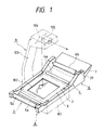
- Fig. 1 is an external perspective view of an overhead projector (OHP) employing an original feeding device
- Fig. 2 is a cross-sectional view of the original feeding device
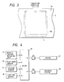
- Fig. 3 is a schematic view of a transporting film
- Fig. 4 is a block diagram of the control system of the original feeding device.
- OHP overhead projector
- Fig. 1 for explaining the entire configuration of the original feeding device A and the overhead projector B.
- the original feeding device A is mounted on the overhead projector B, indicated by chain lines in Fig. 1, and is used for automatically feeding OHP originals 1 to be used on the overhead projector B.
- the originals 1, separated one by one in the order of pages from a stack of plural originals by means of a separating-transporting mechanism to be explained later, are individually sandwiched between a conveying film 2, consisting of a web-shaped transparent film, and a pressing film 3, consisting similarly of a web-shaped transparent film, and the films 2, 3 with the originals 1 sandwiched therebetween are transported in contact with an exposure stage 101 by film transporting means 4.
- the conveying film 2 and pressing film 3 are wound on second winding means 6 and are taken up by the rotation of first winding means 6.
- the above-mentioned original 1, supported between the conveying film 2 and the pressing film 3, is transported onto a platen glass 102 provided in the exposure stage 101 of the overhead projector B.
- the original 1 is illuminated by the light from the exposure stage 101, and the transmitted light is projected on an unrepresented screen through projection means consisting of a mirror 104 and a lens 105 and supported above by an arm 103, whereby the image borne by the original is projected in magnified manner.
- a feeding tray 7 is provided for supporting a stack of the originals, which are stacked along a guide member 8, with the image-bearing faces upwards and in the increasing order of page numbers from the top to the bottom.
- a pick-up roller 9 is rotatably supported by a rocking arm 11, rotatable about a shaft 10 of a feed roller 10.
- the rocking arm 11 is rotated clockwise to press the pick-up roller 9 onto the top of the original stack, whereby the originals 1 are fed in succession from the top of the stack.
- the feed roller 10 is provided for transporting the originals 1, fed by the above-mentioned pick-up roller 9, toward the downstream side.
- a separating roller 12 is maintained in pressure contact, by means of an unrepresented spring, with the feed roller 10.
- the shaft 12a of the separating roller 12 is provided therein with a one-way clutch, which transmits clockwise rotation only to the separating roller 12.
- Each original 1 is thus separated and transported by the feed roller 10 and the separating roller 12, rotated in the same direction, and is guided by an upper transport guide 13a and a lower transport guide 13b until the front end reaches the nip of paired transport rollers 4a, 4b.
- a feed sensor 14 is provided for detecting the front and rear ends of the original 1.
- the convey film 2 and the pressing film 3 support the originals 1 by sandwiching, and are composed of web-shaped transparent films wider than the width of the originals 1.
- the films are preferably made thinner as long as enough strength can be maintained, and those of a thickness within a range of about 25 to 60 ⁇ m are preferably employed. They are preferably composed of a material of satisfactory light transmittance and stable heat resistance, and a preferred example is polyethylene terephthalate film.
- the above-mentioned convey film 2 supports the originals 1 and effects transportation thereof by the winding motion of the conveying film 2.
- the pressing film 3 presses the upper faces of the originals 1 supported on the conveying film 2, thereby preventing the lifting of the originals 1, for example, by curling, and also preventing damage to the originals 1.
- a film end mark 2a As shown in Fig. 3.
- the home position of the conveying film 2 is defined at a position where the film end mark 2a is detected by a film mark sensor 15, and the transporting operation for the originals 1 is started from the home position.
- the conveying film 2 is connected, at the ends thereof, to a first transport roller 5a mounted on the first winding means 5 and a second transport roller 6a mounted on the second winding means 6, and is maintained in close contact with the pressing film 3 at the paired film transporting rollers 4a, 4b and a tension roller 16.
- the pressing film 3 is connected, at the ends thereof, to a first pressing roller 5b provided on the first winding means 5 and a second pressing roller 6b provided on the second winding means 6, and is similarly maintained in close contact with the conveying film 2 at the paired film transporting rollers 4a, 4b and the tension roller 16.
- the upper roller 4a and the lower roller 4b are maintained in mutual contact with a pressure of 1 to 2 kgf, and serve to control the transportation of the conveying film 2 and the pressing film 3, and to extract the original 1, separated and transported as explained before, from the paired feeding-separating rollers 10, 12 and to insert thus extracted original between the conveying film 2 and the pressing film 3 for transportation.
- the first winding means 5 serves to take up an end of the web-shaped conveying film 2 and pressing film 3, and is provided, as shown in Fig. 1, outside the image reading area of the exposure stage 101 of the overhead projector B. In the present device, it is positioned, as shown in Fig. 2, at the left side of the image reading area of the exposure stage 101, and rotatably supports the first transport roller 5a for taking up the conveying film 2 and the first pressing roller 5b for taking up the pressing film 3, on front and rear frames.
- the conveying film 2 is fixed, for example, with cellophane tape, and the film 2 is taken up by the rotation of the first transporting roller 5a.
- the pressing film 3 is fixed, for example, with cellophane tape, and the film 3 is taken up by the rotation of the first pressing roller 5b.
- the second winding means 6 serves to wind the other ends of the conveying film 2 and the pressing film 3, and is provided outside the image reading area of the exposure stage 101 of the overhead projector B, as shown in Fig. 1. In the present device, it is positioned, as shown in Fig. 2, at the right side of the outside of the image reading area of the exposure stage 101, and rotatably supports, the second transporting roller 6a for winding the conveying film 2 and the second pressing roller 6b for winding the pressing film 3, by front and rear frames.
- the conveying film 2 is fixed, for example, with cellophane tape, and the conveying film 2 is taken up by the rotation of the second transporting roller 6a.
- the pressing film 3 is fixed, for example, with cellophane tape, and the pressing film 3 is taken up by the rotation of the second pressing roller 6b.
- the tension roller 16 and the paired film transporting rollers 4a, 4b mentioned above serve to tent the conveying film 2 and the pressing film 3, with the originals 1 sandwiched therebetween, in mutually contacting relationship on the platen glass 102 of the overhead projector B.
- the tension roller 16 and the paired film transporting rollers 4a, 4b are respectively provided at the left and right sides of the image reading area of the exposure stage 101.
- the pressing film 3 and the conveying film 2 are supported in succession so that the two films are maintained in mutual contact.
- the tension roller 16 is rotated by the films so that the films are protected from the scars by friction.
- a pick-up Myler member 17 is provided.
- the front end of the original 1 passes the nip between the paired film transporting rollers 4a, 4b, the front end is guided by the pick-up Myler member 17 into a discharge path.
- the paired discharge rollers 19 are activated to discharge the original 1 onto the tray 7.
- the above-mentioned paired discharge rollers 19 is composed of a driven discharge roller 19a and an idler roller 19b maintained in contact, with a light pressure, with the driven roller 19a and rotated thereby.
- a remote control unit 20 shown in Fig. 2 is provided with a forward button 20a and a reverse button 20b.
- a remote control receiving unit 21 effects driving and stopping of the original feeding device by remote control, utilizing the signals generated by the remote control unit 20.
- control unit of the original feeding device A with reference to a block diagram shown in Fig. 4.
- the control operation of the original feeding device A is principally conducted by a known one-chip microcomputer (MCOM) 36 incorporating ROM, RAM, etc.
- MCOM microcomputer
- Input ports P0 - P3 of the MCOM 36 receives signals from the above-mentioned remote control receiving unit 21 for receiving the signals from the remote control unit 20, the film mark sensor 15 for detecting the film end mark 2a on the conveying film 2, the discharge sensor 18 for detecting the fed original 1, etc.
- output ports F0, F1 of the MCOM 36 releases various output signals for turning on and off a motor 22 for driving the rollers for transporting the conveying film 2, the pressing film 3 and the originals 1, and for turning on and off the solenoid clutch 24 for controlling the gaps of the originals 1 to be transported.
- the motor 22 directly drives the paired transporting rollers 4a, 4b, the transport rollers 5a, 5b, 6a and 6b, and also drives the pick-up roller 9 and the feeding-separating rollers 10, 12 through the solenoid clutch 24.
- the fetching of the above-mentioned input signals and the on/off operations of the loads are conducted according to a program stored in the ROM associated with the MCOM 36.
- the film mark sensor 15 shown in Fig. 2 is composed of a photosensor fixed on the frame, is positioned at a position corresponding to the end portion of the conveying film 2 and detects the opaque film end mark 2a provided thereon.
- the film end mark 2a is provided at the frontmost position of the conveying film 2 within the transportable range thereof, and the home positioning of the film, at the position of the film end mark 2a, is conducted after the start of power supply.
- the solenoid clutch 24 is activated to rotate the feed roller 10 clockwise.
- the pick-up roller 9 is rotated clockwise and the rocking arm 11 is rotated clockwise about the feed roller shaft 10a to place and press the pick-up roller 9 onto the original stack.
- the originals are fed in succession, from the uppermost one, into the nip of the feed roller 10 and the separating roller 12.
- the friction coefficient ⁇ between the feed roller 10 and the original (OHP sheet) 1 is selected larger than the friction coefficient ⁇ between the separating roller 12 and the original 1, an upper original alone is transported even if two originals simultaneously enter the nip.
- the original 1 When the front end of thus separated and transported original is detected by the feed sensor 14, the original 1 is supported between the paired film transporting rollers 14. After the original 1 is subsequently transported by about 50 mm between the conveying film 2 and the pressing film 3, the solenoid clutch 24 is turned off. As the transporting force of the paired film trnasporting rollers 4a, 4b for the original 1 is selected larger than the transporting force exerted by the separating-transporting unit, the original 1 is transported by the paired rollers 4a, 4b only, after the deactivation of the solenoid clutch 24, whereby the feed roller 10 and the separating roller 12 are driven by the original 1 which is extracted from the nip of the rollers.
- the length of the original 1 is measured as the rear end thereof passes the feed sensor 14.
- the length of the original 1 can be determined by calculating the distance by the number of steps given to the motor 22 within the period from the turning-on to the turning-off of the feed sensor 14.
- the length from the rear end of the original to the center thereof is equal to a half of the length of the original 1, and the motor 22 is so controlled and stopped that the center of the original coincides with the center of the exposure stage 101 of the overhead projector B.
- the transporting operation is conducted in the following manner when the originals 1 are reversed.
- the reverse button 20b of the remote control unit 20 As the reverse button 20b of the remote control unit 20 is depressed, the motor 22 is rotated anticlockwise to rotate the upper film transporting roller 4a in the same direction, thereby transporting the conveying film 2 and the pressing film 3 to the right in Fig. 2.
- the second transport roller 6a and the second pressing roller 6b are rotated at a high speed, with slippage, to take up the conveying film 2 and the pressing film 3.
- the solenoid clutch 24 is activated to rotate the feed roller 10 anticlockwise.
- the pick-up roller 9 is rotated anticlockwise, and the rocking arm 11 is rotated anticlockwise about the feed roller shaft 10a to retract the pick-up roller 9 from the tray 7.
- the original 1 is transported toward right in Fig. 2, and, as it passes the nip of the paired film trnasporting rollers 4, the front end of the original 1 is picked up by the pick-up Myler member 17 and is guided into the discharge path.
- the paired discharge rollers 19 are activated to transport the original 1.
- the motor 22 When the original 1 is transported by a predetermined amount after the turning-on of the discharge sensor, the motor 22 is so stopped that the center of a preceding original 1 coincides with the center of the exposure stage of the overhead projector B. In this state, the original 1 is discharged and stacked on the tray 7.
- the originals 1 are stacked on the tray 7 with the proper sequence of pages and with the image-bearing faces upwards. In this manner, the sequence of pages is properly maintained and the sequential access is rendered possible in the forward or reverse feeding operation.
- the user can initiate presentation by merely operating the remote control unit 20 after placing the orignals 1, stacked in the order of pages, on the tray 7, so that the setting of the originals 1 and the preparation for presentation can be expedited.
- the user in case the user is replaced by another, he can recover the used originals 1 by discharge onto the tray 7, and the next user can change within a short time by merely placing the originals on the tray 7. Also, the originals 1 recovered on the tray 7 need not be rearranged as they are in the proper order of pages.
- the work and time required for the original setting, preparation for presentation and change of the users can be curtailed. Also, the originals can be transported or recovered without disturbing the order of pages, and smooth access to any original in the course of transportation is possible. In this manner, the convenience of use of the device is significantly improved.
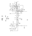
- Fig. 5 shows the configuration of an OHP original feeder (hereinafter simply called OHP feeder).
- OHP feeder is so mounted as to cover the exposure stage of the OHP 101.
- the user stacks the originals to be presented in advance on the OHP feeder, and achieve individual feeding of the originals, fine adjustment of the position of the original, discharge of the original, etc. by remote control, utilizing, for example, an infrared remote control unit (not shown).
- Numeral 1 indicates a transparent original to be projected by the overhead projector.
- a pick-up roller 9 is linked with a transporting motor 22 through a solenoid clutch 24, and separates and transports the originals from the top side.
- the separated and transported original 1 reaches the position of a registration sensor 14 through a transport path 217, then further transported to be pinched between a transparent upper transporting film 3 and a lower conveying film 2, taken up by winding rollers 5a, 5b, 6a, 6b and pinch rollers 4. Then, transported in a direction F to a display stage 102 and stopped.
- the length of the original and the position thereof in the course of transportation can be measured by the number of output pulses of a clock sensor 209 detected while the registration sensor 14' is turned on.
- the position of the original 1 thus stopped on the display stage 102 can be finely adjusted, if desired by the user, by a slight movement of the conveying films 3, 2.
- the original 1 on the display stage 102 is illuminated by a lamp 220, whereby the image of the original 1 is projected, through a lens, onto a white wall or the like.
- the original 1 after presentation is transported further in the direction F from the display stage 102 and is taken up together with the conveying film 2 by the winding roller 5a, while a next original is transported with a certain gap from the preceeding one.
- the above-mentioned operation is repeated until all the originals are presented.
- the transporting motor 22 is reversed to transport the originals in a direction R.
- the original 1 transported from the winding roller 5a passes the display stage 102, and is released from the upper and lower conveying films 3, 2 after passing the pinch roller 4.
- the original is picked upwards at the branching point of the transport paths and proceeds toward a discharge path 218.
- the original 1 Upon entering the discharge path 218, the original 1 is discharged from the device by discharge rollers 19.
- a discharge sensor 18 monitors the state of transportation of the original on the discharge path 218. This operation is conducted until all the originals are discharged.
- a home position marker, provided on the lower conveying film 2 is detected by a film marker sensor 15, whereby the home position of the conveying film can be confirmed.
- Fig. 6 is a circuit block diagram of the OHP feeder.
- the OHP feeder employs a one-chip microcomputer 223 for the control.
- the microcomputer 223 is connected to a ROM 224 storing a control program, a RAM 225 serving as a work area, a nonvolatile memory E 2 PROM 226, etc.
- Input ports of the microcomputer 223 are connected to the registration sensor 14 provided on the transport path 217, the discharge sensor 18 provided on the discharge path 218, the film marker sensor 15 for detecting the reference position of the lower transporting film, and various setting switches 221.
- an interruption port of the microcomputer 223 is connected to the clock sensor 207 for obtaining reference clock signals, indicating the amount of movement of the original, from the rotation of a clock disk 206 directly linked with the shaft of the transporting motor 22, an infrared remote control sensor 21 for receiving the key information from an infrared remote control unit, etc.
- output ports of the microcomputer 223 are connected to the transporting motor 22 and the solenoid clutch 24.
- Fig. 7 shows the principle of control of the original stopping position in the OHP feeder.
- the displayed original is usually stopped in such a manner that the center of the original coincides with the center of the display stage 102. Therefore, the amount of transportation of the original, from the position of the registration sensor 14 to the above-mentioned stopping position where the center of the original 1 coincides with the center of the display stage 102, is represented by: k 0 + (L + k)/2 wherein:
- L and k 0 are given by the configuration of the feeder, but k is variable according to the size of the original and according to whether the original is positioned vertically or laterally oblong. For this reason, k has to be measured in the course of transportation of the original.
- Fig. 8 shows the state of the outputs of the registration sensor 14 and the clock sensor 207, in the course of transportation of the original.
- the transporting operation can, therefore, be controlled by determining an appropriate amount of transportation of the original from thus measured length of the original.
- Figs. 9 and 10 show the principle of control on the gap between the originals.
- the start of the transporting operation for the next original can be controlled with a timing corresponding to thus determined gap.
- Fig. 11 shows a driving circuit for the transporting motor.
- the driving circuit is composed of a transistor bridge circuit for rotating the transporting motor in the forward and reverse directions.
- the transporting speed of the original can be regulated by suitably varying the pulse width of the ON signal for the switching transistor Q5.
- the fine adjustment of the position of the original in the forward direction can be achieved by activating the transporting motor for a short period with a low transporting speed, and monitoring the number of the clock pulses.
- the original transporting operation in the reverse direction can be achieved in a similar manner as explained above, with a motor current I M in a direction from A to B.
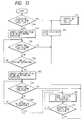
- Fig. 13 shows a flow chart for checking the remaining original at the start of power supply.
- the conveying film 2 is not in the home position, there is initiated a searching operation for the home position marker of the trnasporting film.
- the conveying film is advanced in the forward direction by an amount M (S54). If the home position marker can be detected during said advancement (S56), the conveying films 3, 2 are stopped at the timing of said detection (S58), and there is entered the stand-by state for the operation signals from the infrared remote control unit (S52).
- the conveying films 3, 2 are stopped and the forward transporting operation is terminated (S60). Then, the conveying films 3, 2 are moved in the reverse direction by an amount 2M (S62). If the home position marker can be detected during the movement (S64), the conveying films 3, 2 are stopped at the timing of the detection, and there is entered the stand-by state for the operation signals from the infrared remote control unit (S52).
- Fig. 12 shows another embodiment of the driving circuit for the transporting motor.
- the driving circuit is composed of a transistor bridge circuit for rotating the transporting motor in the forward and reverse directions.
- the voltage supplied to the transporting motor can be lowered in effective value, by PWM control of the ON signal for the transistor Q2. In this manner, the revolution of the transporting motor can be arbitrarily controlled.
- the transporting speed of the original can be regulated by suitably varying the pulse width of the ON signal for the transistor Q2.
- the fine adjustment of the position of the original in the forward direction can be achieved by releasing the pulsed ON signal for the transistor Q2, for a short period.
- the original transporting operation in the reverse direction can be achieved in a similar manner as explained above, with a motor current I M in a direction from A to B.
- Fig. 14 is a flow chart showing another embodiment for checking the remaining original at the start of power supply.
- a remaining original flag "1" is set in the E 2 PROM 26 (step S80).
- the flag is set as "1" when an original is transported and wound, and is reset to "0" when all the originals are discharged (S90).
- the initializing operation is completed when the above-mentioned flag is set at "0" at the discharge of all the originals (S100). Then, there is entered a stand-by state for the operation (S200).
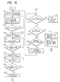
- the CPU analyzes the operation signal to identify a single feed mode, a fine adjustment mode or an all original discharging mode, whereupon a corresponding command is released to execute a corresponding sequence.
- the original 1 continues transportation as it is supported between the upper and lower conveying films 3, 2.
- the registration sensor When the rear end of the original is detected by the registration sensor, there is determined the length of the originals, and, upon counting a pulse number required for placing the original at the center of the display stage (S800), the transporting motor is turned off (S1000).
- the transporting speed for such single feeding operation can be selected from plural speeds selected in advance.
- a step S1100 discriminates whether the fine adjustment mode has been selected, and, if selected, the sequence proceeds to a step S1500 for effecting the fine adjusting operation. If the fine adjustment mode has not been selected, the sequence proceeds to a step S1200 for discriminating whether a next original is to be fed. If not, the sequence further proceeds to a step S1300 for discriminating if the original discharge mode has been selected, and, if the original discharge mode has been selected, the sequence proceeds to a step S1400 for effecting the discharge of the originals, and then the sequence returns to the step S100.
- the sequence returns to the step S1100. Also, if the next original feeding operation is selected in the step S1200, the sequence proceeds to a step S1600 for processing the conveying films, and a step S1700 for counting the originals and discriminating whether all the originals have been processed, and then the sequence returns to the step S400.
- the entire OHP feeder is controlled in the above-explained manner.
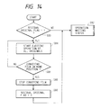
- a step S100 effects the process for the conveying film
- a step S150 sets a number for the clock pulses required for the fine adjustment.
- the pulse number in this step can be arbitrarily selected.
- a step S200 discriminates whether the counting operation of the clock pulses has been completed, and, if not, the completion of the counting operation is awaited.
- the sequence proceeds to a step S250 for the end process of the transporting film.
- the fine adjustment mode is conducted in this manner.
- the display position of the original can be finely adjusted according to the requirement of the user.
- the original transporting speed can be set in plural levels, it is rendered possible to select an appropriate transporting speed, in consideration of the comfort of the observers or of the time available for presentation.
- the presentation can be achieved without misunderstanding of the user, as the system can be controlled without complexity in the key configuration of a remote transmitting unit.
Landscapes
- Physics & Mathematics (AREA)
- General Physics & Mathematics (AREA)
- Delivering By Means Of Belts And Rollers (AREA)
- Overhead Projectors And Projection Screens (AREA)
- Holders For Sensitive Materials And Originals (AREA)
Claims (6)
- Vorlagenzufuhrvorrichtung zum aufeinanderfolgenden Zuführen einer Mehrzahl von Vorlagen (1) zu einem Anzeigen-Objekttisch (101) eines Projiziergeräts zum Projizieren eines Bilds einer auf den Anzeige-Objekttisch (101) gesetzten Vorlage (1), wobei der Anzeige-Objekttisch (101) in der Zufuhrrichtung eine Länge aufweist, die größer als die Länge der Vorlagen in der Zufuhrrichtung ist, wobei die Vorlagenzufuhrvorrichtung folgendes umfasst:dadurch gekennzeichnet, dasseine Transporteinrichtung (4) zum aufeinanderfolgenden Transportieren der Mehrzahl von Vorlagen (1) stückweise auf den Anzeige-Objekttisch (101);eine Vorlagenlängenerfassungseinrichtung (14,22) zum Erfassen der Länge jeder der Vorlagen (1) in der Vorlagentransportrichtung; undeine Steuereinrichtung (36, 223) zum Deaktivieren der Transporteinrichtung (4), nachdem die Transporteinrichtung (4) das Vorderende einer der Vorlagen (1) um einen Betrag hinter den Endabschnitt des Anzeige-Objekttisches (101) transportiert hat, der der Summe einer Hälfte der Länge des Anzeige-Objekttisches (101) und einer Hälfte der Länge der durch die Vorlagenlängenerfassungseinrichtung (14, 22) erfassten Vorlage (1) entspricht,
die Steuereinrichtung (36, 223) so angeordnet ist, dass sie den Abstand vom Hinterende einer vorangehenden Vorlage (1) auf dem Anzeige-Objekttisch (101) zum Vorderende der nachfolgenden Vorlage (1) durch das Ergebnis der Berechnung, bei der die Hälfte der Länge der durch die Vorlagenerfassungseinrichtung (14, 22) erfassten vorangehenden Vorlage (1) von der Hälfte der Länge des Anzeige-Objekttisches (101) abgezogen wird, und durch Steuern der Transporteinrichtung (4) entsprechend der Berechnung setzt. - Vorlagenzufuhrvorrichtung nach Patentanspruch 1, weiterhin mittransparenten Bändern (2, 3), zwischen die die Vorlagen (1) gelegt werden, und die durch die Transporteinrichtung (4) transportiert werden,Walzen (5a, 5b, 6a, 6b) zum Aufwickeln der Bänder (2, 3) undeiner Erfassungseinrichtung (15) zum Erfassen einer Markierung (2a) eines der Bänder (2, 3); wobeidie Steuereinrichtung so angeordnet ist, dass sie bewirkt, dass die Erfassungseinrichtung die Markierung erfasst, indem die Walzen (5a, 5b, 6a, 6b) beim Start der Leistungszufuhr zur Vorlagenzufuhrvorrichtung in der Vorwärts- oder Rückwärtsrichtung um einen vorbestimmten Betrag gedreht werden.
- Vorlagenzufuhrvorrichtung nach Patentanspruch 1, weiterhin mit
einer Einstelleinrichtung zum Feineinstellen einer Stopp-Position der Vorlage (1) auf dem Anzeige-Objekttisch (101). - Vorlagenzufuhrvorrichtung nach Patentanspruch 1, weiterhin mit
einer Auswahleinrichtung zum Auswählen einer Transportgeschwindigkeit der Transporteinrichtung aus einer Mehrzahl von Geschwindigkeiten, wobei die Transporteinrichtung so angeordnet ist, dass sie die Vorlagen (1) mit der durch die Auswahleinrichtung ausgewählten Geschwindigkeit transportiert. - Vorlagenzufuhrvorrichtung nach Patentanspruch 1, wobei die Vorlagen (1) Transparentfolien sind.
- Vorlagenzufuhrvorrichtung nach Patentanspruch 1, wobei das Projiziergerät ein Overhead-Projektor (B) ist.
Applications Claiming Priority (6)
| Application Number | Priority Date | Filing Date | Title |
|---|---|---|---|
| JP20007393 | 1993-07-19 | ||
| JP5200073A JP2955160B2 (ja) | 1993-07-19 | 1993-07-19 | 原稿搬送装置及びオーバーヘッドプロジェクター |
| JP200073/93 | 1993-07-19 | ||
| JP180355/93 | 1993-07-21 | ||
| JP18035593A JPH0733282A (ja) | 1993-07-21 | 1993-07-21 | 原稿搬送装置 |
| JP18035593 | 1993-07-21 |
Publications (2)
| Publication Number | Publication Date |
|---|---|
| EP0635751A1 EP0635751A1 (de) | 1995-01-25 |
| EP0635751B1 true EP0635751B1 (de) | 2001-01-17 |
Family
ID=26499909
Family Applications (1)
| Application Number | Title | Priority Date | Filing Date |
|---|---|---|---|
| EP94111154A Expired - Lifetime EP0635751B1 (de) | 1993-07-19 | 1994-07-18 | Vorlagenzuführgerät |
Country Status (3)
| Country | Link |
|---|---|
| US (1) | US5526077A (de) |
| EP (1) | EP0635751B1 (de) |
| DE (1) | DE69426582T2 (de) |
Citations (5)
| Publication number | Priority date | Publication date | Assignee | Title |
|---|---|---|---|---|
| JPS59127023A (ja) * | 1983-01-11 | 1984-07-21 | Fuji Xerox Co Ltd | オ−バ−ヘツドプロジエクタ− |
| JPS6295573A (ja) * | 1985-10-23 | 1987-05-02 | Ricoh Co Ltd | 複写装置 |
| US4671648A (en) * | 1986-07-11 | 1987-06-09 | Fuji Photo Film Co., Ltd. | Image data processing apparatus |
| US4727393A (en) * | 1985-10-18 | 1988-02-23 | Fuji Photo Film Co., Ltd. | Processing head for electrophotographic apparatus |
| US4944586A (en) * | 1989-11-30 | 1990-07-31 | E. I. Du Pont De Nemours And Company | Automated transparency organizer |
Family Cites Families (11)
| Publication number | Priority date | Publication date | Assignee | Title |
|---|---|---|---|---|
| US3317151A (en) * | 1963-07-19 | 1967-05-02 | John S Wright | Projection stage apparatus |
| DE1281836B (de) * | 1966-12-12 | 1968-10-31 | Reprotechnik Leipzig Veb | Reproduktionskamera mit Speichereinrichtung fuer die Vorlagen |
| US3594082A (en) * | 1969-07-31 | 1971-07-20 | Thomas M Lonchar | Slide changer for an overhead projector |
| US4050816A (en) * | 1976-06-30 | 1977-09-27 | Xerox Corporation | Document handling system |
| SE410661B (sv) * | 1978-03-03 | 1979-10-22 | Lindqvist Inger Merethe | Bildvexlingsanordning for storbildsprojektorer |
| JPS62258437A (ja) * | 1986-05-01 | 1987-11-10 | Shinko Electric Co Ltd | オ−バ−ヘツドプロジエクタ−用原稿移送装置 |
| JP2521788B2 (ja) * | 1987-05-19 | 1996-08-07 | 富士写真フイルム株式会社 | 自動原稿送り装置 |
| EP0421330B1 (de) * | 1989-10-02 | 1995-07-05 | Canon Kabushiki Kaisha | Blattzufuhrgerät |
| FR2656433B1 (fr) * | 1989-12-22 | 1992-05-07 | Genieis Jean | Dispositifs pour alimenter automatiquement un projecteur d'images. |
| US5172145A (en) * | 1990-12-21 | 1992-12-15 | Eastman Kodak Company | Bidirectional, cassette-loaded changer mechanism for overhead transparencies |
| US5339122A (en) * | 1993-11-12 | 1994-08-16 | Pelikan, Inc. | Overhead projector with automatic document positioner |
-
1994
- 1994-07-14 US US08/273,134 patent/US5526077A/en not_active Expired - Lifetime
- 1994-07-18 EP EP94111154A patent/EP0635751B1/de not_active Expired - Lifetime
- 1994-07-18 DE DE69426582T patent/DE69426582T2/de not_active Expired - Fee Related
Patent Citations (5)
| Publication number | Priority date | Publication date | Assignee | Title |
|---|---|---|---|---|
| JPS59127023A (ja) * | 1983-01-11 | 1984-07-21 | Fuji Xerox Co Ltd | オ−バ−ヘツドプロジエクタ− |
| US4727393A (en) * | 1985-10-18 | 1988-02-23 | Fuji Photo Film Co., Ltd. | Processing head for electrophotographic apparatus |
| JPS6295573A (ja) * | 1985-10-23 | 1987-05-02 | Ricoh Co Ltd | 複写装置 |
| US4671648A (en) * | 1986-07-11 | 1987-06-09 | Fuji Photo Film Co., Ltd. | Image data processing apparatus |
| US4944586A (en) * | 1989-11-30 | 1990-07-31 | E. I. Du Pont De Nemours And Company | Automated transparency organizer |
Non-Patent Citations (2)
| Title |
|---|
| PATENT ABSTRACTS OF JAPAN vol. 11, no. 303 (P - 622) 3 October 1987 (1987-10-03) * |
| PATENT ABSTRACTS OF JAPAN vol. 8, no. 257 (P - 316) 24 November 1984 (1984-11-24) * |
Also Published As
| Publication number | Publication date |
|---|---|
| DE69426582T2 (de) | 2001-06-07 |
| EP0635751A1 (de) | 1995-01-25 |
| US5526077A (en) | 1996-06-11 |
| DE69426582D1 (de) | 2001-02-22 |
Similar Documents
| Publication | Publication Date | Title |
|---|---|---|
| US4803505A (en) | Microfilm camera | |
| EP0635751B1 (de) | Vorlagenzuführgerät | |
| US5444506A (en) | Projection original film feeding apparatus | |
| JP3010091B2 (ja) | シート反転装置 | |
| US5446511A (en) | Original conveying apparatus | |
| US5365323A (en) | Image recording device | |
| JPH06138734A (ja) | 自動原稿搬送装置 | |
| US4029411A (en) | Variable magnification copier | |
| US5448345A (en) | Sheet original conveying apparatus and image forming apparatus with it | |
| JP3498243B2 (ja) | 原稿搬送装置 | |
| US4901108A (en) | Microfilming apparatus | |
| JPS60114876A (ja) | 画像形成装置 | |
| JP3205608B2 (ja) | シート搬送装置 | |
| JP3419706B2 (ja) | フィルムシートの処理装置 | |
| US4914744A (en) | Microfilming apparatus | |
| JP3445005B2 (ja) | 原稿自動送り装置 | |
| JPH07114228A (ja) | 原稿搬送装置及び投影装置 | |
| JPH043138A (ja) | マイクロフィルム・リーダプリンタの露光量制御装置 | |
| JPH0822073A (ja) | オーバヘッドプロジェクタ原稿フィーダ装置及びオーバヘッドプロジェクタ | |
| JPH01197730A (ja) | ロールフイルムキャリア | |
| JPH0733282A (ja) | 原稿搬送装置 | |
| JPH0728167A (ja) | 原稿搬送装置及びオーバーヘッドプロジェクター | |
| JPH07281321A (ja) | 原稿搬送装置 | |
| JPH06255835A (ja) | 自動原稿送り装置 | |
| JPH07114117A (ja) | 原稿搬送装置及び投影装置 |
Legal Events
| Date | Code | Title | Description |
|---|---|---|---|
| PUAI | Public reference made under article 153(3) epc to a published international application that has entered the european phase |
Free format text: ORIGINAL CODE: 0009012 |
|
| AK | Designated contracting states |
Kind code of ref document: A1 Designated state(s): DE ES FR GB IT NL |
|
| 17P | Request for examination filed |
Effective date: 19950612 |
|
| 17Q | First examination report despatched |
Effective date: 19981113 |
|
| GRAG | Despatch of communication of intention to grant |
Free format text: ORIGINAL CODE: EPIDOS AGRA |
|
| 17Q | First examination report despatched |
Effective date: 19981113 |
|
| GRAG | Despatch of communication of intention to grant |
Free format text: ORIGINAL CODE: EPIDOS AGRA |
|
| GRAH | Despatch of communication of intention to grant a patent |
Free format text: ORIGINAL CODE: EPIDOS IGRA |
|
| GRAH | Despatch of communication of intention to grant a patent |
Free format text: ORIGINAL CODE: EPIDOS IGRA |
|
| GRAA | (expected) grant |
Free format text: ORIGINAL CODE: 0009210 |
|
| AK | Designated contracting states |
Kind code of ref document: B1 Designated state(s): DE ES FR GB IT NL |
|
| PG25 | Lapsed in a contracting state [announced via postgrant information from national office to epo] |
Ref country code: NL Free format text: LAPSE BECAUSE OF FAILURE TO SUBMIT A TRANSLATION OF THE DESCRIPTION OR TO PAY THE FEE WITHIN THE PRESCRIBED TIME-LIMIT Effective date: 20010117 Ref country code: IT Free format text: LAPSE BECAUSE OF FAILURE TO SUBMIT A TRANSLATION OF THE DESCRIPTION OR TO PAY THE FEE WITHIN THE PRE;WARNING: LAPSES OF ITALIAN PATENTS WITH EFFECTIVE DATE BEFORE 2007 MAY HAVE OCCURRED AT ANY TIME BEFORE 2007. THE CORRECT EFFECTIVE DATE MAY BE DIFFERENT FROM THE ONE RECORDED.SCRIBED TIME-LIMIT Effective date: 20010117 Ref country code: FR Free format text: LAPSE BECAUSE OF FAILURE TO SUBMIT A TRANSLATION OF THE DESCRIPTION OR TO PAY THE FEE WITHIN THE PRESCRIBED TIME-LIMIT Effective date: 20010117 Ref country code: ES Free format text: THE PATENT HAS BEEN ANNULLED BY A DECISION OF A NATIONAL AUTHORITY Effective date: 20010117 |
|
| REF | Corresponds to: |
Ref document number: 69426582 Country of ref document: DE Date of ref document: 20010222 |
|
| RIN2 | Information on inventor provided after grant (corrected) |
Free format text: SATO, SHUNJI, C/O CANON KABUSHIKI KAISHA * HAYAKAWA, KIMIAKI, C/O CANON KABUSHIKI KAISHA * KITAHARA, YOSHIHIKO, C/O CANON APTEX INC. * IIZUMI, KENICHI, C/O CANON APTEX INC. * NAKAZAWA, NORIAKI |
|
| EN | Fr: translation not filed | ||
| NLV1 | Nl: lapsed or annulled due to failure to fulfill the requirements of art. 29p and 29m of the patents act | ||
| PG25 | Lapsed in a contracting state [announced via postgrant information from national office to epo] |
Ref country code: GB Free format text: LAPSE BECAUSE OF NON-PAYMENT OF DUE FEES Effective date: 20010718 |
|
| PLBE | No opposition filed within time limit |
Free format text: ORIGINAL CODE: 0009261 |
|
| STAA | Information on the status of an ep patent application or granted ep patent |
Free format text: STATUS: NO OPPOSITION FILED WITHIN TIME LIMIT |
|
| 26N | No opposition filed | ||
| GBPC | Gb: european patent ceased through non-payment of renewal fee |
Effective date: 20010718 |
|
| PGFP | Annual fee paid to national office [announced via postgrant information from national office to epo] |
Ref country code: DE Payment date: 20080724 Year of fee payment: 15 |
|
| PG25 | Lapsed in a contracting state [announced via postgrant information from national office to epo] |
Ref country code: DE Free format text: LAPSE BECAUSE OF NON-PAYMENT OF DUE FEES Effective date: 20100202 |