EP0632908B1 - Vorrichtung zum lösbaren befestigen einer fixierwalze auf einem lagerflansch einer fixierstation eines elektrofotografischen druck- oder kopiergerätes - Google Patents
Vorrichtung zum lösbaren befestigen einer fixierwalze auf einem lagerflansch einer fixierstation eines elektrofotografischen druck- oder kopiergerätes Download PDFInfo
- Publication number
- EP0632908B1 EP0632908B1 EP93905178A EP93905178A EP0632908B1 EP 0632908 B1 EP0632908 B1 EP 0632908B1 EP 93905178 A EP93905178 A EP 93905178A EP 93905178 A EP93905178 A EP 93905178A EP 0632908 B1 EP0632908 B1 EP 0632908B1
- Authority
- EP
- European Patent Office
- Prior art keywords
- bearing flange
- fixing
- fuser roller
- bearing
- receiving
- Prior art date
- Legal status (The legal status is an assumption and is not a legal conclusion. Google has not performed a legal analysis and makes no representation as to the accuracy of the status listed.)
- Expired - Lifetime
Links
Images

Classifications
-
- G—PHYSICS
- G03—PHOTOGRAPHY; CINEMATOGRAPHY; ANALOGOUS TECHNIQUES USING WAVES OTHER THAN OPTICAL WAVES; ELECTROGRAPHY; HOLOGRAPHY
- G03G—ELECTROGRAPHY; ELECTROPHOTOGRAPHY; MAGNETOGRAPHY
- G03G15/00—Apparatus for electrographic processes using a charge pattern
- G03G15/20—Apparatus for electrographic processes using a charge pattern for fixing, e.g. by using heat
- G03G15/2003—Apparatus for electrographic processes using a charge pattern for fixing, e.g. by using heat using heat
- G03G15/2014—Apparatus for electrographic processes using a charge pattern for fixing, e.g. by using heat using heat using contact heat
- G03G15/2053—Structural details of heat elements, e.g. structure of roller or belt, eddy current, induction heating
Definitions
- thermal fixing stations In electrophotographic printing or copying devices, it is customary to fix the recording medium coated with toner in a thermal fixing station.
- thermal fixing stations generally contain electrically heated fixing rollers with associated pressure rollers that can be pivoted on and off.
- the record carrier is passed between the fixing roller and the pressure roller for fixing.
- the toner is fixed on the recording medium by the action of heat from the fixing roller. Since the toner has to be brought to the melting temperature during the short contact distance of the recording medium with the fixing roller, a high heating output on the part of the fixing roller is necessary.
- halogen lamps with high heating power in the hollow fixing roller. Both the halogen lamps in the fixing roller and the fixing roller itself are subject to wear, so that it is necessary from time to time to replace the halogen lamps and the fixing roller.
- the object of the invention is therefore to provide a device for releasably fastening a fixing roller on a bearing flange of a fixing station of an electrophotographic printing or copying device, which enables the bearing flange and fixing roller to be connected to one another or detached from one another, even if the fixing roller and the bearing flange are different Have temperatures.
- the fixing roller receiving flanges are assigned collet-like receiving bushes which have an internal conical bore.
- the receptacles are seated on an expansion element which plunges into the conical bores in the form of a counter cone.
- a clamping ring encompassing the receiving bushes presses the receiving bushes radially resiliently against the mating cone of the expansion elements.
- the receiving bushes themselves in turn have an external contact surface for contacting an inner radius of the fixing roller, a spring element pressing the receiving bushes axially against a stop of the fixing roller. This creates an effective recording diameter of the bearing flange, which is smaller than the inside diameter of the fixing roller.
- the fuser roller can be easily pushed onto the flanges. By axially bracing the flanges, the mounting bushes are spread over the counter cone and a clamping connection between the fixing rollers and the bearing flange is created.
- a detachable bearing flange on the operator side is loosened, thus relieving the axially tensioned fastening system.
- the diameter of the mounting bushes is reduced by the spring and the clamping ring, which means that the fixing roller can be easily removed from the device via the detachable bearing flange.
- a fixing station of an electrophotographic printing device known from FIG. 2 and shown in FIG. 2 contains a fixing roller or heating roller 11, which is mounted on a frame 10 of the printing device, and a pressure roller, not shown here.
- the heating roller 11 consists of an aluminum tube 13 coated with Teflon 12, which is open on both sides.
- the heating roller 11 is mounted in the frame 10 of the fixing station, on one side via a bearing flange 14 with a central holding and guiding opening 15 and on the other hand via a bearing element 16 which is connected to a drive device 17 in the form of a belt wheel 18 which is only shown schematically here.
- a bearing 19/1 is located on the bearing flange 14 and engages with a centering piece 20 in the aluminum tube 13 of the heating roller 11.
- the other bearing element 16 with bearing 19/2 on the drive side of the fixing station also has a centering projection 21 which engages in the other side of the aluminum tube 13 of the heating roller 11.
- plate springs 22 are arranged on the bearing element 16, which engage the heating roller via a disk 22/1 and press against the centering piece 20 of the bearing flange 14. They ensure the compensation of the axial thermal expansion.
- the aluminum tube of the heating roller 11 slides on the centering shoulder 21, the disc 22/1 being connected to the centering shoulder 21 by screws 21/1.
- a driver part 23 on the bearing element 16 engages in a corresponding recess in the aluminum tube 13 of the heating roller 11 and thus ensures a secure drive connection.
- the bearing flange 14 is detachably connected to the frame 10 of the fixing station via wing screws 24.
- the heating roller 11 is secured with respect to the bearing flange 14 with the aid of holding claws 26 fastened via wing screws 25.
- the holding claw 26 has a projection 27 which engages in a groove 28 of the heating roller, the projection 27 not touching the groove 28 in the installed state, so that the heating roller 11 can move radially freely.
- the holding claw 26 has a securing function for exchanging the fixing roller 11.
- the wing screws 24 are loosened and the fixing roller 11, together with the flange 14, can be secured and removed from the frame 10 of the fixing station by the holding claws 26 with the aid of a handle 29 fastened to the bearing flange 14.
- a retaining ring 24/1 receiving the wing screws 24 is covered on the inside with felt 24/2.
- radiator module 30 consisting of several, e.g. two halogen spotlights arranged one above the other. This radiator module is also designed to be interchangeable.
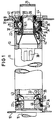
- the device shown in FIG. 1 can be used to replace the fixing roller even in the hot state without having to observe a cooling time.
- FIGS. 1 and 2 are identified with identical reference numerals.
- Both the detachable bearing flange 14 on the operator side and the bearing flange 16 (bearing element) fixed to the frame have a conical expansion element 31 or 31a.
- the expansion elements 31, 31a are each encompassed by receiving bushes 32 and 32a, which are resilient and which have an inner counter cone 33 and an outer contact surface 34.
- the receiving bushes 32, 32a are made of bronze and have a heat-resistant sliding layer made of plastic, for example made of Teflon, on their counter cone 33.
- the receiving bushes 32 are encompassed by a clamping ring 35.
- expansion elements 31, 31a and receiving bushes 32, 32a are assigned to the bearing flanges 14 and 16, respectively. However, it is also possible to assign the receiving bushes 32, 32a to the fixing roller 11 and the expansion elements 31, 31a to the bearing flange.
- Receptacle 32 and expansion element 31 are rotatably supported on the detachable bearing flange 14 on a holder 36, which in turn is axially displaceably guided on a guide 37 of the bearing flange 14.
- spring elements 38 are arranged, which serve to compensate for the thermal axial movement of the fixing roller. According to their function, these correspond to the plate springs 22 of the device in FIG.
- the bearing is secured by locking screws 39. It is located in a bearing cage, which is formed by the expansion element 31 and a locking washer 40. Lock washer 40 and expansion element 31 are connected to one another via locking screws 41.
- a receptacle 42 for collecting abrasion and lubrication losses from the bearing is formed on the holder 36.
- the receptacles 32, 32a are seated on the expansion elements 31, 31a so that they can move axially, with locking lugs 43 formed on the expansion elements 31, 31a securing the receptacles 32, 32a on the expansion elements 31, 31a.
- Compression spring elements 44 for example in the form of a corrugated spring, are arranged between the receiving bushes 32, 32a and expansion elements 31, 31a and, in the installed state of the fixing roller shown in FIG. 1, press the receiving bushes 32, 32a via stops 45 against stop faces 46 (edge) of the fixing roller 11 .
- the compression spring elements 44 are tensioned when a clamp connection is created by immersing the expansion elements 31, 31a in the receiving bushes 32, 32a when the bearing flange 14 is screwed onto the frame 10.
- the compression spring elements 44 axially move the receiving bushes 32, 32a on the expansion elements 31, 31a. This reduces the receiving radius for receiving the fixing roller, ie the receiving diameter for the fixing roller formed by the receiving bushing is approximately 1 mm smaller than the inside diameter the fuser roller. This enables the bearing flange to be easily inserted into the fixing roller and the bearing flange to be released from the fixing roller under all thermal conditions.
- the fixing roller 11 is fastened axially clamped in the frame 10 via the bearing flanges 14 and 16.
- the expansion elements 31, 31a press the receiving bushes 32, 32a against an inner radius of the fixing roller 11 and thus ensure a rotatable clamping connection between the bearing flanges 14 and 16 and the fixing roller.
- the operator-side bearing flange 14 is detached from the frame 10 via the wing screws 24 analogously to the known device in FIG.
- the fastening system relaxes axially and, via the receiving bushes 32, 32a, the receiving radius of the bearing flanges 4 and 16 for the fixing roller is reduced in the manner described.
- the fixing roller 11 together with the flange 14, secured by the holding claws 26, can now be pulled out of the frame 10 of the fixing station with the aid of the handle 29 attached to the bearing flange 14.
- the bearing flange 14 can be detached from the fixing roller. Thereafter, the bearing flange 14 is placed on a new, cold fixing roller which is ready and secured with the aid of the holding claws 26.
- the new cold fixing roller can then be inserted into the fixing station with the aid of the handle element 29 attached to the bearing flange 14 and placed on the bearing flange 16 fixed to the frame.
- the bearing flange 16 remaining in the frame 10 is still warm, due to the displacement of the receiving bush 32a in the bearing flange 16, it has a smaller receiving radius than the fixing roller and can therefore easily accommodate the fixing roller.
- the fixing roller between the bearing flanges 14 and 16 is clamped axially and thus the required clamping connection between the bearing flanges and the fixing roller is generated.
Landscapes
- Physics & Mathematics (AREA)
- General Physics & Mathematics (AREA)
- Rolls And Other Rotary Bodies (AREA)
- Fixing For Electrophotography (AREA)
Applications Claiming Priority (3)
| Application Number | Priority Date | Filing Date | Title |
|---|---|---|---|
| DE4209520A DE4209520C1 (it) | 1992-03-24 | 1992-03-24 | |
| DE4209520 | 1992-03-24 | ||
| PCT/DE1993/000222 WO1993019401A1 (de) | 1992-03-24 | 1993-03-10 | Vorrichtung zum lösbaren befestigen einer fixierwalze auf einem lagerflansch einer fixierstation eines elektrofotografischen druck- oder kopiergerätes |
Publications (2)
| Publication Number | Publication Date |
|---|---|
| EP0632908A1 EP0632908A1 (de) | 1995-01-11 |
| EP0632908B1 true EP0632908B1 (de) | 1996-09-18 |
Family
ID=6454873
Family Applications (1)
| Application Number | Title | Priority Date | Filing Date |
|---|---|---|---|
| EP93905178A Expired - Lifetime EP0632908B1 (de) | 1992-03-24 | 1993-03-10 | Vorrichtung zum lösbaren befestigen einer fixierwalze auf einem lagerflansch einer fixierstation eines elektrofotografischen druck- oder kopiergerätes |
Country Status (5)
| Country | Link |
|---|---|
| US (1) | US5583624A (it) |
| EP (1) | EP0632908B1 (it) |
| JP (1) | JPH07504961A (it) |
| DE (2) | DE4209520C1 (it) |
| WO (1) | WO1993019401A1 (it) |
Families Citing this family (3)
| Publication number | Priority date | Publication date | Assignee | Title |
|---|---|---|---|---|
| DE19922986B4 (de) * | 1999-05-19 | 2006-01-12 | OCé PRINTING SYSTEMS GMBH | Vorrichtung und Verfahren zum Halten einer Trommel in einem Drucker oder Kopierer |
| JP5402408B2 (ja) | 2009-08-31 | 2014-01-29 | 株式会社リコー | 定着装置用ローラ、定着装置、画像形成装置、定着装置のローラ交換補助具、定着装置のローラ交換方法 |
| JP5532963B2 (ja) * | 2010-01-27 | 2014-06-25 | 株式会社リコー | 定着装置ならびにそれを備えた画像形成装置 |
Family Cites Families (7)
| Publication number | Priority date | Publication date | Assignee | Title |
|---|---|---|---|---|
| US3794417A (en) * | 1972-12-21 | 1974-02-26 | Ibm | High speed printing system with heated roll fuser |
| US3990391A (en) * | 1975-03-19 | 1976-11-09 | Addressograph Multigraph Corporation | Mounting for pressure fixing rollers |
| US3989372A (en) * | 1975-07-07 | 1976-11-02 | International Business Machines Corporation | Photoconductor cleaning stations |
| US4229950A (en) * | 1979-03-02 | 1980-10-28 | Eastman Kodak Company | Coupling for end gudgeon and internally heated roller |
| US4800644A (en) * | 1983-02-18 | 1989-01-31 | Ralph Muellenberg | Method for fastening or loosening a clamp unit |
| FI83244C (fi) * | 1987-09-16 | 1991-06-10 | Tampella Oy Ab | Pressvals foer pappersmaskin eller liknande. |
| JPH05504633A (ja) * | 1989-12-13 | 1993-07-15 | オーセ プリンテイング システムズ ゲゼルシャフト ミット ベシュレンクテル ハフツング | 電子写真式の印刷装置または複写装置に用いられる定着ステーション |
-
1992
- 1992-03-24 DE DE4209520A patent/DE4209520C1/de not_active Expired - Fee Related
-
1993
- 1993-03-10 EP EP93905178A patent/EP0632908B1/de not_active Expired - Lifetime
- 1993-03-10 JP JP5516159A patent/JPH07504961A/ja active Pending
- 1993-03-10 WO PCT/DE1993/000222 patent/WO1993019401A1/de active IP Right Grant
- 1993-03-10 US US08/302,687 patent/US5583624A/en not_active Expired - Lifetime
- 1993-03-10 DE DE59303884T patent/DE59303884D1/de not_active Expired - Fee Related
Also Published As
| Publication number | Publication date |
|---|---|
| WO1993019401A1 (de) | 1993-09-30 |
| DE4209520C1 (it) | 1993-04-08 |
| EP0632908A1 (de) | 1995-01-11 |
| DE59303884D1 (de) | 1996-10-24 |
| US5583624A (en) | 1996-12-10 |
| JPH07504961A (ja) | 1995-06-01 |
Similar Documents
| Publication | Publication Date | Title |
|---|---|---|
| EP0505404B1 (de) | Fixierstation für eine elektrofotografische druck- oder kopiereinrichtung | |
| DE4412509C2 (de) | Heizrollen-Fixiervorrichtung | |
| DE69721170T2 (de) | Elektrofotografischer Bilderzeugungsapparat und Kupplungsteil für fotoempfindliche Trommel | |
| DE60124976T2 (de) | Modularer Bremsmechanismus | |
| DE69322658T2 (de) | Plattenklemmgerät | |
| DE69109338T2 (de) | Schneidscheibespindel, insbesondere für Teilmaschinen. | |
| EP0638855A1 (de) | Wärmefixiereinrichtung für ein- oder beidseitig bedruckte Aufzeichnungsträger eines Druck- oder Kopiergerätes | |
| EP0632908B1 (de) | Vorrichtung zum lösbaren befestigen einer fixierwalze auf einem lagerflansch einer fixierstation eines elektrofotografischen druck- oder kopiergerätes | |
| EP0500002B1 (de) | Laseroptik | |
| WO1994009411A1 (de) | Trennmitteldosiervorrichtung für eine fixierwalze eines druck- oder kopiergerätes | |
| DE19717379A1 (de) | Drahtsäge und Montagestation für eine Drahtführungsrolle einer Drahtsäge sowie Verfahren zum Auswechseln einer Drahtführungsrolle | |
| DE19922986B4 (de) | Vorrichtung und Verfahren zum Halten einer Trommel in einem Drucker oder Kopierer | |
| DE112020001887B4 (de) | Pneumatischer Kupplungssteller mit Selbsteinstellmechanismus | |
| DE212017000184U1 (de) | Vorrichtung zum Ultraschallschweißen und Sonotrode für eine solche Vorrichtung | |
| EP0596399B1 (de) | Spannvorrichtung für in einer galvanischen Anlage zu bearbeitende Tiefdruckzylinder | |
| DE2653519C2 (de) | Reinigungseinrichtung für die Fixierwalze eines Druckfixierwalzenpaares in einem elektrostatischen Kopiergerät | |
| DE3941193C2 (it) | ||
| DE69228860T2 (de) | 180 Grad schwenkbarer Reinigungsblatthalter | |
| DE68906405T2 (de) | Vorrichtung zum erwaermen einer probe in einer vakuumkammer. | |
| EP0096246A2 (de) | Kupplungsvorrichtung für ein Stellrad | |
| DE4306049C1 (de) | Flüssigkeitsdichte axiale Kupplungsvorrichtung für eine Trennmittelgeberrolle einer Trennmitteldosiervorrichtung | |
| DE4307974C1 (de) | Vorrichtung zur hochgenauen Drehung rotationssymmetrischer Bauteile, insbesondere von Lichtwellenleitern | |
| EP0505444B1 (de) | Anordnung zum mechanischen koppeln von baueinheiten eines elektrofotografischen druck- oder kopiergerätes | |
| DE3425610A1 (de) | Vorrichtung zur auswechselbaren befestigung eines kraftbetaetigten werkstueckhalters an der drehspindel einer werkzeugmaschine | |
| EP3448681B1 (de) | Rundschablonen-aufnahmering und damit ausgestattete rotations-auftragungseinrichtung |
Legal Events
| Date | Code | Title | Description |
|---|---|---|---|
| PUAI | Public reference made under article 153(3) epc to a published international application that has entered the european phase |
Free format text: ORIGINAL CODE: 0009012 |
|
| 17P | Request for examination filed |
Effective date: 19940819 |
|
| AK | Designated contracting states |
Kind code of ref document: A1 Designated state(s): DE FR GB IT NL |
|
| GRAG | Despatch of communication of intention to grant |
Free format text: ORIGINAL CODE: EPIDOS AGRA |
|
| GRAH | Despatch of communication of intention to grant a patent |
Free format text: ORIGINAL CODE: EPIDOS IGRA |
|
| 17Q | First examination report despatched |
Effective date: 19960118 |
|
| GRAH | Despatch of communication of intention to grant a patent |
Free format text: ORIGINAL CODE: EPIDOS IGRA |
|
| GRAA | (expected) grant |
Free format text: ORIGINAL CODE: 0009210 |
|
| AK | Designated contracting states |
Kind code of ref document: B1 Designated state(s): DE FR GB IT NL |
|
| PG25 | Lapsed in a contracting state [announced via postgrant information from national office to epo] |
Ref country code: IT Free format text: LAPSE BECAUSE OF FAILURE TO SUBMIT A TRANSLATION OF THE DESCRIPTION OR TO PAY THE FEE WITHIN THE PRESCRIBED TIME-LIMIT;WARNING: LAPSES OF ITALIAN PATENTS WITH EFFECTIVE DATE BEFORE 2007 MAY HAVE OCCURRED AT ANY TIME BEFORE 2007. THE CORRECT EFFECTIVE DATE MAY BE DIFFERENT FROM THE ONE RECORDED. Effective date: 19960918 |
|
| REF | Corresponds to: |
Ref document number: 59303884 Country of ref document: DE Date of ref document: 19961024 |
|
| ET | Fr: translation filed | ||
| GBT | Gb: translation of ep patent filed (gb section 77(6)(a)/1977) |
Effective date: 19961122 |
|
| PGFP | Annual fee paid to national office [announced via postgrant information from national office to epo] |
Ref country code: NL Payment date: 19970120 Year of fee payment: 5 |
|
| REG | Reference to a national code |
Ref country code: GB Ref legal event code: 732E |
|
| REG | Reference to a national code |
Ref country code: FR Ref legal event code: TP |
|
| NLS | Nl: assignments of ep-patents |
Owner name: OCE PRINTING SYSTEMS GMBH |
|
| PLBE | No opposition filed within time limit |
Free format text: ORIGINAL CODE: 0009261 |
|
| STAA | Information on the status of an ep patent application or granted ep patent |
Free format text: STATUS: NO OPPOSITION FILED WITHIN TIME LIMIT |
|
| 26N | No opposition filed | ||
| PG25 | Lapsed in a contracting state [announced via postgrant information from national office to epo] |
Ref country code: NL Free format text: LAPSE BECAUSE OF NON-PAYMENT OF DUE FEES Effective date: 19981001 |
|
| NLV4 | Nl: lapsed or anulled due to non-payment of the annual fee |
Effective date: 19981001 |
|
| REG | Reference to a national code |
Ref country code: GB Ref legal event code: IF02 |
|
| PGFP | Annual fee paid to national office [announced via postgrant information from national office to epo] |
Ref country code: GB Payment date: 20070323 Year of fee payment: 15 |
|
| PGFP | Annual fee paid to national office [announced via postgrant information from national office to epo] |
Ref country code: FR Payment date: 20070321 Year of fee payment: 15 |
|
| GBPC | Gb: european patent ceased through non-payment of renewal fee |
Effective date: 20080310 |
|
| REG | Reference to a national code |
Ref country code: FR Ref legal event code: ST Effective date: 20081125 |
|
| PG25 | Lapsed in a contracting state [announced via postgrant information from national office to epo] |
Ref country code: FR Free format text: LAPSE BECAUSE OF NON-PAYMENT OF DUE FEES Effective date: 20080331 |
|
| PG25 | Lapsed in a contracting state [announced via postgrant information from national office to epo] |
Ref country code: GB Free format text: LAPSE BECAUSE OF NON-PAYMENT OF DUE FEES Effective date: 20080310 |
|
| PGFP | Annual fee paid to national office [announced via postgrant information from national office to epo] |
Ref country code: DE Payment date: 20090529 Year of fee payment: 17 |
|
| PG25 | Lapsed in a contracting state [announced via postgrant information from national office to epo] |
Ref country code: DE Free format text: LAPSE BECAUSE OF NON-PAYMENT OF DUE FEES Effective date: 20101001 |