EP0632289A2 - Radar-Antwortgerät für Suchen und Retten - Google Patents
Radar-Antwortgerät für Suchen und Retten Download PDFInfo
- Publication number
- EP0632289A2 EP0632289A2 EP94109339A EP94109339A EP0632289A2 EP 0632289 A2 EP0632289 A2 EP 0632289A2 EP 94109339 A EP94109339 A EP 94109339A EP 94109339 A EP94109339 A EP 94109339A EP 0632289 A2 EP0632289 A2 EP 0632289A2
- Authority
- EP
- European Patent Office
- Prior art keywords
- changeover switch
- circuit
- signal
- changeover
- receiving circuit
- Prior art date
- Legal status (The legal status is an assumption and is not a legal conclusion. Google has not performed a legal analysis and makes no representation as to the accuracy of the status listed.)
- Granted
Links
Images


Classifications
-
- G—PHYSICS
- G01—MEASURING; TESTING
- G01S—RADIO DIRECTION-FINDING; RADIO NAVIGATION; DETERMINING DISTANCE OR VELOCITY BY USE OF RADIO WAVES; LOCATING OR PRESENCE-DETECTING BY USE OF THE REFLECTION OR RERADIATION OF RADIO WAVES; ANALOGOUS ARRANGEMENTS USING OTHER WAVES
- G01S13/00—Systems using the reflection or reradiation of radio waves, e.g. radar systems; Analogous systems using reflection or reradiation of waves whose nature or wavelength is irrelevant or unspecified
- G01S13/74—Systems using reradiation of radio waves, e.g. secondary radar systems; Analogous systems
- G01S13/76—Systems using reradiation of radio waves, e.g. secondary radar systems; Analogous systems wherein pulse-type signals are transmitted
-
- G—PHYSICS
- G01—MEASURING; TESTING
- G01S—RADIO DIRECTION-FINDING; RADIO NAVIGATION; DETERMINING DISTANCE OR VELOCITY BY USE OF RADIO WAVES; LOCATING OR PRESENCE-DETECTING BY USE OF THE REFLECTION OR RERADIATION OF RADIO WAVES; ANALOGOUS ARRANGEMENTS USING OTHER WAVES
- G01S7/00—Details of systems according to groups G01S13/00, G01S15/00, G01S17/00
- G01S7/02—Details of systems according to groups G01S13/00, G01S15/00, G01S17/00 of systems according to group G01S13/00
- G01S7/40—Means for monitoring or calibrating
- G01S7/4004—Means for monitoring or calibrating of parts of a radar system
Definitions
- This invention relates to a search and rescue radar transponder (hereinafter referred to as "ART" in short) to receive transmitted signals from rescue radars (hereinafter referred to as “radars” in short) and to transmit rescue signals for informing the radars of its location.
- ART search and rescue radar transponder
- radars rescue radars
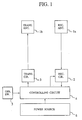
- Fig. 1 is a block diagram showing a structure of a prior art SART.
- reference numeral 1a designates an antenna for receiving radar signals (hereinafter referred to as “receiving antenna”);
- numeral 1b designates an antenna for transmitting rescue signals (hereinafter referred to as “transmitting antenna”);
- numeral 2 designates a receiving circuit to amplify and detect the radar signals received by the receiving antenna 1a;
- numeral 3 designates a transmitting circuit to generate rescue signals and output them to the transmitting antenna 1b;
- numeral 4 designates a controlling circuit to control the operation of the transmitting circuit 3 and the receiving circuit 2;
- numeral 5 designates an operating switch for operating this SART; and
- numeral 6 designates a power source to supply electric power to the receiving circuit 2, the transmitting circuit 3 and the controlling circuit 4.
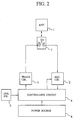
- Fig. 2 is a block diagram showing a structure of another prior art SART having an antenna for transmitting and receiving, which is commonly used as the transmitting antenna 1b and the receiving antenna 1a of Fig. 1.
- reference numeral 1 designates that antenna; and numeral 7 designates a changeover switch to change over the connection of the transmitting circuit 3 and the receiving circuit 2 to the antenna 1.
- SARTs operate in order to display their own locations on radar faceplates by receiving transmitted signals from the radars and transmitting specified rescue electric waves within receivable periods of the radars at the time of disasters. For this reason, the SARTs are begun to be used in large quantities as effective equipment, being all-weather and 24 hour type lifesaving appliances which are not influenced by the weather and time zones, for saving lives precisely and quickly.
- the SART Although the SART is in its nonoperating state usually, electric power is supplied to the receiving circuit 2, the transmitting circuit 3 and the controlling circuit 4 from the power source 6 when a sufferer turns the operating switch 5 on at the time of his or her disaster.
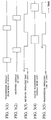
- the controlling circuit 4 brings the receiving circuit 2 on its operating state (Fig. 3(3)) at first, and it changes over the changeover switch 7 to the contact "a" of the side of the receiving circuit 2 at the same time.
- transmission signals from a radar are sent (Fig. 3(1))
- these electric waves are received by the antenna 1 of the SART after some time delays in proportion to the distance between the radar and the SART (Fig. 3(2)).
- the transmission signals received by the antenna 1 are amplified and detected at the receiving circuit 2, then they are inputted to the controlling circuit 4.
- the controlling circuit 4 changes over the changeover switch 7 to the contact "b" of the side of the transmitting circuit 3 for generating rescue signals, and it outputs transmission-beginning signals to the transmitting circuit 3 at the same time (Fig. 3(5)). Then the controlling circuit 4 causes the transmitting circuit 3 to generate rescue signals to be sent to the air from the antenna 1 (Fig. 3(4)) so as to be received by radars.
- controlling circuit 4 controls the operation timing to stop the operation of the transmitting circuit 3 during the time of receiving operation of the SART and to stop the operation of the receiving circuit 2 during the time of transmitting operation of the SART in order to prevent misoperation by interference in transmitting and receiving operation of the SART (Fig. 3(3), Fig. 3(5)).
- the SARTs are left as they are in their nonoperating states for many hours normally, as the chance of meeting a disaster is rare in spite of being made so as to operate at the time of the disaster. Consequently, it is resulted whether the SARTs operate well or not at the time of a disaster is entrusted to the reliability of the SARTs proper and their preserved conditions.
- the power sources used in the SARTs are generally primary batteries, so their terms of preservation are limited and the spans of their lives vary according to their preserved states.
- a SART comprising an operation-checking switch changing over the operation of the SART to its checking operation; and a checking function circuit outputting a timing signal to generate a rescue signal to its transmitting circuit when the operation-checking switch is turned on, the checking function circuit outputting a changeover signal to change over a changeover switch to the side of the transmitting circuit, the checking function circuit outputting another timing signal to amplify and to detect the leakage electric power of a transmission signal from the transmitting circuit which leaked at the changeover switch, the checking function circuit outputting an indicating signal to judge the propriety of the operation of the SART by comparing the output signal level of a receiving circuit with a prescribed reference level.
- the SART makes the transmitting circuit generate the transmission signal, and it makes the receiving circuit receive the transmission electric power of the transmission signal having leaked at the changeover switch at the same time, then it judges the propriety of its operation by comparing the received signal level with the reference level. Consequently, the SART can check its operation without receiving radar signals and it can ascertain easily and rapidly whether its operation is normal or not at the time other than disasters.
- a SART provided with a second changeover switch, installed between a first changeover switch and a receiving circuit, which changes over the connection of the inputting terminal of the receiving circuit between the side of the first changeover switch and the side of a non-reflecting terminating device; and a checking function circuit outputting a changeover signal to the second changeover switch when an operation-checking switch is turned on, the changeover signal changing over the second changeover switch to the non-reflecting terminating device.
- the SART inputs the leakage electric power having leaked at the second changeover switch in the leakage electric power at the first changeover switch changing over an antenna. Consequently, the SART can be checked at signal levels near to its actual operating levels by decreasing input signal levels to the receiving circuit in the case where leakage electric power from the first changeover switch to the receiving circuit is large.
- a SART provided with a coupler connected between a first changeover switch and a transmitting circuit to supply a part of the transmission electric power of the transmitting circuit to a receiving circuit, a second changeover switch connected to the coupler's receiving circuit side output terminal, and a checking function circuit outputting a changeover signal to the first and the second changeover switches when an operation-checking switch is turned on, the changeover signal changing over the first and the second changeover switches to the receiving circuit side and the coupler side respectively.
- the SART inputs a part of the transmission electric power to the receiving circuit through the coupler, and it changes over the first changeover switch to the side of the receiving circuit, and further it does not connect the second changeover switch to the side of the receiving circuit. Consequently, transmission signals are not radiated to the outside at the time of the operation-checking of the SART.
- a SART provided with a second changeover switch connected between a first changeover switch and a receiving circuit to change over the connection of an input terminal of the receiving circuit between the side of the first changeover switch and the side of a transmitting circuit; a third changeover switch connected between the first changeover switch and the transmitting circuit to change over the connection of the output terminal of the transmitting circuit between the side of the first changeover switch and the side of the receiving circuit; and a checking function circuit outputting a changeover signal to the first changeover switch, the changeover signal changing over the first changeover switch to the receiving circuit side, the checking function circuit outputting another changeover signal to the second changeover switch, the changeover signal changing over the second changeover switch to the transmitting circuit side, the checking function circuit outputting another changeover signal to the third changeover switch, the changeover signal changing over the third changeover switch to the receiving circuit side, when an operation-checking switch is turned on.
- the third changeover switch changing over the output of the transmitting circuit is changed over to the receiving circuit side, and the receiving circuit side also is apart from the antenna of the SART by the second changeover switch. Consequently, transmission signals are not radiated to the outside at the time of operation-checking of the SART.
- a SART provided with a coupler connected between a second changeover switch and a third changeover switch to supply a part of the transmission electric power of a transmitting circuit to a receiving circuit and to supply the remaining transmission electric power to a non-reflecting terminating device.
- the non-reflecting terminating device absorbs the transmission electric power. Consequently, transmission signals are not radiated to the outside.
- reference numeral 1 designates an antenna used as both transmitting one and receiving one;
- numeral 2 designates a receiving circuit to amplify and detect radar signals received by the antenna 1;
- numeral 3 designates a transmitting circuit generating rescue signals to output the antenna 1;
- numeral 4 designates a controlling circuit controlling the operation of the transmitting circuit 3 and the receiving circuit 2;
- numeral 5 designates an operating switch for operating this SART;
- numeral 6 designates a power source supplying electric power to the receiving circuit 2, the transmitting circuit 3 and the controlling circuit 4;
- numeral 7 designates a changeover switch changing over the connection of the transmitting circuit 3 and the receiving circuit 2 to the antenna 1;
- numeral 8 designates an operation-checking switch changing over the operation of the SART to the operation for checking;
- numeral 9 designates a checking function circuit in the controlling circuit 4, the checking function circuit outputting a timing signal to the transmitting circuit 3, the timing signal to generate the rescue signals, the checking function circuit outputting a changeover signal to the change
- Fig. 5 shows a internal structure of the SART.
- the controlling circuit 4 changes over the changeover switch 7 to the contact "b" of the side of the transmitting circuit 3 for generating rescue signals, and it outputs transmission-beginning signals to the transmitting circuit 3 at the same time. Then the rescue signals generated at the transmitting circuit 3 are sent to the air from the antenna 1 so as to be received by radars.
- the operation at the time of checking will be described on reference to a block diagram of Fig. 5 and a timing chart of Fig. 6.
- the operation-checking switch 8 When the operation-checking switch 8 is turned on, the voltage regulation circuit 401 is waked up and the power from the circuit 401 is provided for the checking function circuit 9. That is, the function checking signal shown in Fig. 6(1) indicates a power provided period from the voltage regulation circuit 401.
- the checking timer 1401 outputs on-signal which is active on a period of checking, for example one second, from start timing of power supply.
- An output signal of the checking timer 1401 makes the timer 402 for realizing repeats of transmitting and receiving stop, makes the switch 1403 for actuating the sweep control circuit 404 turn on and makes the switch 403 turn on to RX side.
- the transmitting circuit 3 is provided with sweep signals ( see Fig. 6(2)).
- a connection between contact "b" and contact "c" in switch 7 is achieved.
- the bias circuit 405 for actuating the receiving circuit 2 the low-frequency amplifier 406 and the comparator 407 is waked up.
- a transmission signal generated by the transmitting circuit 3 is provided for the antenna 1 through “b" and "c" contacts of the switch 7.
- Leaked electric power exists between contacts "b” and "a” on the basis of incompleteness of isolation.
- the leaked power is under about 1:1000 of the transmitting power.
- the receiving circuit 2 receives, amplifies and detects the leaked electric power of the transmission signal and the receiving circuit 2 outputs the leaked electric power to the controlling circuit 4 (Fig. 6(5).
- the controlling circuit 4 judges whether the detection level of the reception signal Vs of the receiving circuit 2 is larger than the reference level Vr or not (for example, if the reception signal Vs has a signal level Vu being larger than the reference level Vr, the SART is normal; and if the reference signal Vs has a signal level Vl being smaller than the reference level Vr, the SART is abnormal) (Fig. 6(6)), then the indicator 1404 displays the result on the displaying apparatus not shown.
- the operation-checking in this embodiment is executed by operating every component of the SART other than the antenna 1, the characteristic inferiority of every component other than the antenna 1, the deterioration of the power source and the like can be judged. Moreover, the time required to the operation-checking is momentary, and the operation-checking switch 8 will be set to turn off after a short fixed time. Accordingly, the consumption of the power source 6 accompanied by the checking operation is almost negligible.
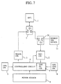
- Fig. 7 is a block diagram showing the structure of the embodiment 2 of the present invention.
- the same construction elements of the embodiment 2 as those of the embodiment of Fig. 4 are referred to as the same reference numerals, and the description of them will be omitted.
- Reference numeral 10 designates a high-frequency changeover switch, one changeover contact "b" of which is connected to the changeover contact "a" of the changeover switch 7, and the other changeover contact "a” of which is connected to a non-reflecting terminating device 11, and further the common contact of which is connected to the input contact of the receiving circuit 2.
- the detailed structure of the controlling circuit 5 is as same as in Fig. 5.
- the amount of the isolation at the changeover switch 7 varies according to the variation of the load impedance of the antenna 1, but the amount of the variation is in a degree being able to be left out of consideration on the practical use plane.
- Fig. 8 is a block diagram showing the structure of the embodiment 3 of the present invention.
- the same construction elements of the embodiment 3 as those of the embodiment of Fig. 4 are referred to as the same reference numerals, and the description of them will be omitted.
- Reference numeral 12 designates a coupler equipped between the changeover switch 7 and the transmitting circuit 3 to supply a part of the transmission electric power of the transmitting circuit 3 to the receiving circuit 2 through the changeover switch 10.
- the changeover contact "a" of the changeover switch 10 which is not connected to the coupler 12, is connected to the changeover contact "a" of the changeover switch 7.
- the detailed structure of the controlling circuit 5 is as same as in Fig. 5.
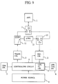
- Fig. 9 is a block diagram showing the structure of the embodiment 4 of the present invention.
- the same construction elements of the embodiment 4 as those of the embodiment of Fig. 8 are referred to as the same reference numerals, and the description of them will be omitted.
- Reference numeral 13 designates an attenuator connected between the coupler 12 and the "b" contact of the changeover switch 10.
- the output signal level of the side of the receiving circuit 2 of the coupler 12 is attenuated to the optimum level for the operation of the receiving circuit 2 by means of the attenuator 13. Accordingly, close operation-checking is possible even if the output signal level of the side of the receiving circuit 2 of the coupler 12 is large.
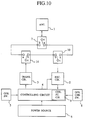
- Fig. 10 is a block diagram showing the structure of the embodiment 5 of the present invention.
- the same construction elements of the embodiment 5 as those of the embodiment of Fig. 8 are referred to as the same reference numerals, and the description of them will be omitted.
- Reference numeral 14 designates a changeover switch equipped between the changeover switch 7 and the transmitting circuit 3 to change over the connection of the output contact of the transmitting circuit 3 between the side of the changeover switch 7 and the side of the changeover switch 10. That is to say, this embodiment is provided with the changeover switch 14 instead of the coupler 12 of the embodiment of Fig. 8.
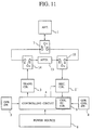
- Fig .11 is a block diagram showing the structure of the embodiment 6 of the present invention.
- the same construction elements of the embodiment 6 as those of the embodiment of Fig. 10 are referred to as the same reference numerals, and the description of them will be omitted.
- Reference numeral 13 designates an attenuator connected between the "b" contact of the changeover switch 14 and the "b" contact of the changeover switch 10.
- the output signal level of the transmitting circuit 3 is attenuated to the optimum level for the operation of the receiving circuit 2 by means of the attenuator 13. Accordingly, close operation-checking is brought to be possible even if the output signal level of the transmitting circuit 3 is large.
- Fig. 12 is a block diagram showing the structure of the embodiment 7 of the present invention.
- the same construction elements of the embodiment 7 as those of the embodiment of Fig. 10 are referred to as the same reference numerals, and the description of them will be omitted.
- Reference numeral 12 designates a coupler connected between the changeover switch 10 and the changeover switch 14 to supply a part of the transmission electric power of the transmitting circuit 3 to the receiving circuit 2 and to supply the remaining transmission electric power to the non-reflecting terminating device 11.
- a transmission signal transmitted from the transmitting circuit 3 at the time of the operation-checking of this embodiment is inputted to the coupler 12 through the changeover switch 14, and a part of the transmission signal is inputted to the receiving circuit 2 through the changeover switch 10, then the operation-checking is done.
- the other part of the transmission signal electric power is absorbed by the non-reflecting terminating device 11, so almost no signal is transmitted from the antenna 1.
- the coupling amount of the coupler 12 may be selected to be the optimum level of the operation of the receiving circuit 2.
- a SART has an operation-checking apparatus within, the operation-checking apparatus making a transmitting circuit generate a transmission signal, the operation-checking apparatus making a receiving circuit receive the transmission electric power of the transmission signal having leaked at a changeover switch at the same time, the operation-checking apparatus judging the propriety of its operation by comparing the received signal level with a reference level. Consequently, the SART has such effects that it can check its operation without receiving radar signals, and that it can ascertain easily and rapidly whether its operation is normal or not at the time other than disasters, and that it can execute effective precaution checking.
- a SART inputs leaked electric power to a receiving circuit, the leaked electric power having leaked at the second changeover switch in the leaked electric power at the first changeover switch changing over the connection of an antenna. Consequently, the SART has such an effect that it can be checked at signal levels near to its actual operating levels by decreasing input signal levels to the receiving circuit in the case where leaked electric power from the first changeover switch to the receiving circuit is large.
- a SART inputs a part of transmission electric power to a receiving circuit through a coupler, and it changes over the first changeover switch to the side of the receiving circuit, and further it does not connect the second changeover switch to the side of the receiving circuit. Consequently, such an effect can be obtained that transmission signals are not radiated to the outside at the time of the operation-checking of the SART.
- the third changeover switch changing over the output of a transmitting circuit is changed over to a receiving circuit side, and the receiving circuit side also is apart from an antenna of a SART by the second changeover switch. Consequently, such an effect can be obtained that transmission signals are not radiated to the outside at the time of operation-checking of the SART.
- a non-reflecting terminating device absorbs transmission electric power. Consequently, such an effect can be obtained that transmission signals are not radiated to the outside at the time of operation-checking of a SART.
Landscapes
- Engineering & Computer Science (AREA)
- Radar, Positioning & Navigation (AREA)
- Remote Sensing (AREA)
- Computer Networks & Wireless Communication (AREA)
- Physics & Mathematics (AREA)
- General Physics & Mathematics (AREA)
- Transmitters (AREA)
- Radar Systems Or Details Thereof (AREA)
Applications Claiming Priority (2)
| Application Number | Priority Date | Filing Date | Title |
|---|---|---|---|
| JP161741/93 | 1993-06-30 | ||
| JP5161741A JPH0755918A (ja) | 1993-06-30 | 1993-06-30 | 捜索救難用レーダ・トランスポンダ |
Publications (3)
| Publication Number | Publication Date |
|---|---|
| EP0632289A2 true EP0632289A2 (de) | 1995-01-04 |
| EP0632289A3 EP0632289A3 (de) | 1996-07-17 |
| EP0632289B1 EP0632289B1 (de) | 1999-02-24 |
Family
ID=15741007
Family Applications (1)
| Application Number | Title | Priority Date | Filing Date |
|---|---|---|---|
| EP94109339A Expired - Lifetime EP0632289B1 (de) | 1993-06-30 | 1994-06-16 | Radar-Antwortgerät für Suchen und Retten |
Country Status (5)
| Country | Link |
|---|---|
| US (1) | US5430446A (de) |
| EP (1) | EP0632289B1 (de) |
| JP (1) | JPH0755918A (de) |
| DE (1) | DE69416620T2 (de) |
| NO (1) | NO308873B1 (de) |
Cited By (1)
| Publication number | Priority date | Publication date | Assignee | Title |
|---|---|---|---|---|
| WO2005101672A1 (en) * | 2004-04-08 | 2005-10-27 | M/A-Com, Inc. | Apparatus and method for detecting radio frequency transmission power levels |
Families Citing this family (3)
| Publication number | Priority date | Publication date | Assignee | Title |
|---|---|---|---|---|
| US20090237290A1 (en) * | 2007-12-19 | 2009-09-24 | Michael Kishinevsky | Radar transponder |
| DE202010007111U1 (de) | 2010-05-21 | 2010-08-26 | Robert Bosch Gmbh | Handortungsgerätevorrichtung |
| CN103970174B (zh) * | 2014-05-19 | 2015-07-29 | 江苏万邦微电子有限公司 | 一种tr组件调试仪电源控制电路 |
Family Cites Families (12)
| Publication number | Priority date | Publication date | Assignee | Title |
|---|---|---|---|---|
| JPS5289408A (en) * | 1976-01-19 | 1977-07-27 | Mitsubishi Electric Corp | Electric wave signal device |
| NL180046C (nl) * | 1977-01-26 | 1986-12-16 | Mitsubishi Electric Corp | Radarbakeninrichting voor reddingsoperaties. |
| GB1594231A (en) * | 1977-02-12 | 1981-07-30 | Plessey Co Ltd | Transponder/interrogator systems |
| US4107675A (en) * | 1977-03-04 | 1978-08-15 | Sellers John C | Transponder-responder system |
| JPS58148526A (ja) * | 1982-02-26 | 1983-09-03 | Mitsubishi Electric Corp | 救難用信号装置 |
| US4833477A (en) * | 1987-08-12 | 1989-05-23 | Tendler Robert K | Emergency vessel location system |
| JP2561930B2 (ja) * | 1987-09-22 | 1996-12-11 | 三菱電機株式会社 | レーダー・トランスポンダ |
| JPH01131474A (ja) * | 1987-11-17 | 1989-05-24 | Mitsubishi Electric Corp | レーダ装置 |
| JPH07111459B2 (ja) * | 1988-05-12 | 1995-11-29 | 三菱電機株式会社 | レーダー・トランポンダ |
| US5153836A (en) * | 1990-08-22 | 1992-10-06 | Edward J. Fraughton | Universal dynamic navigation, surveillance, emergency location, and collision avoidance system and method |
| GB2261344A (en) * | 1991-11-08 | 1993-05-12 | Richard Morris Trim | Radar transponder |
| US5235337A (en) * | 1992-04-07 | 1993-08-10 | Acr Electronics, Inc. | Search and rescue transponder housing |
-
1993
- 1993-06-30 JP JP5161741A patent/JPH0755918A/ja active Pending
-
1994
- 1994-06-10 NO NO942180A patent/NO308873B1/no unknown
- 1994-06-13 US US08/257,905 patent/US5430446A/en not_active Expired - Fee Related
- 1994-06-16 EP EP94109339A patent/EP0632289B1/de not_active Expired - Lifetime
- 1994-06-16 DE DE69416620T patent/DE69416620T2/de not_active Expired - Fee Related
Cited By (2)
| Publication number | Priority date | Publication date | Assignee | Title |
|---|---|---|---|---|
| WO2005101672A1 (en) * | 2004-04-08 | 2005-10-27 | M/A-Com, Inc. | Apparatus and method for detecting radio frequency transmission power levels |
| US7529526B2 (en) | 2004-04-08 | 2009-05-05 | Christopher Brindle | Apparatus and method for detecting radio frequency transmission power levels |
Also Published As
| Publication number | Publication date |
|---|---|
| DE69416620T2 (de) | 1999-09-23 |
| EP0632289A3 (de) | 1996-07-17 |
| NO942180D0 (no) | 1994-06-10 |
| NO942180L (no) | 1995-01-02 |
| DE69416620D1 (de) | 1999-04-01 |
| NO308873B1 (no) | 2000-11-06 |
| JPH0755918A (ja) | 1995-03-03 |
| US5430446A (en) | 1995-07-04 |
| EP0632289B1 (de) | 1999-02-24 |
Similar Documents
| Publication | Publication Date | Title |
|---|---|---|
| US5196808A (en) | RF amplifier protector and method | |
| GB2056223A (en) | Ultra high frequency transceiver | |
| US6092027A (en) | Apparatus for detecting and recording a conduction noise, a radiation electromagnetic field noise and a discharge noise | |
| EP0632289B1 (de) | Radar-Antwortgerät für Suchen und Retten | |
| US6556815B1 (en) | Transmitting circuit in which damage to power amplifier due to reflected wave is prevented and transmitter-receiver provided with the transmitting circuit | |
| CN114089079B (zh) | 一种抗干扰测试系统 | |
| US6906663B2 (en) | E-field monitor for pulsed signals | |
| US6104287A (en) | Circulator reverse power alarm | |
| US6839781B1 (en) | Wireless keyboard and information processing device having the same | |
| US4682174A (en) | Moving target indicator using a surface acoustic wave device | |
| AU2023245304B2 (en) | Radio frequency detector for test chamber | |
| CN211375059U (zh) | 一种带自检功能的超声波测深仪 | |
| JP2955381B2 (ja) | レーダ装置 | |
| KR20050051780A (ko) | 단말기 안테나 진단 장치 및 방법 | |
| KR19980036999A (ko) | 선배열 음파탐지기의 배열 모듈 전원부 검사 장치 | |
| KR100396293B1 (ko) | 마이크로 프로세서를 이용한 누전 경보 기능을 가지는누전 계전기 | |
| JP2841998B2 (ja) | 送受信機検査装置 | |
| KR100222402B1 (ko) | 티디엠에이 방식의 디지털 이동통신 장치에서 송신 출력레벨 검출장치 | |
| JPH06296168A (ja) | 無線送信装置 | |
| JP2001148671A (ja) | 空中線異常検出装置 | |
| JPH05172879A (ja) | アンテナおよびアンテナ給電系の監視装置 | |
| KR100499110B1 (ko) | 레이더 송수신 튜브 검사장치 및 방법 | |
| JP2000039460A (ja) | 無線装置の評価方法 | |
| JPH06222133A (ja) | 2次レーダおよび2次レーダ異常検出方法 | |
| JPH1155157A (ja) | 空中線共用器 |
Legal Events
| Date | Code | Title | Description |
|---|---|---|---|
| PUAI | Public reference made under article 153(3) epc to a published international application that has entered the european phase |
Free format text: ORIGINAL CODE: 0009012 |
|
| AK | Designated contracting states |
Kind code of ref document: A2 Designated state(s): DE FR GB |
|
| PUAL | Search report despatched |
Free format text: ORIGINAL CODE: 0009013 |
|
| AK | Designated contracting states |
Kind code of ref document: A3 Designated state(s): DE FR GB |
|
| 17P | Request for examination filed |
Effective date: 19960916 |
|
| GRAG | Despatch of communication of intention to grant |
Free format text: ORIGINAL CODE: EPIDOS AGRA |
|
| 17Q | First examination report despatched |
Effective date: 19980519 |
|
| GRAG | Despatch of communication of intention to grant |
Free format text: ORIGINAL CODE: EPIDOS AGRA |
|
| GRAH | Despatch of communication of intention to grant a patent |
Free format text: ORIGINAL CODE: EPIDOS IGRA |
|
| GRAH | Despatch of communication of intention to grant a patent |
Free format text: ORIGINAL CODE: EPIDOS IGRA |
|
| GRAA | (expected) grant |
Free format text: ORIGINAL CODE: 0009210 |
|
| AK | Designated contracting states |
Kind code of ref document: B1 Designated state(s): DE FR GB |
|
| REF | Corresponds to: |
Ref document number: 69416620 Country of ref document: DE Date of ref document: 19990401 |
|
| ET | Fr: translation filed | ||
| REG | Reference to a national code |
Ref country code: GB Ref legal event code: 727 |
|
| REG | Reference to a national code |
Ref country code: GB Ref legal event code: 727A |
|
| REG | Reference to a national code |
Ref country code: GB Ref legal event code: 727B |
|
| REG | Reference to a national code |
Ref country code: GB Ref legal event code: SP |
|
| PLBE | No opposition filed within time limit |
Free format text: ORIGINAL CODE: 0009261 |
|
| STAA | Information on the status of an ep patent application or granted ep patent |
Free format text: STATUS: NO OPPOSITION FILED WITHIN TIME LIMIT |
|
| 26N | No opposition filed | ||
| REG | Reference to a national code |
Ref country code: GB Ref legal event code: IF02 |
|
| PGFP | Annual fee paid to national office [announced via postgrant information from national office to epo] |
Ref country code: FR Payment date: 20050608 Year of fee payment: 12 |
|
| PGFP | Annual fee paid to national office [announced via postgrant information from national office to epo] |
Ref country code: DE Payment date: 20050609 Year of fee payment: 12 |
|
| PGFP | Annual fee paid to national office [announced via postgrant information from national office to epo] |
Ref country code: GB Payment date: 20050615 Year of fee payment: 12 |
|
| PG25 | Lapsed in a contracting state [announced via postgrant information from national office to epo] |
Ref country code: GB Free format text: LAPSE BECAUSE OF NON-PAYMENT OF DUE FEES Effective date: 20060616 |
|
| PG25 | Lapsed in a contracting state [announced via postgrant information from national office to epo] |
Ref country code: DE Free format text: LAPSE BECAUSE OF NON-PAYMENT OF DUE FEES Effective date: 20070103 |
|
| GBPC | Gb: european patent ceased through non-payment of renewal fee |
Effective date: 20060616 |
|
| REG | Reference to a national code |
Ref country code: FR Ref legal event code: ST Effective date: 20070228 |
|
| PG25 | Lapsed in a contracting state [announced via postgrant information from national office to epo] |
Ref country code: FR Free format text: LAPSE BECAUSE OF NON-PAYMENT OF DUE FEES Effective date: 20060630 |