EP0629783B1 - Kombinierte Steuerung von Pneumatik- und Hydraulikventilen - Google Patents
Kombinierte Steuerung von Pneumatik- und Hydraulikventilen Download PDFInfo
- Publication number
- EP0629783B1 EP0629783B1 EP94103405A EP94103405A EP0629783B1 EP 0629783 B1 EP0629783 B1 EP 0629783B1 EP 94103405 A EP94103405 A EP 94103405A EP 94103405 A EP94103405 A EP 94103405A EP 0629783 B1 EP0629783 B1 EP 0629783B1
- Authority
- EP
- European Patent Office
- Prior art keywords
- valve
- control
- valve station
- valves
- station according
- Prior art date
- Legal status (The legal status is an assumption and is not a legal conclusion. Google has not performed a legal analysis and makes no representation as to the accuracy of the status listed.)
- Expired - Lifetime
Links
Images
Classifications
-
- F—MECHANICAL ENGINEERING; LIGHTING; HEATING; WEAPONS; BLASTING
- F15—FLUID-PRESSURE ACTUATORS; HYDRAULICS OR PNEUMATICS IN GENERAL
- F15B—SYSTEMS ACTING BY MEANS OF FLUIDS IN GENERAL; FLUID-PRESSURE ACTUATORS, e.g. SERVOMOTORS; DETAILS OF FLUID-PRESSURE SYSTEMS, NOT OTHERWISE PROVIDED FOR
- F15B13/00—Details of servomotor systems ; Valves for servomotor systems
- F15B13/02—Fluid distribution or supply devices characterised by their adaptation to the control of servomotors
- F15B13/06—Fluid distribution or supply devices characterised by their adaptation to the control of servomotors for use with two or more servomotors
- F15B13/08—Assemblies of units, each for the control of a single servomotor only
- F15B13/0803—Modular units
- F15B13/0846—Electrical details
- F15B13/0857—Electrical connecting means, e.g. plugs, sockets
-
- F—MECHANICAL ENGINEERING; LIGHTING; HEATING; WEAPONS; BLASTING
- F15—FLUID-PRESSURE ACTUATORS; HYDRAULICS OR PNEUMATICS IN GENERAL
- F15B—SYSTEMS ACTING BY MEANS OF FLUIDS IN GENERAL; FLUID-PRESSURE ACTUATORS, e.g. SERVOMOTORS; DETAILS OF FLUID-PRESSURE SYSTEMS, NOT OTHERWISE PROVIDED FOR
- F15B13/00—Details of servomotor systems ; Valves for servomotor systems
- F15B13/02—Fluid distribution or supply devices characterised by their adaptation to the control of servomotors
- F15B13/06—Fluid distribution or supply devices characterised by their adaptation to the control of servomotors for use with two or more servomotors
- F15B13/08—Assemblies of units, each for the control of a single servomotor only
- F15B13/0803—Modular units
- F15B13/0807—Manifolds
- F15B13/0814—Monoblock manifolds
-
- F—MECHANICAL ENGINEERING; LIGHTING; HEATING; WEAPONS; BLASTING
- F15—FLUID-PRESSURE ACTUATORS; HYDRAULICS OR PNEUMATICS IN GENERAL
- F15B—SYSTEMS ACTING BY MEANS OF FLUIDS IN GENERAL; FLUID-PRESSURE ACTUATORS, e.g. SERVOMOTORS; DETAILS OF FLUID-PRESSURE SYSTEMS, NOT OTHERWISE PROVIDED FOR
- F15B13/00—Details of servomotor systems ; Valves for servomotor systems
- F15B13/02—Fluid distribution or supply devices characterised by their adaptation to the control of servomotors
- F15B13/06—Fluid distribution or supply devices characterised by their adaptation to the control of servomotors for use with two or more servomotors
- F15B13/08—Assemblies of units, each for the control of a single servomotor only
- F15B13/0803—Modular units
- F15B13/0846—Electrical details
- F15B13/086—Sensing means, e.g. pressure sensors
-
- F—MECHANICAL ENGINEERING; LIGHTING; HEATING; WEAPONS; BLASTING
- F15—FLUID-PRESSURE ACTUATORS; HYDRAULICS OR PNEUMATICS IN GENERAL
- F15B—SYSTEMS ACTING BY MEANS OF FLUIDS IN GENERAL; FLUID-PRESSURE ACTUATORS, e.g. SERVOMOTORS; DETAILS OF FLUID-PRESSURE SYSTEMS, NOT OTHERWISE PROVIDED FOR
- F15B13/00—Details of servomotor systems ; Valves for servomotor systems
- F15B13/02—Fluid distribution or supply devices characterised by their adaptation to the control of servomotors
- F15B13/06—Fluid distribution or supply devices characterised by their adaptation to the control of servomotors for use with two or more servomotors
- F15B13/08—Assemblies of units, each for the control of a single servomotor only
- F15B13/0803—Modular units
- F15B13/0846—Electrical details
- F15B13/0867—Data bus systems
-
- F—MECHANICAL ENGINEERING; LIGHTING; HEATING; WEAPONS; BLASTING
- F15—FLUID-PRESSURE ACTUATORS; HYDRAULICS OR PNEUMATICS IN GENERAL
- F15B—SYSTEMS ACTING BY MEANS OF FLUIDS IN GENERAL; FLUID-PRESSURE ACTUATORS, e.g. SERVOMOTORS; DETAILS OF FLUID-PRESSURE SYSTEMS, NOT OTHERWISE PROVIDED FOR
- F15B13/00—Details of servomotor systems ; Valves for servomotor systems
- F15B13/02—Fluid distribution or supply devices characterised by their adaptation to the control of servomotors
- F15B13/06—Fluid distribution or supply devices characterised by their adaptation to the control of servomotors for use with two or more servomotors
- F15B13/08—Assemblies of units, each for the control of a single servomotor only
- F15B13/0803—Modular units
- F15B13/0875—Channels for electrical components, e.g. for cables or sensors
-
- F—MECHANICAL ENGINEERING; LIGHTING; HEATING; WEAPONS; BLASTING
- F15—FLUID-PRESSURE ACTUATORS; HYDRAULICS OR PNEUMATICS IN GENERAL
- F15B—SYSTEMS ACTING BY MEANS OF FLUIDS IN GENERAL; FLUID-PRESSURE ACTUATORS, e.g. SERVOMOTORS; DETAILS OF FLUID-PRESSURE SYSTEMS, NOT OTHERWISE PROVIDED FOR
- F15B13/00—Details of servomotor systems ; Valves for servomotor systems
- F15B13/02—Fluid distribution or supply devices characterised by their adaptation to the control of servomotors
- F15B13/06—Fluid distribution or supply devices characterised by their adaptation to the control of servomotors for use with two or more servomotors
- F15B13/08—Assemblies of units, each for the control of a single servomotor only
- F15B13/0803—Modular units
- F15B13/0878—Assembly of modular units
- F15B13/0885—Assembly of modular units using valves combined with other components
- F15B13/0889—Valves combined with electrical components
-
- F—MECHANICAL ENGINEERING; LIGHTING; HEATING; WEAPONS; BLASTING
- F15—FLUID-PRESSURE ACTUATORS; HYDRAULICS OR PNEUMATICS IN GENERAL
- F15B—SYSTEMS ACTING BY MEANS OF FLUIDS IN GENERAL; FLUID-PRESSURE ACTUATORS, e.g. SERVOMOTORS; DETAILS OF FLUID-PRESSURE SYSTEMS, NOT OTHERWISE PROVIDED FOR
- F15B21/00—Common features of fluid actuator systems; Fluid-pressure actuator systems or details thereof, not covered by any other group of this subclass
- F15B21/08—Servomotor systems incorporating electrically operated control means
- F15B21/085—Servomotor systems incorporating electrically operated control means using a data bus, e.g. "CANBUS"
-
- Y—GENERAL TAGGING OF NEW TECHNOLOGICAL DEVELOPMENTS; GENERAL TAGGING OF CROSS-SECTIONAL TECHNOLOGIES SPANNING OVER SEVERAL SECTIONS OF THE IPC; TECHNICAL SUBJECTS COVERED BY FORMER USPC CROSS-REFERENCE ART COLLECTIONS [XRACs] AND DIGESTS
- Y10—TECHNICAL SUBJECTS COVERED BY FORMER USPC
- Y10T—TECHNICAL SUBJECTS COVERED BY FORMER US CLASSIFICATION
- Y10T137/00—Fluid handling
- Y10T137/7722—Line condition change responsive valves
- Y10T137/7837—Direct response valves [i.e., check valve type]
- Y10T137/7879—Resilient material valve
- Y10T137/788—Having expansible port
-
- Y—GENERAL TAGGING OF NEW TECHNOLOGICAL DEVELOPMENTS; GENERAL TAGGING OF CROSS-SECTIONAL TECHNOLOGIES SPANNING OVER SEVERAL SECTIONS OF THE IPC; TECHNICAL SUBJECTS COVERED BY FORMER USPC CROSS-REFERENCE ART COLLECTIONS [XRACs] AND DIGESTS
- Y10—TECHNICAL SUBJECTS COVERED BY FORMER USPC
- Y10T—TECHNICAL SUBJECTS COVERED BY FORMER US CLASSIFICATION
- Y10T137/00—Fluid handling
- Y10T137/8593—Systems
- Y10T137/87169—Supply and exhaust
- Y10T137/87217—Motor
Definitions
- the invention relates to a valve station for use in connection with the control of fluid-actuated devices, for example working cylinders, with a fluid distributor having internal fluid channels, which is equipped with electrically actuated pneumatic valves that communicate with the fluid channels, and with a signal distributor, from which the Pneumatic valves receive their electrical actuation signals.
- Valve stations of this type which are also referred to as valve terminals, can be found, for example, in DE-U-92 11 109. They have a plate-like fluid distributor, inside which there are fluid channels that communicate with the pneumatic valves arranged on it.
- a signal distributor for example designed as a control unit, is in electrical connection with the valve actuators of the pneumatic valves and supplies the necessary electrical actuation signals. In this way, the valves can be switched as required in order to control connected fluid-operated devices with regard to their mode of operation.
- Such a valve station allows the actuation of fluid-operated devices from a central location. This facilitates both the set-up and later operation, including monitoring of machines and systems that are equipped with fluid-operated devices. If these fluid-actuated devices are not only pneumatically actuated but also hydraulically actuated devices, so far, however, a completely separate control has been carried out, since in hydraulic operation different parameters come into play than in pneumatics. The constructional effort is therefore enormous, especially with regard to the electrical and electronics that are required to control the different types of valves.
- the object of the present invention is to reduce the structural outlay incurred in connection with the parallel operation of pneumatic and hydraulic valves.
- valve station is designed for combined control of both pneumatic valves and hydraulic valves, and has at least one control connection for connection to at least one electrically actuable valve drive of a hydraulic valve.
- Such a valve station is also known from DE-A-39 10 913 which is suitable for equipping with both hydraulic and pneumatic valves. However, a combination of the two types of valves is not intended.
- both pneumatic valves and hydraulic valves can be controlled and actuated via a single valve station, which allows an optimal function linkage. It is possible to control both types of valve via a common control unit, which is particularly advantageous if the control unit is formed by the signal distributor of the valve station and forms a direct part of the same. It has been recognized that pneumatics and hydraulics can be linked in this way without mutual interference, which, above all, considerably simplifies the installation work and the operation of complex systems or machines.
- control connections would be conceivable, in particular, connecting devices which are installed in or on the fluid distributor and with which the valve drives of the hydraulic valves can be automatically coupled when the assigned fluid distributor is equipped.
- control connections for the hydraulic valves as connections for at least one signal conductor, via which external hydraulic valves can be connected, that is, hydraulic valves that do not form a direct part of the valve station.
- valve station In the case of the control of external hydraulic valves, it is expedient to provide the assigned control connections in at least one control part of the valve station, which can be integrated in the signal distributor, but is expediently a separate component or module which forms a fixed, possibly detachable part of the valve station . If several such control parts are provided, the valve station can be constructed as required; one could speak of a modular valve station.
- valve station can also have further outputs and / or inputs for control signals, which in particular are also provided on at least one control part.
- Signal conductors can be connected to them, in particular to Monitoring devices such as sensors or the like. to lead.
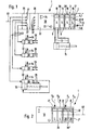
- the valve station 1 shown in FIG. 1 contains a fluid distributor 2 for pneumatic pressure medium.
- a plurality of pneumatic valves 4, which are multi-way valves, are detachably arranged on an assembly surface 3 of the fluid distributor 2.
- the valve channels of the pneumatic valves 4, not shown in any more detail, communicate with internal fluid channels 5, that is to say inside the fluid distributor 2, which are only partially indicated by dashed lines.
- One of these fluid channels 5 is expedient a feed channel 6, which can be connected to a pressure medium source P via a connection opening 13 and which, on the other hand, opens out in the region of each valve 4 to the mounting surface 3.
- a fluid channel 5 serving as an exhaust air duct 7 has a corresponding course, to the central outlet opening 14 of which a muffler or an exhaust air duct which holds the exhaust air can be connected.
- Each pneumatic valve 4 communicates both with the feed channel 6 and with the exhaust air channel 7 via the openings on the assembly surface 3. Furthermore, each pneumatic valve 4 communicates with at least one and in particular two consumer channels 8 of the fluid distributor 2, which open on the outside of the fluid distributor 2, so that pressure medium lines 12 can be connected, which lead to pneumatically actuated devices 15. In the exemplary embodiment, for the sake of simplicity, only such a device 15, which is a working cylinder, is shown schematically.
- connected pneumatically actuated devices can be supplied with compressed air or vented.
- the pneumatic valves 4 are actuated electrically. They each contain an electrically actuable valve drive 16, which regularly contains at least one electromagnet, and which is preferably a so-called solenoid valve. Each valve drive 16 is in electrical connection with an electrical conductor arrangement 17, which extends along the fluid distributor 2, in particular within the fluid distributor 2 in a suitable channel. For the connection to the valve drives 16, electrical plug-in means are expediently provided, so that the electrical connection is established automatically during valve assembly.
- the electrical conductor arrangement 17 is based on a signal distributor 18 which is arranged on an end face of the fluid distributor 2 and in particular is permanently attached.
- the signal distributor 18 is formed by a control unit 22 which contains a control program and in particular is freely programmable, so that autonomous operation is possible.
- An interface 23 enables the connection of a computer (PC) for programming and setup purposes.
- Further interfaces 24 form outputs and / or inputs of a field bus, via the further signal distributors of other valve stations can be connected.
- a signal distributor 18 a fieldbus communication unit without its own control program, which communicates with an external control unit and receives the corresponding signals from the latter, on the basis of which the actuation signals are distributed to the pneumatic valves 4.
- a fieldbus solution conventional 1: 1 wiring would also be possible, in particular using so-called multipole lines.
- the signal distributor could be a simple bus that drives the valve drives.
- control part 25, 26 which communicate with the control unit 22 of the valve station via electrical conductors, not shown, by connecting them to the signal distributor 18, for example.
- the corresponding electrical conductors are not shown in the drawing, since they run inside the control parts 25, 26.
- Each control part 25, 26 expediently contains a conductor section which is continuous in the direction of attachment, the conductor sections complementing one another in the assembled state to form a continuous conductor strand.
- control connections are on one of the control parts 25 27 provided, which are accessible from the outside. They are designed so that they can be used to control hydraulic valves 28 to which electrically actuable valve drives 32 are assigned.
- Each control connection 27 represents a control signal output which is in electrical connection with the individual valve drives 32 via one or more signal conductors 33.
- the signal conductors 33 can be wires or cables that can be laid easily and flexibly, so that the hydraulic valves 28 with their valve drives 32 can be installed practically any distance from the valve terminal 1.
- the valve drives 32 receive the control signals required for actuation, which are caused by the control unit 22, via the signal conductors 33 and the control connections 27.
- each control connection 27 an electrical and / or electronic output stage which is adapted to the valve drive to be controlled and which processes the electrical actuation signals coming from the control unit 22 in such a way that they act as direct actuation signals for the valve drives 32 of the hydraulic valves 28 can be used.
- control connections of the control part 25 are preferably designed as electrical plug connections, so that the signal conductors 33 can be connected or disconnected quickly.
- the valve station 1 of the exemplary embodiment is designed to control or actuate four hydraulic valves 28, which is why the relevant control part 25 has four control signal outputs or control connections 27. It goes without saying that a different number of control connections 27 can also be provided, for example only one.
- Each hydraulic valve 28 communicates with a system of hydraulic lines, indicated by arrows 34, which establish the connection to a supply source and a tank.
- a common line system 34 can be provided for all hydraulic valves 28.
- the hydraulic valves 28 are connected via consumer lines, which are indicated by further arrows 35, connected to the hydraulically operated devices, only such a device 36 is shown in simplified form, which is a hydraulic working cylinder. It can be seen that the hydraulic valves 28 can be attached directly to the device 36 to be actuated.
- the control part 25 forms a module of the valve station 1.
- the valve station 1 can be constructed in a modular manner to the desired extent.
- further control parts 25 can therefore be provided, which have control signal outputs for control connections 27 forming hydraulic valves.
- at least one further control part 26 which is provided with outputs and / or inputs 37, via which signals can be transmitted to and / or from other devices which are required for the operation of the valve station or from the latter be operated.
- outputs and / or inputs 37 enable the connection of monitoring devices such as sensors or the like, on the basis of whose signals the control unit 22 carries out the distribution of the electrical actuation signals.
- a control part 25 is provided exclusively for the control of hydraulic valves 28, while a control part 26 is provided exclusively with outputs and / or inputs 37 for monitoring devices.
- a single control part can contain a mixture of inputs and outputs or control connections of various types.
- valve station 1 which is suitable for the combined actuation of both pneumatic valves 4 and hydraulic valves 28.
- a common control unit 22 is sufficient to control both types of valve, which results in a relatively low construction effort, particularly with regard to the electronics side. It is possible to precisely coordinate the actuation of the pneumatic valves and the hydraulic valves, an actuation which is independent of one another being able to be implemented. Due to the modular structure of the valve station, it is also possible to operate it with only one of the two valve types if necessary. One could omit the control block 25 and would have a valve station equipped and working exclusively with pneumatic valves. It would also be possible to omit the fluid distributor 2 with all pneumatic valves 4 and the remaining part of the valve station exclusively for actuation and actuation of hydraulic valves 28 to use.
- the fluid distributor 2 as such also be of modular construction, which is the case in the exemplary embodiment.
- the fluid distributor 2 is subdivided into a plurality of length sections which form adjoining distributor modules 38, each of which is equipped with at least one pneumatic valve 4.
- the pneumatic part can thus be expanded practically as desired.
- valve assembly 2 schematically shows the possibility of arranging both pneumatic valves 4 and hydraulic valves 28 directly on a fluid distributor 2 'of the valve station 1.
- the electrical conductor arrangement 17 emanating from the signal distributor 18 serves for the simultaneous supply of both valve types with the necessary electrical actuation signals.
- the control connections 27 are provided here in the area of the assembly locations for the hydraulic valves 28 and are connected to the electrical conductor arrangement 17, the electrical valve drives 32 of the hydraulic valves 28 advantageously being automatically connected to the control connections during valve assembly 27 can be connected.
- one can also provide a separate electrical conductor arrangement for the hydraulic valves 28 (not shown), which, however, expediently extends parallel to that for the pneumatic valves 4.
- the fluid distributor 2 'contains two mutually independent channel systems for the two types of valves, which is indicated in FIG. 2 by arrows P p / R p and P h / R h . Both channel systems can run according to the internal channel profile in the fluid distributor 2 of the embodiment according to FIG. 1. However, it is advantageous here if the fluid distributor 2 has its own distributor module 39, 39 'for each valve type, each of which has its own channel system. In the exemplary embodiment, two such distribution modules 39, 39 'are provided, one (39) of which is equipped with a pneumatic and the other (39') with a hydraulic channel system. A fluidic connection between distributor modules 39, 39 'of different types is not necessary in this case, but the electrical series connection is expediently retained. The distributor modules 39, 39 'can be subdivided even more modularly.
- valve station 1 can also have control parts 25, 26 (not shown in more detail), via which a signal connection to external devices takes place. You can combine the possibilities of setting up a valve station shown using the two exemplary embodiments.
- both the control parts 25, 26 and the distribution modules 38; 39, 39 'in a linear mounting direction 40 can be successively attached to one another, the control parts 25, 26 on the one hand and the distributor modules 38; 39, 39 'are expediently attached to opposite sides of the signal distributor 18, which itself expediently has a block-like structure.
Landscapes
- Engineering & Computer Science (AREA)
- Physics & Mathematics (AREA)
- Fluid Mechanics (AREA)
- Mechanical Engineering (AREA)
- General Engineering & Computer Science (AREA)
- Chemical & Material Sciences (AREA)
- Analytical Chemistry (AREA)
- Fluid-Pressure Circuits (AREA)
- Servomotors (AREA)
- Valve Housings (AREA)
- Valve Device For Special Equipments (AREA)
Applications Claiming Priority (2)
| Application Number | Priority Date | Filing Date | Title |
|---|---|---|---|
| DE4312729A DE4312729A1 (de) | 1993-04-20 | 1993-04-20 | Ventilstation |
| DE4312729 | 1993-04-20 |
Publications (2)
| Publication Number | Publication Date |
|---|---|
| EP0629783A1 EP0629783A1 (de) | 1994-12-21 |
| EP0629783B1 true EP0629783B1 (de) | 1997-10-08 |
Family
ID=6485814
Family Applications (1)
| Application Number | Title | Priority Date | Filing Date |
|---|---|---|---|
| EP94103405A Expired - Lifetime EP0629783B1 (de) | 1993-04-20 | 1994-03-07 | Kombinierte Steuerung von Pneumatik- und Hydraulikventilen |
Country Status (6)
| Country | Link |
|---|---|
| US (1) | US5490385A (es) |
| EP (1) | EP0629783B1 (es) |
| KR (1) | KR0157094B1 (es) |
| AT (1) | ATE159082T1 (es) |
| DE (2) | DE4312729A1 (es) |
| ES (1) | ES2108315T3 (es) |
Cited By (2)
| Publication number | Priority date | Publication date | Assignee | Title |
|---|---|---|---|---|
| EP1180602A1 (de) | 2000-08-08 | 2002-02-20 | Festo AG & Co | Steuerventileinrichtung sowie als Bestandteil derselben geeignetes Ventil |
| US6468092B1 (en) | 1999-12-10 | 2002-10-22 | Festo Ag & Co. | Electronic component, in a particular for a control device provided with valves |
Families Citing this family (9)
| Publication number | Priority date | Publication date | Assignee | Title |
|---|---|---|---|---|
| DE4444024A1 (de) * | 1994-12-10 | 1996-06-13 | Festo Kg | Steuereinrichtung, insbesondere zur Ansteuerung von Ventilen |
| EP0803653B1 (de) * | 1996-04-26 | 2000-08-02 | Hygrama Ag | Pneumatische Betätigungsanordnung |
| JP3399878B2 (ja) * | 1999-07-16 | 2003-04-21 | エスエムシー株式会社 | リレー装置付きマニホールド形電磁弁 |
| DE10115913B4 (de) * | 2001-03-30 | 2004-12-09 | Festo Ag & Co. | Ventilanordnung |
| EP1515050B1 (de) * | 2003-04-01 | 2006-06-14 | FESTO AG & Co | Steuergerät |
| DE102004011638A1 (de) * | 2004-03-10 | 2005-09-29 | Ina-Schaeffler Kg | Elektrohydraulisches Schaltmodul |
| US7293494B2 (en) * | 2004-12-23 | 2007-11-13 | Caterpillar Inc. | Expandable hydraulic valve stack |
| US8862337B2 (en) | 2010-07-28 | 2014-10-14 | Illinois Tool Works Inc. | Hydraulic tool control that switches output |
| DE102016120029A1 (de) * | 2016-10-20 | 2018-04-26 | Bürkert Werke GmbH | Ventilanordnung |
Family Cites Families (12)
| Publication number | Priority date | Publication date | Assignee | Title |
|---|---|---|---|---|
| US3111139A (en) * | 1961-09-29 | 1963-11-19 | Beckett Harcum Co | Stack type valves |
| US3503414A (en) * | 1967-12-20 | 1970-03-31 | Hydrel Ag | Plug-in valve for hydraulic and pneumatic control systems |
| US3959883A (en) * | 1973-07-23 | 1976-06-01 | Walls Earl L | Hand control system for power hand tools |
| ES449780A1 (es) * | 1975-07-14 | 1977-08-16 | B & G Hydraulics Ltd | Aparato para representar las conexiones entre una pluralidadde componentes de circuito. |
| DE2752938C2 (de) * | 1977-11-26 | 1985-06-20 | Bürkert GmbH, 7118 Ingelfingen | Steuerventilanordnung für zahnärztliche Geräte |
| SU1059285A1 (ru) * | 1982-04-22 | 1983-12-07 | Гомельское Головное Специальное Конструкторско-Технологическое Бюро Гидроаппаратуры С Опытно-Экспериментальным Производством | Устройство дл монтажа гидро-и пневмоаппаратуры |
| DE3302253A1 (de) * | 1983-01-24 | 1984-07-26 | Göncöl, Eva, St. Gallen | Fluidischer baustein |
| JPH01203780A (ja) * | 1988-02-09 | 1989-08-16 | Tsubakimoto Chain Co | マニホールドバルブ |
| DE3827749A1 (de) * | 1988-08-16 | 1990-02-22 | Festo Kg | Aufspannvorrichtung |
| DE3834815C2 (de) * | 1988-10-13 | 1996-08-29 | Staiger Steuerungstech | Steuervorrichtung |
| DE3910913C2 (de) * | 1989-04-05 | 1997-02-27 | Festo Kg | Pneumatische oder hydraulische Ventileinheit |
| US5234033A (en) * | 1989-04-05 | 1993-08-10 | Festo Kg | Fluid power valve unit |
-
1993
- 1993-04-20 DE DE4312729A patent/DE4312729A1/de not_active Withdrawn
-
1994
- 1994-03-07 ES ES94103405T patent/ES2108315T3/es not_active Expired - Lifetime
- 1994-03-07 DE DE59404248T patent/DE59404248D1/de not_active Expired - Fee Related
- 1994-03-07 EP EP94103405A patent/EP0629783B1/de not_active Expired - Lifetime
- 1994-03-07 AT AT94103405T patent/ATE159082T1/de not_active IP Right Cessation
- 1994-03-25 US US08/218,121 patent/US5490385A/en not_active Expired - Fee Related
- 1994-04-15 KR KR1019940007899A patent/KR0157094B1/ko not_active IP Right Cessation
Cited By (3)
| Publication number | Priority date | Publication date | Assignee | Title |
|---|---|---|---|---|
| US6468092B1 (en) | 1999-12-10 | 2002-10-22 | Festo Ag & Co. | Electronic component, in a particular for a control device provided with valves |
| EP1180602A1 (de) | 2000-08-08 | 2002-02-20 | Festo AG & Co | Steuerventileinrichtung sowie als Bestandteil derselben geeignetes Ventil |
| US6681800B2 (en) | 2000-08-08 | 2004-01-27 | Festo Ag & Co. | Control valve means and furthermore a valve suitable for use as a component thereof |
Also Published As
| Publication number | Publication date |
|---|---|
| EP0629783A1 (de) | 1994-12-21 |
| ATE159082T1 (de) | 1997-10-15 |
| KR0157094B1 (ko) | 1999-02-18 |
| DE4312729A1 (de) | 1994-10-27 |
| ES2108315T3 (es) | 1997-12-16 |
| US5490385A (en) | 1996-02-13 |
| DE59404248D1 (de) | 1997-11-13 |
Similar Documents
| Publication | Publication Date | Title |
|---|---|---|
| EP0608245B1 (de) | Elektro-pneumatische steuereinrichtung | |
| EP1013940B1 (de) | Ventilanordnung | |
| DE60301746T2 (de) | Pneumatikventilgruppe mit einfacher Installierung und einfacher Wartung | |
| DE4004834C2 (de) | Ventilbaugruppe | |
| DE60016655T2 (de) | Magnetventilverteilplatte, angetrieben durch seriellen Signale | |
| DE4230414C2 (de) | Elektro-pneumatische Steuereinrichtung | |
| EP1710447B1 (de) | Elektrofluidisches Steuergerät | |
| EP1174781B1 (de) | Einrichtung zur Signalübertragung | |
| EP0629783B1 (de) | Kombinierte Steuerung von Pneumatik- und Hydraulikventilen | |
| EP2031542A1 (de) | Ventileinheit mit elektronischen Ventilerkennungsmitteln | |
| WO1998041766A1 (de) | Plattenartige montagebasis | |
| DE3427589C2 (es) | ||
| DE4444024A1 (de) | Steuereinrichtung, insbesondere zur Ansteuerung von Ventilen | |
| EP1041325B1 (de) | Ventileinheit | |
| EP0621407B1 (de) | Ventilstation | |
| EP3296602B1 (de) | Fluidverteilervorrichtung | |
| DE102015221259A1 (de) | Ventilmodul und Ventilanordnung | |
| EP1180602B1 (de) | Steuerventileinrichtung sowie als Bestandteil derselben geeignetes Ventil | |
| DE10203792B4 (de) | Pneumatische Ventileinheit mit einer parallelen elektrischen Verdrahtung | |
| EP0930130B1 (de) | Spannvorrichtung | |
| EP0624831B1 (de) | Steuereinrichtung zur Verwendung im Zusammenhang mit fluidbetätigbaren Einrichtungen | |
| EP1284371B1 (de) | Matrixartige Ventilanordnung | |
| EP1251283B1 (de) | Baukasten zur Herstellung eines fluidtechnischen Steuergerätes | |
| DE10213397A1 (de) | Ventilanordnung | |
| EP1205256B1 (de) | Farbwechselventilanordnung und Verfahren zu ihrer Steuerung |
Legal Events
| Date | Code | Title | Description |
|---|---|---|---|
| PUAI | Public reference made under article 153(3) epc to a published international application that has entered the european phase |
Free format text: ORIGINAL CODE: 0009012 |
|
| AK | Designated contracting states |
Kind code of ref document: A1 Designated state(s): AT CH DE ES FR IT LI NL |
|
| 17P | Request for examination filed |
Effective date: 19941115 |
|
| GRAG | Despatch of communication of intention to grant |
Free format text: ORIGINAL CODE: EPIDOS AGRA |
|
| GRAG | Despatch of communication of intention to grant |
Free format text: ORIGINAL CODE: EPIDOS AGRA |
|
| 17Q | First examination report despatched |
Effective date: 19970124 |
|
| GRAH | Despatch of communication of intention to grant a patent |
Free format text: ORIGINAL CODE: EPIDOS IGRA |
|
| GRAH | Despatch of communication of intention to grant a patent |
Free format text: ORIGINAL CODE: EPIDOS IGRA |
|
| GRAA | (expected) grant |
Free format text: ORIGINAL CODE: 0009210 |
|
| AK | Designated contracting states |
Kind code of ref document: B1 Designated state(s): AT CH DE ES FR IT LI NL |
|
| REF | Corresponds to: |
Ref document number: 159082 Country of ref document: AT Date of ref document: 19971015 Kind code of ref document: T |
|
| REG | Reference to a national code |
Ref country code: CH Ref legal event code: NV Representative=s name: TROESCH SCHEIDEGGER WERNER AG Ref country code: CH Ref legal event code: EP |
|
| ITF | It: translation for a ep patent filed |
Owner name: CON LOR S.R.L. |
|
| RAP2 | Party data changed (patent owner data changed or rights of a patent transferred) |
Owner name: FESTO AG & CO |
|
| REF | Corresponds to: |
Ref document number: 59404248 Country of ref document: DE Date of ref document: 19971113 |
|
| REG | Reference to a national code |
Ref country code: ES Ref legal event code: FG2A Ref document number: 2108315 Country of ref document: ES Kind code of ref document: T3 |
|
| NLT2 | Nl: modifications (of names), taken from the european patent patent bulletin |
Owner name: FESTO AG & CO |
|
| ET | Fr: translation filed | ||
| PLBE | No opposition filed within time limit |
Free format text: ORIGINAL CODE: 0009261 |
|
| STAA | Information on the status of an ep patent application or granted ep patent |
Free format text: STATUS: NO OPPOSITION FILED WITHIN TIME LIMIT |
|
| 26N | No opposition filed | ||
| PGFP | Annual fee paid to national office [announced via postgrant information from national office to epo] |
Ref country code: AT Payment date: 20040311 Year of fee payment: 11 |
|
| PGFP | Annual fee paid to national office [announced via postgrant information from national office to epo] |
Ref country code: DE Payment date: 20040331 Year of fee payment: 11 |
|
| PGFP | Annual fee paid to national office [announced via postgrant information from national office to epo] |
Ref country code: FR Payment date: 20050215 Year of fee payment: 12 |
|
| PG25 | Lapsed in a contracting state [announced via postgrant information from national office to epo] |
Ref country code: IT Free format text: LAPSE BECAUSE OF NON-PAYMENT OF DUE FEES;WARNING: LAPSES OF ITALIAN PATENTS WITH EFFECTIVE DATE BEFORE 2007 MAY HAVE OCCURRED AT ANY TIME BEFORE 2007. THE CORRECT EFFECTIVE DATE MAY BE DIFFERENT FROM THE ONE RECORDED. Effective date: 20050307 Ref country code: AT Free format text: LAPSE BECAUSE OF NON-PAYMENT OF DUE FEES Effective date: 20050307 |
|
| PGFP | Annual fee paid to national office [announced via postgrant information from national office to epo] |
Ref country code: ES Payment date: 20050315 Year of fee payment: 12 |
|
| PGFP | Annual fee paid to national office [announced via postgrant information from national office to epo] |
Ref country code: NL Payment date: 20050316 Year of fee payment: 12 |
|
| PGFP | Annual fee paid to national office [announced via postgrant information from national office to epo] |
Ref country code: CH Payment date: 20050603 Year of fee payment: 12 |
|
| PG25 | Lapsed in a contracting state [announced via postgrant information from national office to epo] |
Ref country code: DE Free format text: LAPSE BECAUSE OF NON-PAYMENT OF DUE FEES Effective date: 20051001 |
|
| PG25 | Lapsed in a contracting state [announced via postgrant information from national office to epo] |
Ref country code: ES Free format text: LAPSE BECAUSE OF NON-PAYMENT OF DUE FEES Effective date: 20060308 |
|
| PG25 | Lapsed in a contracting state [announced via postgrant information from national office to epo] |
Ref country code: LI Free format text: LAPSE BECAUSE OF NON-PAYMENT OF DUE FEES Effective date: 20060331 Ref country code: CH Free format text: LAPSE BECAUSE OF NON-PAYMENT OF DUE FEES Effective date: 20060331 |
|
| PG25 | Lapsed in a contracting state [announced via postgrant information from national office to epo] |
Ref country code: NL Free format text: LAPSE BECAUSE OF NON-PAYMENT OF DUE FEES Effective date: 20061001 |
|
| REG | Reference to a national code |
Ref country code: CH Ref legal event code: PL |
|
| NLV4 | Nl: lapsed or anulled due to non-payment of the annual fee |
Effective date: 20061001 |
|
| REG | Reference to a national code |
Ref country code: FR Ref legal event code: ST Effective date: 20061130 |
|
| REG | Reference to a national code |
Ref country code: ES Ref legal event code: FD2A Effective date: 20060308 |
|
| PG25 | Lapsed in a contracting state [announced via postgrant information from national office to epo] |
Ref country code: FR Free format text: LAPSE BECAUSE OF NON-PAYMENT OF DUE FEES Effective date: 20060331 |