EP0627550B1 - Turbolader - Google Patents
Turbolader Download PDFInfo
- Publication number
- EP0627550B1 EP0627550B1 EP94304037A EP94304037A EP0627550B1 EP 0627550 B1 EP0627550 B1 EP 0627550B1 EP 94304037 A EP94304037 A EP 94304037A EP 94304037 A EP94304037 A EP 94304037A EP 0627550 B1 EP0627550 B1 EP 0627550B1
- Authority
- EP
- European Patent Office
- Prior art keywords
- outlet
- passageway
- turbine
- chamber
- annular portion
- Prior art date
- Legal status (The legal status is an assumption and is not a legal conclusion. Google has not performed a legal analysis and makes no representation as to the accuracy of the status listed.)
- Expired - Lifetime
Links
Images

Classifications
-
- F—MECHANICAL ENGINEERING; LIGHTING; HEATING; WEAPONS; BLASTING
- F02—COMBUSTION ENGINES; HOT-GAS OR COMBUSTION-PRODUCT ENGINE PLANTS
- F02B—INTERNAL-COMBUSTION PISTON ENGINES; COMBUSTION ENGINES IN GENERAL
- F02B37/00—Engines characterised by provision of pumps driven at least for part of the time by exhaust
- F02B37/02—Gas passages between engine outlet and pump drive, e.g. reservoirs
- F02B37/025—Multiple scrolls or multiple gas passages guiding the gas to the pump drive
-
- F—MECHANICAL ENGINEERING; LIGHTING; HEATING; WEAPONS; BLASTING
- F02—COMBUSTION ENGINES; HOT-GAS OR COMBUSTION-PRODUCT ENGINE PLANTS
- F02B—INTERNAL-COMBUSTION PISTON ENGINES; COMBUSTION ENGINES IN GENERAL
- F02B37/00—Engines characterised by provision of pumps driven at least for part of the time by exhaust
- F02B37/12—Control of the pumps
- F02B37/18—Control of the pumps by bypassing exhaust from the inlet to the outlet of turbine or to the atmosphere
-
- Y—GENERAL TAGGING OF NEW TECHNOLOGICAL DEVELOPMENTS; GENERAL TAGGING OF CROSS-SECTIONAL TECHNOLOGIES SPANNING OVER SEVERAL SECTIONS OF THE IPC; TECHNICAL SUBJECTS COVERED BY FORMER USPC CROSS-REFERENCE ART COLLECTIONS [XRACs] AND DIGESTS
- Y02—TECHNOLOGIES OR APPLICATIONS FOR MITIGATION OR ADAPTATION AGAINST CLIMATE CHANGE
- Y02T—CLIMATE CHANGE MITIGATION TECHNOLOGIES RELATED TO TRANSPORTATION
- Y02T10/00—Road transport of goods or passengers
- Y02T10/10—Internal combustion engine [ICE] based vehicles
- Y02T10/12—Improving ICE efficiencies
Definitions
- the present invention relates to a turbo-charger, and in particular to a turbo-charger provided with a bypass passageway through which exhaust gas can be diverted away from a turbine wheel.
- Turbo-chargers which comprise a turbine housing defining a turbine chamber, an exhaust gas inlet to the chamber, an exhaust gas outlet from the chamber, and a passageway which extends between the inlet and outlet and bypasses the chamber.
- a valve is mounted in the passageway and controlled to selectively open and close the bypass passageway. Such arrangements are provided to enable excess exhaust gas to be delivered to the turbo-charger outlet.
- turbo-chargers exhaust gas discharged from the bypass passageway is deliberately introduced into the main exhaust gas flow from the turbine chamber in order to produce a "jet" effect to reduce pressure behind the turbine.
- An example of such a turbo-charger is disclosed in British patent number GB 2 059 515.
- a turbo-charger comprising a turbine housing defining a turbine chamber, an exhaust gas inlet to the turbine chamber, an exhaust gas outlet from the turbine chamber, a passageway which extends between the inlet and outlet and bypasses the chamber, a valve mounted in the passageway, means for controlling the valve to selectively open and close the passageway, characterised in that:
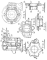
- the illustrated arrangement comprises a turbine housing including a casing 1 only the downstream portion of which is shown, a cover plate 2, and an exhaust outlet pipe 3.
- the casing 1 defines a turbine chamber in which a turbine wheel (not shown) is rotatably supported. Exhaust gas is fed from an exhaust inlet (not shown) through the turbine chamber and over the turbine wheel so as to cause it to rotate. The exhaust gas continues from the turbine chamber into the outlet pipe 3.
- the casing 1 defines an upstream portion 4 of a bypass passageway, that portion being blocked by a poppet valve 5 located inside a chamber 6.
- An insert 7 is located within the exhaust outlet pipe 3 so as to define with that outlet pipe 3 an annular chamber 8 that communicates with the chamber 6 such that gas flowing into the chamber 6 is distributed to the annular chamber 8 and issues into the outlet pipe 3 through an annular gap 9 defined between a downstream edge 10 of the insert.
- An outwardly tapering portion 11 of the insert 7 provides a relatively smooth transition from the upstream portion of the insert 7 which is of relatively small diameter and the downstream edge 10 of the insert 7 which is of relatively larger diameter.
- the cross-sectional flow area of the gap 9 is preferably between 11 ⁇ 2 times and 2 times the cross-sectional area of the upstream portion 4 of the bypass passageway.
- a casing 13 houses a turbine wheel (not shown) and defines an upstream portion 14 of a bypass passageway.
- a poppet valve 15 closes the downstream end of the passageway portion 14. When the valve 15 is open gas within the passageway 14 enters a chamber 16 defined between the casing 13 and a cast cover plate 17.
- An exhaust outlet pipe 18 is secured to the cover plate 17 by bolts 19.
- the cover plate is formed as a casting and defines an annular portion 20 of the bypass passageway, the annular portion 20 reducing in radial width towards an annular slot 21 through which gas issues into the exhaust outlet pipe 18.
- Radially extending struts 22 support a radially inner wall 23 of the cover plate 17, the radially inner wall 23 defining an upstream portion of the exhaust outlet.
- the surface 23 tapers outwards towards the downstream portion of the outlet into which the gas issues from the slot 21.
- the casing can be formed by casting without the provision of the slot 21.
- the annular slot 21 may then be formed by a lathe cut, metal being removed until the slot being cut breaks through and connects with the annular chamber 20.
- Figs. 2 and 3 are similar to that of Fig. 1 in terms of the way in which exhaust gases are directed through the main outlet from the turbine chamber and from the bypass passageway.
- Gas issuing from the slot 21 is directed generally parallel to the axis of the tubular outlet pipe 18 and thus does not significantly disrupt the flow of gas from the turbine.
- FIGs. 4 and 5 illustrate a third embodiment of the invention in which a tubular insert 24 is clamped between the housing casing 25 and a cast cover plate 26.
- An exhaust outlet pipe 27 is secured to the cover plate 26 by bolts 28.
- the insert 24 is formed at its inner end with an annular shoulder 29 which abuts against a corresponding annular shoulder 30 provided by the casing 25, and at its outer end with 6 equi-spaced radially extending webs 31 (only one of which is shown) which abut against a radial shoulder 32 formed in the cover plate 26.
- Gaskets may be located between the insert 24 and the casing 25 and cover plate 26 to ensure the insert 24 is tightly held between the two.
- An annular portion 33 of a bypass channel is defined between the insert 24 and both the casing 25 and cover plate 26, that portion of the channel 33 defined between the insert 24 and the cover plate 26 narrowing towards its downstream end.
- Figs. 6 to 9 illustrate cast member which is used to fabricate a component of a fourth embodiment of the invention which is a modification of that shown in Figs. 4 and 5.
- the single cast member illustrated comprises a tubular portion 34 and an annular portion 35 and replaces the separate tubular insert 24 and cover plate 26 described above.
- the tubular portion 34 and annular portion 35 are joined together by 6 webs 36.
- the cast member is machined as shown partially by the dotted lines in Fig. 8 to give the finished component.
- a cut, indicated by reference 37 is made to open up an annular slot between the webs 36 to communicate the bypass channel (not shown) with the exhaust outlet (not shown).
- the end of the tubular portion 34 is machined as shown by the dotted line 38 to provide an annular shoulder for location in the turbine housing casing (not shown).
- Figs. 4 to 9 function in a similar manner to the previously described embodiments of the invention in the way that exhaust gases are directed through the main outlet from the turbine chamber and from the bypass passageway.
- downstream portions of both the tubular insert 24 and the tubular portion 34 taper radially outwards to provide a relatively smooth transition for exhaust gas exiting the turbine and entering the exhaust outlet.
- gas issuing from the respective bypass channels is directed generally parallel to the axis of the exhaust outlet to minimise disruption in the flow of gas from the turbine.
Landscapes
- Engineering & Computer Science (AREA)
- Chemical & Material Sciences (AREA)
- Combustion & Propulsion (AREA)
- Mechanical Engineering (AREA)
- General Engineering & Computer Science (AREA)
- Supercharger (AREA)
Claims (3)
- Turbolader, der folgendes aufweist: ein Turbinengehäuse, das eine Turbinenkammer definiert, einen Abgaseinlaß in die Turbinenkammer, einen Abgasauslaß (3, 7; 23, 18; 24, 27) aus der Turbinenkammer, einen Durchgang (4, 6, 8; 14, 16, 20; 33), der sich zwischen dem Einlaß und dem Auslaß (3, 7; 23, 18; 24, 27) erstreckt und die Kammer umgeht, ein Ventil (5; 15), das im Durchgang (4, 6, 8; 14, 16, 20; 33) angebracht ist, Mittel zur Steuerung des Ventils (5; 15) zum selektiven Öffnen und Schließen des Durchgangs (4, 6, 8; 14, 16, 20; 33), dadurch gekennzeichnet, daß:wodurch die Unterbrechung im Gasstrom aus der Turbinenkammer im Auslaß (3, 7; 23, 18; 24, 27) auf ein Minimum gesenkt wird.(i) der Durchgang (4, 6, 8; 14, 16, 20; 33) einen ringförmigen Abschnitt (8; 20; 33) aufweist, der an seinem oberhalb befindlichen Ende mit einer Kammer (6; 16) in Verbindung steht, die um das Ventil (5; 15) definiert wird, und sich an seinem unterhalb befindlichen Ende in einer solchen Richtung in den Auslaß (3, 7; 23, 18; 24, 27) öffnet, daß Gas, das aus dem ringförmigen Abschnitt (8; 20; 33) des Durchgangs (4, 6, 8; 14, 16, 20; 33) austritt, im wesentlichen parallel zur Achse der Turbine geleitet wird, in der Richtung, in der das Gas aus der Turbinenkammer durch den Auslaß (3, 7; 23, 18; 24, 27) strömt,(ii) der ringförmige Abschnitt (8; 20; 33) des Durchgangs koaxial mit und in Radialrichtung außerhalb eines ersten Abschnitts (7; 23) des Auslasses (3, 7; 23, 18; 24, 27) angeordnet ist und sich an einem zweiten Abschnitt (3; 18) des Auslasses (3, 7; 23, 18; 24, 27) unterhalb des ersten Abschnitts (7; 23) öffnet,(iii) der ringförmige Abschnitt (8; 20; 33) des Durchgangs (4, 6, 8; 14, 16, 20; 33) in der Radialbreite hin zu seinem unterhalb befindlichen Ende kleiner wird, und(iv) der erste Abschnitt (7; 23) des Auslasses sich in Radialrichtung nach außen hin zum unterhalb befindlichen Ende des ringförmigen Abschnitts (8; 20; 33) des Durchgangs (4, 6, 8; 14, 16, 20; 33) und des zweiten Abschnitts (3; 18) des Auslasses (3, 7; 23, 18; 24, 27) verjüngt,
- Turbolader nach Anspruch 1, bei dem der erste Abschnitt (7) des Auslasses (3, 7) einen ringförmigen Einsatz (7) aufweist, der sich innerhalb eines Abgasauslaßrohres (3) befindet, wobei der ringförmige Abschnitt (8) des Umgehungsdurchgangs (4, 6, 8) zwischen dem rohrförmigen Einsatz (7) und dem Auslaßrohr (3) definiert wird, wobei der rohrförmige Einsatz (7) einen unterhalb befindlichen Abschnitt (11) hat, der in Radialrichtung nach außen divergiert, um die Verjüngung zu definieren.
- Turbolader nach Anspruch 1, bei dem der ringförmige Abschnitt (20) des Umgehungsdurchgangs (14, 16, 18) durch eine Deckplatte (17) definiert wird, die am Turbinengehäuse befestigt ist, wobei die Deckplatte mit in Radialrichtung nach innen verlaufenden Streben (22) versehen ist, die eine in Radialrichtung innere Wand (23) der Deckplatte (17) tragen, wobei die Wand (23) einen oberhalb befindlichen Abschnitt des Abgasauslasses definiert.
Applications Claiming Priority (2)
| Application Number | Priority Date | Filing Date | Title |
|---|---|---|---|
| GB939311584A GB9311584D0 (en) | 1993-06-04 | 1993-06-04 | Turbo-charger |
| GB9311584 | 1993-06-04 |
Publications (2)
| Publication Number | Publication Date |
|---|---|
| EP0627550A1 EP0627550A1 (de) | 1994-12-07 |
| EP0627550B1 true EP0627550B1 (de) | 2001-03-21 |
Family
ID=10736660
Family Applications (1)
| Application Number | Title | Priority Date | Filing Date |
|---|---|---|---|
| EP94304037A Expired - Lifetime EP0627550B1 (de) | 1993-06-04 | 1994-06-06 | Turbolader |
Country Status (5)
| Country | Link |
|---|---|
| US (1) | US5579643A (de) |
| EP (1) | EP0627550B1 (de) |
| JP (1) | JP3748903B2 (de) |
| DE (1) | DE69426901T2 (de) |
| GB (1) | GB9311584D0 (de) |
Families Citing this family (23)
| Publication number | Priority date | Publication date | Assignee | Title |
|---|---|---|---|---|
| FR2728937A1 (fr) * | 1994-12-28 | 1996-07-05 | Aisin Seiki | Structure de robinet-vanne pour turbocompresseur |
| JP3624521B2 (ja) * | 1996-02-29 | 2005-03-02 | アイシン精機株式会社 | ターボチャージャ |
| SE519433C2 (sv) * | 1997-07-07 | 2003-02-25 | Scania Cv Ab | Hus för turboöverladdare för förbränningsmotor samt turboöverladdare |
| US6202413B1 (en) | 1999-02-04 | 2001-03-20 | Cummins Engine Company, Inc. | Multiple nozzle ejector for wastegated turbomachinery |
| US6295816B1 (en) | 2000-05-24 | 2001-10-02 | General Electric Company | Turbo-charged engine combustion chamber pressure protection apparatus and method |
| US8047772B2 (en) * | 2005-03-30 | 2011-11-01 | Honeywell International Inc. | Variable geometry turbine for a turbocharger and method of controlling the turbine |
| DE102006001571A1 (de) * | 2006-01-12 | 2007-08-02 | Robert Bosch Gmbh | Strömungsoptimierter Bypass für Strömungsmaschinen |
| US8206133B2 (en) * | 2008-08-12 | 2012-06-26 | GM Global Technology Operations LLC | Turbocharger housing with integral inlet and outlet openings |
| CN101598038B (zh) * | 2009-07-03 | 2012-05-09 | 康跃科技股份有限公司 | 涡轮增压器双层流道变截面涡轮机 |
| US9759228B2 (en) * | 2009-10-16 | 2017-09-12 | GM Global Technology Operations LLC | Turbocharger and air induction system incorporating the same and method of using the same |
| US8353664B2 (en) | 2009-11-03 | 2013-01-15 | Honeywell International Inc. | Turbocharger with annular rotary bypass valve for the turbine |
| US8534994B2 (en) | 2010-12-13 | 2013-09-17 | Honeywell International Inc. | Turbocharger with divided turbine housing and annular rotary bypass valve for the turbine |
| JP5988709B2 (ja) * | 2012-06-05 | 2016-09-07 | 日野自動車株式会社 | タービンハウジング、ターボチャージャー、および、タービンハウジングと排気管との接続構造 |
| US9593690B2 (en) * | 2013-06-26 | 2017-03-14 | Honeywell International Inc. | Turbocharger with an annular rotary bypass valve |
| US9689397B2 (en) * | 2014-06-13 | 2017-06-27 | GM Global Technology Operations LLC | Turbine outlet diffuser |
| CN104110300B (zh) * | 2014-08-06 | 2017-05-10 | 无锡康明斯涡轮增压技术有限公司 | 涡轮增压器 |
| US10605110B2 (en) * | 2015-10-14 | 2020-03-31 | Mechanical Dynamics & Analysis Llc | Bypass valve assembly for turbine generators |
| JP6457977B2 (ja) * | 2016-06-28 | 2019-01-23 | 本田技研工業株式会社 | タービン |
| US10731546B2 (en) * | 2017-02-06 | 2020-08-04 | Borgwarner Inc. | Diffuser in wastegate turbine housings |
| GB201717127D0 (en) * | 2017-10-18 | 2017-11-29 | Cummins Ltd | Turbine |
| DE102019001798B4 (de) * | 2019-03-11 | 2024-10-31 | BorgWarner lnc. | Turbolader und Turbinengehäuse hierfür |
| DE102021201115A1 (de) | 2021-02-05 | 2022-08-11 | Rolls-Royce Solutions GmbH | Krümmer, Strömungsmaschine mit einem solchen Krümmer, Abgasturbolader mit einer solchen Strömungsmaschine, und Brennkraftmaschine mit einem solchen Krümmer |
| DE112023002623T5 (de) * | 2022-09-07 | 2025-04-10 | Ihi Corporation | Turbine |
Family Cites Families (11)
| Publication number | Priority date | Publication date | Assignee | Title |
|---|---|---|---|---|
| US3994620A (en) * | 1975-06-30 | 1976-11-30 | Wallace-Murray Corporation | Variable exducer turbine control |
| JPS5419007A (en) * | 1977-07-13 | 1979-02-13 | Hitachi Ltd | Turbocharger bypass device |
| JPS5525505A (en) * | 1978-08-10 | 1980-02-23 | Ishikawajima Harima Heavy Ind Co Ltd | Supercharger provided on turbine outlet with ejector |
| JPS5951652B2 (ja) * | 1979-01-29 | 1984-12-15 | 日産自動車株式会社 | タ−ボチヤ−ジヤのウエストゲ−トバルブ下流の整流構造 |
| DE2939152C2 (de) * | 1979-09-27 | 1983-10-20 | Bayerische Motoren Werke AG, 8000 München | Turbine eines Abgasturboladers für Brennkraftmaschinen |
| DE3007053C2 (de) * | 1980-02-26 | 1982-11-18 | Audi Nsu Auto Union Ag, 7107 Neckarsulm | Abgasturbolader für Brennkraftmaschinen |
| JPS58117322A (ja) * | 1982-01-06 | 1983-07-12 | Hitachi Ltd | 排気タ−ビン式過給機 |
| DE3803010A1 (de) * | 1988-02-02 | 1989-08-10 | Audi Ag | Turbine eines abgasturboladers |
| DE3941715A1 (de) * | 1989-12-18 | 1991-06-20 | Porsche Ag | Abgasturbolader fuer eine brennkraftmaschine |
| JPH05209530A (ja) * | 1992-01-30 | 1993-08-20 | Yanmar Diesel Engine Co Ltd | エンジンのエアタービン装置 |
| US5311749A (en) * | 1992-04-03 | 1994-05-17 | United Technologies Corporation | Turbine bypass working fluid admission |
-
1993
- 1993-06-04 GB GB939311584A patent/GB9311584D0/en active Pending
-
1994
- 1994-06-03 US US08/253,536 patent/US5579643A/en not_active Expired - Lifetime
- 1994-06-06 EP EP94304037A patent/EP0627550B1/de not_active Expired - Lifetime
- 1994-06-06 JP JP14871494A patent/JP3748903B2/ja not_active Expired - Fee Related
- 1994-06-06 DE DE69426901T patent/DE69426901T2/de not_active Expired - Lifetime
Also Published As
| Publication number | Publication date |
|---|---|
| JPH0771263A (ja) | 1995-03-14 |
| US5579643A (en) | 1996-12-03 |
| DE69426901T2 (de) | 2001-08-16 |
| DE69426901D1 (de) | 2001-04-26 |
| EP0627550A1 (de) | 1994-12-07 |
| JP3748903B2 (ja) | 2006-02-22 |
| GB9311584D0 (en) | 1993-07-21 |
Similar Documents
| Publication | Publication Date | Title |
|---|---|---|
| EP0627550A1 (de) | Turbolader | |
| US5943864A (en) | Exhaust gas turbocharger for an internal combustion engine | |
| EP2189722B1 (de) | Gasturbine mit brennkammer | |
| US5533487A (en) | Dynamic enhancement of EGR flow in an internal combustion engine | |
| US5758500A (en) | Exhaust gas turbochanger for an internal combustion engine | |
| EP1914393A2 (de) | Dampfventil und Dampfturbinenanlage | |
| AU656790B2 (en) | An improved flow control system | |
| GB2059515A (en) | A Turbine of an Exhaust-driven Supercharger | |
| US5870896A (en) | Combined valve configuration for steam cycle units | |
| EP0875705A3 (de) | Strömungsdiffusor und Ventil | |
| US6101812A (en) | Motor brake arrangement for a turbocharged engine | |
| JPS5951652B2 (ja) | タ−ボチヤ−ジヤのウエストゲ−トバルブ下流の整流構造 | |
| SE510173C2 (sv) | Ventilanordning | |
| US4169355A (en) | Turbocharger wastegate valve | |
| CN111512031B (zh) | 涡轮机 | |
| KR102805774B1 (ko) | 가스 유동 및 사운드 제어 밸브 및 배기 가스 시스템 | |
| CA2211146A1 (en) | Improved automatic recirculation valve | |
| US20180080324A1 (en) | Fluidically controlled steam turbine inlet scroll | |
| JP2007023894A (ja) | ターボ過給機 | |
| JP4524970B2 (ja) | エンジンの排気系構造 | |
| JP7761157B2 (ja) | タービン | |
| JPS6278434A (ja) | 可変容量ラジアルタ−ビン過給機 | |
| JP3341189B2 (ja) | 弁部材内蔵型ストレ―ナ | |
| CN112888842B (zh) | 适配器 | |
| RU2144986C1 (ru) | Устройство для выпуска газов из турбомашины |
Legal Events
| Date | Code | Title | Description |
|---|---|---|---|
| PUAI | Public reference made under article 153(3) epc to a published international application that has entered the european phase |
Free format text: ORIGINAL CODE: 0009012 |
|
| AK | Designated contracting states |
Kind code of ref document: A1 Designated state(s): DE FR GB IT |
|
| 17P | Request for examination filed |
Effective date: 19950516 |
|
| 17Q | First examination report despatched |
Effective date: 19960304 |
|
| APAB | Appeal dossier modified |
Free format text: ORIGINAL CODE: EPIDOS NOAPE |
|
| APAB | Appeal dossier modified |
Free format text: ORIGINAL CODE: EPIDOS NOAPE |
|
| APAD | Appeal reference recorded |
Free format text: ORIGINAL CODE: EPIDOS REFNE |
|
| APCB | Communication from the board of appeal sent |
Free format text: ORIGINAL CODE: EPIDOS OBAPE |
|
| APCB | Communication from the board of appeal sent |
Free format text: ORIGINAL CODE: EPIDOS OBAPE |
|
| APAB | Appeal dossier modified |
Free format text: ORIGINAL CODE: EPIDOS NOAPE |
|
| APCB | Communication from the board of appeal sent |
Free format text: ORIGINAL CODE: EPIDOS OBAPE |
|
| GRAG | Despatch of communication of intention to grant |
Free format text: ORIGINAL CODE: EPIDOS AGRA |
|
| GRAG | Despatch of communication of intention to grant |
Free format text: ORIGINAL CODE: EPIDOS AGRA |
|
| GRAH | Despatch of communication of intention to grant a patent |
Free format text: ORIGINAL CODE: EPIDOS IGRA |
|
| GRAH | Despatch of communication of intention to grant a patent |
Free format text: ORIGINAL CODE: EPIDOS IGRA |
|
| GRAA | (expected) grant |
Free format text: ORIGINAL CODE: 0009210 |
|
| AK | Designated contracting states |
Kind code of ref document: B1 Designated state(s): DE FR GB IT |
|
| PG25 | Lapsed in a contracting state [announced via postgrant information from national office to epo] |
Ref country code: IT Free format text: LAPSE BECAUSE OF FAILURE TO SUBMIT A TRANSLATION OF THE DESCRIPTION OR TO PAY THE FEE WITHIN THE PRE;WARNING: LAPSES OF ITALIAN PATENTS WITH EFFECTIVE DATE BEFORE 2007 MAY HAVE OCCURRED AT ANY TIME BEFORE 2007. THE CORRECT EFFECTIVE DATE MAY BE DIFFERENT FROM THE ONE RECORDED.SCRIBED TIME-LIMIT Effective date: 20010321 |
|
| REF | Corresponds to: |
Ref document number: 69426901 Country of ref document: DE Date of ref document: 20010426 |
|
| ET | Fr: translation filed | ||
| REG | Reference to a national code |
Ref country code: GB Ref legal event code: IF02 |
|
| PLBE | No opposition filed within time limit |
Free format text: ORIGINAL CODE: 0009261 |
|
| STAA | Information on the status of an ep patent application or granted ep patent |
Free format text: STATUS: NO OPPOSITION FILED WITHIN TIME LIMIT |
|
| 26N | No opposition filed | ||
| APAH | Appeal reference modified |
Free format text: ORIGINAL CODE: EPIDOSCREFNO |
|
| PGFP | Annual fee paid to national office [announced via postgrant information from national office to epo] |
Ref country code: DE Payment date: 20110629 Year of fee payment: 18 |
|
| REG | Reference to a national code |
Ref country code: DE Ref legal event code: R119 Ref document number: 69426901 Country of ref document: DE Effective date: 20130101 |
|
| PG25 | Lapsed in a contracting state [announced via postgrant information from national office to epo] |
Ref country code: DE Free format text: LAPSE BECAUSE OF NON-PAYMENT OF DUE FEES Effective date: 20130101 |
|
| PGFP | Annual fee paid to national office [announced via postgrant information from national office to epo] |
Ref country code: GB Payment date: 20130627 Year of fee payment: 20 |
|
| PGFP | Annual fee paid to national office [announced via postgrant information from national office to epo] |
Ref country code: FR Payment date: 20130702 Year of fee payment: 20 |
|
| REG | Reference to a national code |
Ref country code: GB Ref legal event code: PE20 Expiry date: 20140605 |
|
| PG25 | Lapsed in a contracting state [announced via postgrant information from national office to epo] |
Ref country code: GB Free format text: LAPSE BECAUSE OF EXPIRATION OF PROTECTION Effective date: 20140605 |