EP0627312A2 - Verfahren und Gerät zum Parallel-Synchronbetrieb einer Offsetdruckmaschine für Bahnen - Google Patents
Verfahren und Gerät zum Parallel-Synchronbetrieb einer Offsetdruckmaschine für Bahnen Download PDFInfo
- Publication number
- EP0627312A2 EP0627312A2 EP94250111A EP94250111A EP0627312A2 EP 0627312 A2 EP0627312 A2 EP 0627312A2 EP 94250111 A EP94250111 A EP 94250111A EP 94250111 A EP94250111 A EP 94250111A EP 0627312 A2 EP0627312 A2 EP 0627312A2
- Authority
- EP
- European Patent Office
- Prior art keywords
- clutch
- synchronous operation
- machine
- control panel
- web offset
- Prior art date
- Legal status (The legal status is an assumption and is not a legal conclusion. Google has not performed a legal analysis and makes no representation as to the accuracy of the status listed.)
- Granted
Links
Images

Classifications
-
- B—PERFORMING OPERATIONS; TRANSPORTING
- B41—PRINTING; LINING MACHINES; TYPEWRITERS; STAMPS
- B41F—PRINTING MACHINES OR PRESSES
- B41F33/00—Indicating, counting, warning, control or safety devices
- B41F33/0009—Central control units
Definitions
- This invention relates to a method and an apparatus for matching the rotational phases of plate cylinders of individual printing presses, for example, when two web offset printing presses are operated in parallel and in synchronization.
- a web offset printing press as shown in Fig.4, comprises a splicer infeed 1 for web feed and tension adjustment, for example, a 4-stage printing unit 2 for monoor multicolor printing, a dryer 4, and a cooling drag 5 for cooling.
- the machine shown in Fig.4 further comprises first and second 2-stage folders, and the splicer infeed 1, the printing unit 2, the cooling drag 5, and the first and second folders 6 are driven by a motor 3.
- a line shaft between the printing unit 2 and the dryer 4 is provided with a drive clutch 7, and the first and second folders 6 are also provided with folder clutches 7F.
- the drive clutch 7 is adjust starting under slow rotation, and the folder clutch 7F is adjust timing for phase matching between the printing unit 2 and the plate cylinder.
- Timing of the folder clutch 7F is matched as follows. Since the plate cylinder makes one turn for two turns of a drive shaft of the motor 3, after tuning on the drive clutch 7, the folder clutch 7F is actuated in response to a pulse output from a detector 8 such as a limit switch for detecting two turns of the drive shaft by a pulse. Since there are two states (180° rotation or 360° rotation) in the rotational position of the plate cylinder, the folder 6 is set when it is actuated so that the folder clutch 7F is not actuated with a phase difference of half turn of the plate cylinder.
- pulse output of the detector 8 of the drive clutch 7 and pulse output of the detector 8F of the folder clutch 7F are displayed on lamps on a control panel to detect a condition where the lamps simultaneously light.
- a plurality of printing presses for example, two of such a web offset printing press are disposed in parallel and operated in synchronization, and a printed matter is conducted to the folder of one printing press, thereby achieving a parallel synchronous operation method.
- machine A one web offset printing press
- machine B the other web offset printing press
- a primary object of the present invention is to provide a method and apparatus for parallel synchronous operation of web offset printing presses which enables exact phase matching by a simple operation with a reduced burden to the operator.
- connection of a drive clutch and a folder clutch of the machine A alone, and connection of a drive clutch of the machine B alone are made detectable on a synchronous operation control panel, phases of the machines A and B are matched under control of the control panel, and a synchronous operation clutch is connected to achieve synchronous operation.
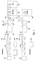
- Fig.1 shows main and sub-web offset printing presses, that is, machines A and B, which are put on parallel synchronous operation.
- the machines A and B individually can be operated independent of each other.
- the machine A as in Fig.4, comprises a splicer infeed 1A, a 4-stage printing unit 2A, a motor 3A, a drive clutch 7A, a dryer 4A, a cooling drag 5A, two folders 6A, a folder clutch 7FA, and an independent operation control panel 12A for instructing and displaying operation condition, clutch operation, and the like.
- the machine B comprises a splicer infeed 1B, a printing unit 2B, a motor 3B, a drive clutch 7B, a dryer 4B, a cooling drag 5B, a folder 6B, a folder clutch 7FB, and an independent operation control panel 12B.
- the drive clutches 7A and 7B and the folder clutches 7FA and 7FB are individually provided with detectors 8A, 8B, 8FA, and 8FB such as limit switches, which detect ON/OFF of each clutch and rotational phase as a connection timing. That is, "clutch ON" can be detected by detecting the shaft rotation, and the phase of the printing unit with respect to the plate cylinder can be detected by the actuation of the drive clutches 7A and 7B and the folder clutches 7FA and 7FB.
- 0° or 180° of the plate cylinder can be determined by connection of the drive clutches 7A and 7B or the folder clutches 7FA and 7FB.
- Each of the clutches 7A, 7B, 7FA, and 7FB is preferably an engaging clutch which engages only at a position in the rotational direction. In this case, with the clutch ON, the relative rotational positions of the line shafts of the drive side and driven side are fixed, but the rotational position of the plate cylinder is 0° or 180°.
- actuation of the drive clutches 7A and 7B and the folder clutches 7FA and 7FB can be in line with rotational position of 0° or 180° of the plate cylinder, and the phase of each of the clutches and the folders 6A and 6B with respect to the plate cylinder can be matched if the timing of clutch ON/OFF is matched on the individual control panels 12A and 12B.
- a new line shaft 9L and synchronous operation clutches 10X, 10Y, and 10Z for connecting the machines A and B, and a synchronous operation control panel 13 are provided. Further, detectors 11X, 11Y, and 11Z are provided to detect ON/OFF of the synchronous operation clutches 10X, 10Y, and 10Z.
- the synchronous operation clutch 10Y is to turn on and off between the machine A and the line shaft 9L
- the synchronous operation clutch 10Z is to turn on and off between the machine B and the line shaft 9L
- the synchronous operation clutch 10X is to turn on and off a guide drive roll (not shown) for conducting web from the machine B to the folder 6A during synchronous operation.
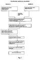
- Parallel synchronous operation of the machines A and B shown in Fig.1 is carried out according to the flow chart shown in Fig.2.
- (1S) by the function of the machine A control panel 12A, the machine A is operated at a slow rotation of a very low rotational speed, and the drive clutch 7A and the folder clutch 7FA are connected under matched timing as described above.
- the drive clutch 7A and the folder clutch 7FA are connected, the machine A is operated at a slow rotation, and outputs of the detectors 8A and 8FA are detected.
- Simultaneous ON condition of the outputs of the both detectors 8F and 8FA means a phase matching. If not, while continuing slow operation, the drive clutch 7A is once released and, after a predetermined time, the drive clutch 7A is connected again, thereby achieving connection of the clutches 7A and 7FA of the machine A side with matched timing.
- (2S) by the function of the machine A control panel 12A, the machine A is operated at a slow rotation by the function of the machine B control panel 12B, and the drive clutch 7B is connected. Since, after clutch connection under slow rotation of the individual machines A and B, phases of the clutches 7A and 7FA are in line and the clutch 7B is actuated, the machines are stopped. This prevents the operator from an accident.
- (5S) the machine A is operated at slow rotation by operating the machine A control panel 12A, and an ON timing of the synchronous operation clutch 10Y is detected by the detectors 8A and 8FA to stop the machine A automatically.
- the detectors 8A, 8FA, and 8B detect ON/OFF timing of the clutches 7A, 7FA, and 7B, but only ON/OFF of the detectors 11X, 11Y, and 11Z.
- the drive clutches 7A and 7B, the folder clutches 7FA and 7FB, and the synchronous operation clutches 10Y and 10Z are preferably an engaging clutch which engages at a position.
- the present embodiment describes an example in which the machine A is used as a main machine, and the web from the machine B is delivered to the folder of the machine A and, therefore, in synchronous operation, the folder 6B, the folder clutch 7FB, and the detector 8FB are not used.
- the operation shown in Fig.2 is for an existing apparatus for independent operation of the machines A and B which is improved for synchronous operation.
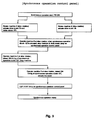
- the operation may be such that (10S) by the instruction of turning on the pushbutton P/B on the synchronous operation control panel 13, the drive clutch 7A and the folder 7FA of the machine A are actuated, (2S) the drive clutch 7B of the machine B is actuated, (4S) the machine B is operated at slow rotation to actuate the synchronous operation clutch 10Z, the clutch lamp on the synchronous operation control panel 13 is blinked, (5S) the machine A is operated at slow rotation, the timing position of the synchronous operation clutch 10Y is detected, and the machine A is stopped, (7S) the machine B is operated at slow rotation, the ON timing of the synchronous operation clutch 10Y is detected to actuate the clutch 10Y, and (8S) the clutch lamp is blinked to achieve a synchronous operation ready condition.
- the operation may be such that (5S) the machine B is operated at slow rotation, the timing position of the synchronous operation clutch 10Y is detected to stop the machine B, (7S) the machine A is operated at slow rotation, and the ON timing position of the synchronous operation clutch 10Y is detected to actuate the clutch 10Y.
- synchronous operation can also be easily achieved when the synchronous operation clutch 10Z is not provided and the machine B and the line shaft 9L are always connected, or when the synchronous operation clutch 10Y is not provided and the machine A and the line shaft are always connected.
- the present embodiment eliminates the need for a tedious work by the operator for clutch phase matching of the machines A and B which is required by the prior art, ON/OFF checking is not required, timing and ON/OFF of the clutches necessary for synchronous operation can be placed under the control of the synchronous operation control panel, thereby achieving improved operability and safety and saving of time.
Landscapes
- Inking, Control Or Cleaning Of Printing Machines (AREA)
- Controlling Rewinding, Feeding, Winding, Or Abnormalities Of Webs (AREA)
- Rotary Presses (AREA)
Applications Claiming Priority (3)
| Application Number | Priority Date | Filing Date | Title |
|---|---|---|---|
| JP11563793A JP3313451B2 (ja) | 1993-05-18 | 1993-05-18 | 輪転印刷機の並列同期運転方法及びその装置 |
| JP11563793 | 1993-05-18 | ||
| JP115637/93 | 1993-05-18 |
Publications (4)
| Publication Number | Publication Date |
|---|---|
| EP0627312A2 true EP0627312A2 (de) | 1994-12-07 |
| EP0627312A3 EP0627312A3 (de) | 1995-04-12 |
| EP0627312B1 EP0627312B1 (de) | 1997-06-18 |
| EP0627312B2 EP0627312B2 (de) | 2002-01-02 |
Family
ID=14667578
Family Applications (1)
| Application Number | Title | Priority Date | Filing Date |
|---|---|---|---|
| EP94250111A Expired - Lifetime EP0627312B2 (de) | 1993-05-18 | 1994-04-28 | Verfahren zum Parallel-Synchronbetrieb einer Offsetdruckmaschine für Bahnen |
Country Status (5)
| Country | Link |
|---|---|
| US (1) | US5415093A (de) |
| EP (1) | EP0627312B2 (de) |
| JP (1) | JP3313451B2 (de) |
| AT (1) | ATE154546T1 (de) |
| DE (1) | DE69403863T2 (de) |
Cited By (2)
| Publication number | Priority date | Publication date | Assignee | Title |
|---|---|---|---|---|
| DE19958089A1 (de) * | 1999-12-02 | 2001-06-07 | Heidelberger Druckmasch Ag | Druckmaschinenanordnung mit einer ersten und einer zweiten Druckmaschine |
| WO2003004272A1 (de) | 2001-07-02 | 2003-01-16 | Koenig & Bauer Aktiengesellschaft | Druckmaschine mit mehreren sektionen |
Families Citing this family (7)
| Publication number | Priority date | Publication date | Assignee | Title |
|---|---|---|---|---|
| DE19537587C2 (de) * | 1995-10-09 | 1998-02-26 | Koenig & Bauer Albert Ag | Antriebsregeleinrichtung für einen Mehrmotorenantrieb einer Druckmaschine |
| JP3183871B2 (ja) * | 1999-08-30 | 2001-07-09 | 株式会社東京機械製作所 | 輪転機のネットワーク型同期制御装置 |
| US20030151832A1 (en) * | 2002-01-14 | 2003-08-14 | Arthur Berman | Method and apparatus for enclosing optical assemblies |
| JP4473033B2 (ja) * | 2004-04-21 | 2010-06-02 | 株式会社小森コーポレーション | 同期制御方法及び装置 |
| JP2009023098A (ja) * | 2007-07-17 | 2009-02-05 | Komori Corp | 巻紙輪転印刷機の同期制御方法及び装置 |
| US10124089B2 (en) | 2012-09-21 | 2018-11-13 | Washington University | Method of making biomedical patches with spatially arranged fibers |
| US10632228B2 (en) | 2016-05-12 | 2020-04-28 | Acera Surgical, Inc. | Tissue substitute materials and methods for tissue repair |
Family Cites Families (10)
| Publication number | Priority date | Publication date | Assignee | Title |
|---|---|---|---|---|
| GB1593207A (en) * | 1977-03-23 | 1981-07-15 | Harris Corp | Web printing press |
| US4240346A (en) * | 1979-01-29 | 1980-12-23 | Harris Corporation | Web printing press |
| JPS6061263A (ja) * | 1983-09-14 | 1985-04-09 | Miyakoshi Kikai Seisaku Kk | 交換胴タイプ輪転機における原動軸連結位置監視方法 |
| GB2149149A (en) * | 1983-10-28 | 1985-06-05 | Rockwell Graphic Syst | Printing press synchronization |
| JPS61286137A (ja) * | 1985-06-14 | 1986-12-16 | Hitachi Seiko Ltd | 輪転印刷機用の位相合せ装置 |
| DE4017159A1 (de) * | 1990-05-28 | 1991-12-05 | Windmoeller & Hoelscher | Druckmaschine |
| JPH04319441A (ja) * | 1991-04-19 | 1992-11-10 | Hitachi Seiko Ltd | 印刷機の位相合せ装置 |
| DE4127321C2 (de) * | 1991-08-17 | 1999-01-07 | Roland Man Druckmasch | Antrieb für eine Rollen-Rotationsdruckmaschine |
| US5341735A (en) * | 1991-08-17 | 1994-08-30 | Man Roland Druckmaschinen Ag | Rotary printing machine system with synchronized multiple printing machine units or stations |
| DE4232559C2 (de) * | 1992-09-29 | 1994-07-28 | Roland Man Druckmasch | Vorrichtung und Verfahren zum registerhaltigen Kuppeln einer Rollenrotationsdruckmaschine |
-
1993
- 1993-05-18 JP JP11563793A patent/JP3313451B2/ja not_active Expired - Fee Related
-
1994
- 1994-04-28 DE DE69403863T patent/DE69403863T2/de not_active Expired - Lifetime
- 1994-04-28 AT AT94250111T patent/ATE154546T1/de not_active IP Right Cessation
- 1994-04-28 EP EP94250111A patent/EP0627312B2/de not_active Expired - Lifetime
- 1994-05-12 US US08/241,757 patent/US5415093A/en not_active Expired - Lifetime
Cited By (5)
| Publication number | Priority date | Publication date | Assignee | Title |
|---|---|---|---|---|
| DE19958089A1 (de) * | 1999-12-02 | 2001-06-07 | Heidelberger Druckmasch Ag | Druckmaschinenanordnung mit einer ersten und einer zweiten Druckmaschine |
| WO2003004272A1 (de) | 2001-07-02 | 2003-01-16 | Koenig & Bauer Aktiengesellschaft | Druckmaschine mit mehreren sektionen |
| DE10131976A1 (de) * | 2001-07-02 | 2003-01-23 | Koenig & Bauer Ag | Druckmaschine mit mehreren Sektionen |
| US6886823B2 (en) | 2001-07-02 | 2005-05-03 | Koenig & Bauer Aktiengesellschaft | Printing machine with several sections |
| DE10131976B4 (de) * | 2001-07-02 | 2005-12-29 | Koenig & Bauer Ag | Druckmaschine mit mehreren Sektionen |
Also Published As
| Publication number | Publication date |
|---|---|
| EP0627312B2 (de) | 2002-01-02 |
| EP0627312A3 (de) | 1995-04-12 |
| ATE154546T1 (de) | 1997-07-15 |
| JP3313451B2 (ja) | 2002-08-12 |
| EP0627312B1 (de) | 1997-06-18 |
| JPH06328672A (ja) | 1994-11-29 |
| US5415093A (en) | 1995-05-16 |
| DE69403863D1 (de) | 1997-07-24 |
| DE69403863T2 (de) | 1997-10-09 |
Similar Documents
| Publication | Publication Date | Title |
|---|---|---|
| EP0627312B1 (de) | Verfahren und Gerät zum Parallel-Synchronbetrieb einer Offsetdruckmaschine für Bahnen | |
| RU2102242C1 (ru) | Машина печатная ротационная с рулонной подачей бумаги | |
| US5617788A (en) | Switching type continuously operative printing machine | |
| JPH0796289B2 (ja) | オフセツト輪転印刷機の5胴印刷装置用の調節装置 | |
| EP0268857A2 (de) | Steuerungssystem, um in einer Bogenoffsetdruckmaschine automatisch die Druckplatten zu wechseln | |
| US5215014A (en) | Positioning system for rotary folding jaw cylinder adjustment elements in a rotary printing machine | |
| JP2589863B2 (ja) | 印刷機 | |
| JPH025520B2 (de) | ||
| JPS5630863A (en) | Initial alining device in multicolor printer | |
| US2888260A (en) | Registration control apparatus | |
| EP0541144B1 (de) | Rollenwechsler | |
| US2840372A (en) | Automatic control system | |
| US5325774A (en) | Ribbon path indicator system | |
| JP3112149B2 (ja) | 切り換え可能な枚葉紙印刷機の状態監視装置 | |
| US5421257A (en) | Sheet transferring machine for printing machine | |
| JP3546159B2 (ja) | 輪転印刷機におけるモータの同期駆動制御方法及び装置 | |
| EP0990519A3 (de) | Bedieneinheit für eine Steuereinrichtung einer Druckmaschine | |
| DE69417352D1 (de) | Druckschaltvorrichtung für eine Bogendruckmaschine mit einer Wendeeinrichtung | |
| JPS61286137A (ja) | 輪転印刷機用の位相合せ装置 | |
| EP0658425A1 (de) | Bogenübertragungsvorrichtung für eine Druckmaschine | |
| JP3463249B2 (ja) | 横ミシン目入切り方法および装置 | |
| JP2532047Y2 (ja) | 印刷装置の紙通し機構 | |
| EP1992484A2 (de) | Verfahren und Vorrichtung zum Einführen von Papierbahnen für eine Rotationsdruckmaschine | |
| WO2010036627A1 (en) | Simultaneous zero verification for motors in a printing press | |
| JP2516065B2 (ja) | 輪転印刷機のインキ供給源駆動装置 |
Legal Events
| Date | Code | Title | Description |
|---|---|---|---|
| PUAI | Public reference made under article 153(3) epc to a published international application that has entered the european phase |
Free format text: ORIGINAL CODE: 0009012 |
|
| AK | Designated contracting states |
Kind code of ref document: A2 Designated state(s): AT CH DE FR GB IT LI NL SE |
|
| PUAL | Search report despatched |
Free format text: ORIGINAL CODE: 0009013 |
|
| AK | Designated contracting states |
Kind code of ref document: A3 Designated state(s): AT CH DE FR GB IT LI NL SE |
|
| 17P | Request for examination filed |
Effective date: 19950530 |
|
| GRAG | Despatch of communication of intention to grant |
Free format text: ORIGINAL CODE: EPIDOS AGRA |
|
| 17Q | First examination report despatched |
Effective date: 19960903 |
|
| GRAH | Despatch of communication of intention to grant a patent |
Free format text: ORIGINAL CODE: EPIDOS IGRA |
|
| GRAH | Despatch of communication of intention to grant a patent |
Free format text: ORIGINAL CODE: EPIDOS IGRA |
|
| GRAA | (expected) grant |
Free format text: ORIGINAL CODE: 0009210 |
|
| AK | Designated contracting states |
Kind code of ref document: B1 Designated state(s): AT CH DE FR GB IT LI NL SE |
|
| PG25 | Lapsed in a contracting state [announced via postgrant information from national office to epo] |
Ref country code: NL Free format text: LAPSE BECAUSE OF FAILURE TO SUBMIT A TRANSLATION OF THE DESCRIPTION OR TO PAY THE FEE WITHIN THE PRESCRIBED TIME-LIMIT Effective date: 19970618 Ref country code: LI Free format text: LAPSE BECAUSE OF FAILURE TO SUBMIT A TRANSLATION OF THE DESCRIPTION OR TO PAY THE FEE WITHIN THE PRESCRIBED TIME-LIMIT Effective date: 19970618 Ref country code: CH Free format text: LAPSE BECAUSE OF FAILURE TO SUBMIT A TRANSLATION OF THE DESCRIPTION OR TO PAY THE FEE WITHIN THE PRESCRIBED TIME-LIMIT Effective date: 19970618 Ref country code: AT Free format text: LAPSE BECAUSE OF FAILURE TO SUBMIT A TRANSLATION OF THE DESCRIPTION OR TO PAY THE FEE WITHIN THE PRESCRIBED TIME-LIMIT Effective date: 19970618 |
|
| REF | Corresponds to: |
Ref document number: 154546 Country of ref document: AT Date of ref document: 19970715 Kind code of ref document: T |
|
| REG | Reference to a national code |
Ref country code: CH Ref legal event code: NV Representative=s name: PATENTANWALTSBUREAU R. A. MASPOLI Ref country code: CH Ref legal event code: EP |
|
| REF | Corresponds to: |
Ref document number: 69403863 Country of ref document: DE Date of ref document: 19970724 |
|
| ITF | It: translation for a ep patent filed | ||
| ET | Fr: translation filed | ||
| PLBI | Opposition filed |
Free format text: ORIGINAL CODE: 0009260 |
|
| PLBF | Reply of patent proprietor to notice(s) of opposition |
Free format text: ORIGINAL CODE: EPIDOS OBSO |
|
| 26 | Opposition filed |
Opponent name: KBA KOENIG & BAUER-ALBERT AG Effective date: 19980317 Opponent name: MAN ROLAND DRUCKMASCHINEN AG Effective date: 19980317 |
|
| NLR1 | Nl: opposition has been filed with the epo |
Opponent name: KBA KOENIG & BAUER-ALBERT AG Opponent name: MAN ROLAND DRUCKMASCHINEN AG |
|
| PLBF | Reply of patent proprietor to notice(s) of opposition |
Free format text: ORIGINAL CODE: EPIDOS OBSO |
|
| PLBF | Reply of patent proprietor to notice(s) of opposition |
Free format text: ORIGINAL CODE: EPIDOS OBSO |
|
| PLAW | Interlocutory decision in opposition |
Free format text: ORIGINAL CODE: EPIDOS IDOP |
|
| PGFP | Annual fee paid to national office [announced via postgrant information from national office to epo] |
Ref country code: AT Payment date: 20010411 Year of fee payment: 8 |
|
| PGFP | Annual fee paid to national office [announced via postgrant information from national office to epo] |
Ref country code: DE Payment date: 20010423 Year of fee payment: 8 |
|
| PGFP | Annual fee paid to national office [announced via postgrant information from national office to epo] |
Ref country code: NL Payment date: 20010430 Year of fee payment: 8 |
|
| PGFP | Annual fee paid to national office [announced via postgrant information from national office to epo] |
Ref country code: CH Payment date: 20010502 Year of fee payment: 8 |
|
| PLAW | Interlocutory decision in opposition |
Free format text: ORIGINAL CODE: EPIDOS IDOP |
|
| RTI2 | Title (correction) |
Free format text: METHOD FOR PARALLEL SYNCHRONOUS OPERATION OF WEB OFFSET PRINTING PRESSES |
|
| PUAH | Patent maintained in amended form |
Free format text: ORIGINAL CODE: 0009272 |
|
| STAA | Information on the status of an ep patent application or granted ep patent |
Free format text: STATUS: PATENT MAINTAINED AS AMENDED |
|
| REG | Reference to a national code |
Ref country code: GB Ref legal event code: IF02 |
|
| 27A | Patent maintained in amended form |
Effective date: 20020102 |
|
| AK | Designated contracting states |
Kind code of ref document: B2 Designated state(s): AT CH DE FR GB IT LI NL SE |
|
| REG | Reference to a national code |
Ref country code: CH Ref legal event code: AEN Free format text: AUFRECHTERHALTUNG DES PATENTES IN GEAENDERTER FORM |
|
| NLR2 | Nl: decision of opposition | ||
| PG25 | Lapsed in a contracting state [announced via postgrant information from national office to epo] |
Ref country code: DE Free format text: LAPSE BECAUSE OF FAILURE TO SUBMIT A TRANSLATION OF THE DESCRIPTION OR TO PAY THE FEE WITHIN THE PRESCRIBED TIME-LIMIT Effective date: 20020403 |
|
| NLV1 | Nl: lapsed or annulled due to failure to fulfill the requirements of art. 29p and 29m of the patents act | ||
| ET3 | Fr: translation filed ** decision concerning opposition | ||
| REG | Reference to a national code |
Ref country code: CH Ref legal event code: PL |
|
| NLV1 | Nl: lapsed or annulled due to failure to fulfill the requirements of art. 29p and 29m of the patents act | ||
| PGFP | Annual fee paid to national office [announced via postgrant information from national office to epo] |
Ref country code: SE Payment date: 20070404 Year of fee payment: 14 |
|
| PGFP | Annual fee paid to national office [announced via postgrant information from national office to epo] |
Ref country code: GB Payment date: 20070425 Year of fee payment: 14 |
|
| PGFP | Annual fee paid to national office [announced via postgrant information from national office to epo] |
Ref country code: IT Payment date: 20070601 Year of fee payment: 14 |
|
| PGFP | Annual fee paid to national office [announced via postgrant information from national office to epo] |
Ref country code: FR Payment date: 20070411 Year of fee payment: 14 |
|
| PLAB | Opposition data, opponent's data or that of the opponent's representative modified |
Free format text: ORIGINAL CODE: 0009299OPPO |
|
| EUG | Se: european patent has lapsed | ||
| GBPC | Gb: european patent ceased through non-payment of renewal fee |
Effective date: 20080428 |
|
| REG | Reference to a national code |
Ref country code: FR Ref legal event code: ST Effective date: 20081231 |
|
| PG25 | Lapsed in a contracting state [announced via postgrant information from national office to epo] |
Ref country code: FR Free format text: LAPSE BECAUSE OF NON-PAYMENT OF DUE FEES Effective date: 20080430 |
|
| PG25 | Lapsed in a contracting state [announced via postgrant information from national office to epo] |
Ref country code: GB Free format text: LAPSE BECAUSE OF NON-PAYMENT OF DUE FEES Effective date: 20080428 |
|
| PG25 | Lapsed in a contracting state [announced via postgrant information from national office to epo] |
Ref country code: IT Free format text: LAPSE BECAUSE OF NON-PAYMENT OF DUE FEES Effective date: 20080428 |
|
| PG25 | Lapsed in a contracting state [announced via postgrant information from national office to epo] |
Ref country code: SE Free format text: LAPSE BECAUSE OF NON-PAYMENT OF DUE FEES Effective date: 20080429 |