EP1992484A2 - Verfahren und Vorrichtung zum Einführen von Papierbahnen für eine Rotationsdruckmaschine - Google Patents
Verfahren und Vorrichtung zum Einführen von Papierbahnen für eine Rotationsdruckmaschine Download PDFInfo
- Publication number
- EP1992484A2 EP1992484A2 EP08152849A EP08152849A EP1992484A2 EP 1992484 A2 EP1992484 A2 EP 1992484A2 EP 08152849 A EP08152849 A EP 08152849A EP 08152849 A EP08152849 A EP 08152849A EP 1992484 A2 EP1992484 A2 EP 1992484A2
- Authority
- EP
- European Patent Office
- Prior art keywords
- paper
- paper threading
- threading
- unit
- printing
- Prior art date
- Legal status (The legal status is an assumption and is not a legal conclusion. Google has not performed a legal analysis and makes no representation as to the accuracy of the status listed.)
- Withdrawn
Links
- 238000000034 method Methods 0.000 title claims description 14
- 238000001514 detection method Methods 0.000 claims abstract description 71
- 238000011144 upstream manufacturing Methods 0.000 claims description 28
- 101000580370 Homo sapiens RAD52 motif-containing protein 1 Proteins 0.000 description 20
- 102100027420 RAD52 motif-containing protein 1 Human genes 0.000 description 20
- 101100402572 Arabidopsis thaliana MS5 gene Proteins 0.000 description 19
- 101100247657 Arabidopsis thaliana RDM4 gene Proteins 0.000 description 17
- 101100119887 Arabidopsis thaliana FDM1 gene Proteins 0.000 description 12
- 238000009434 installation Methods 0.000 description 12
- 238000010586 diagram Methods 0.000 description 6
- 239000002390 adhesive tape Substances 0.000 description 2
- 230000000694 effects Effects 0.000 description 2
- 238000004804 winding Methods 0.000 description 2
- 101100517194 Arabidopsis thaliana NRPD4 gene Proteins 0.000 description 1
- 101100247656 Arabidopsis thaliana RDM3 gene Proteins 0.000 description 1
- 238000013459 approach Methods 0.000 description 1
- 230000003111 delayed effect Effects 0.000 description 1
- 235000013312 flour Nutrition 0.000 description 1
- 239000012530 fluid Substances 0.000 description 1
- 239000000463 material Substances 0.000 description 1
- 238000005259 measurement Methods 0.000 description 1
- 230000007246 mechanism Effects 0.000 description 1
- 230000002093 peripheral effect Effects 0.000 description 1
Images


Classifications
-
- B—PERFORMING OPERATIONS; TRANSPORTING
- B41—PRINTING; LINING MACHINES; TYPEWRITERS; STAMPS
- B41F—PRINTING MACHINES OR PRESSES
- B41F13/00—Common details of rotary presses or machines
- B41F13/02—Conveying or guiding webs through presses or machines
- B41F13/03—Threading webs into printing machines
-
- B—PERFORMING OPERATIONS; TRANSPORTING
- B65—CONVEYING; PACKING; STORING; HANDLING THIN OR FILAMENTARY MATERIAL
- B65H—HANDLING THIN OR FILAMENTARY MATERIAL, e.g. SHEETS, WEBS, CABLES
- B65H20/00—Advancing webs
- B65H20/16—Advancing webs by web-gripping means, e.g. grippers, clips
-
- B—PERFORMING OPERATIONS; TRANSPORTING
- B65—CONVEYING; PACKING; STORING; HANDLING THIN OR FILAMENTARY MATERIAL
- B65H—HANDLING THIN OR FILAMENTARY MATERIAL, e.g. SHEETS, WEBS, CABLES
- B65H2301/00—Handling processes for sheets or webs
- B65H2301/40—Type of handling process
- B65H2301/41—Winding, unwinding
- B65H2301/414—Winding
- B65H2301/4148—Winding slitting
-
- B—PERFORMING OPERATIONS; TRANSPORTING
- B65—CONVEYING; PACKING; STORING; HANDLING THIN OR FILAMENTARY MATERIAL
- B65H—HANDLING THIN OR FILAMENTARY MATERIAL, e.g. SHEETS, WEBS, CABLES
- B65H2301/00—Handling processes for sheets or webs
- B65H2301/50—Auxiliary process performed during handling process
- B65H2301/52—Auxiliary process performed during handling process for starting
- B65H2301/522—Threading web into machine
-
- B—PERFORMING OPERATIONS; TRANSPORTING
- B65—CONVEYING; PACKING; STORING; HANDLING THIN OR FILAMENTARY MATERIAL
- B65H—HANDLING THIN OR FILAMENTARY MATERIAL, e.g. SHEETS, WEBS, CABLES
- B65H2801/00—Application field
- B65H2801/03—Image reproduction devices
- B65H2801/21—Industrial-size printers, e.g. rotary printing press
Definitions
- the present invention relates to a paper threading method for a rotary press and a paper threading apparatus for a rotary press for threading paper through a paper threading path extending from each of paper supply units through each of separate printing units to a folding unit, for a rotary press having a plurality of paper supply units, a plurality of printing units and at least one folding unit.
- paper threading guides are installed along paper threading paths from the respective paper supply units through the printing units to the folding unit.
- Drive motors are installed at proper spaces in the paper threading guides, and drive rollers are connected to the drive motors to be drive unit of paper threading members which are movable along the paper threading guides.
- the paper threading member includes a paper threading belt, and an attachment which is fitted to a leading end portion of the paper threading belt and is attached with an end portion in the traveling direction of a paper web. The end portion in the traveling direction of the paper web is attached to the attachment by using an adhesive tape or the like, and the paper threading belt is moved by a drive roller installed in the paper threading guide, whereby paper threading is conducted.
- the paper threading guide in the paper threading path includes a plurality of branched portions and merging portions.
- Branch destinations are selected by a fluid pressure cylinder or the like for a plurality of branched portions in the paper threading path, selection and designation of the branch destination is determined according to a plurality of paper threading patterns determined in advance in accordance with the printing specification, and the branch destinations are selectively determined by a control unit in accordance with designation of the paper threading pattern prior to a printing operation.
- sensors which detect arrival of the attachment are provided at an end portion at the paper supply unit side, of the paper threading guide and an end portion at a folding part side, of the paper threading guide to stop the drive motor in the corresponding paper threading path when detecting arrival of the attachment.
- a cutting unit which cuts a paper web parallel with the paper threading direction for example, a slitter device is provided in the paper threading path
- an end portion in a traveling direction of the free paper web which newly occurs by cutting is automatically attached to another paper threading member differing from the paper threading member, which conducts paper threading from the paper supply unit, with an adhesive tape by an automatic attaching unit (automatic catching unit in Patent Document 1), and the other paper threading member is moved along another paper threading guide differing from the paper threading guide along which the above described paper threading member is moved to thereby conduct paper threading.
- a paper web touches a printing cylinder of a printing unit and a paper drawing roller which are present in a paper threading path. Therefore, the printing cylinder of the printing unit and the paper drawing roller need to be driven at a peripheral speed substantially the same as the paper threading speed of the web paper so as not to interfere with the movement of the paper web.
- Japanese Patent Laid-Open No. 7-9673 "DRAW-IN DEVICE FOR DRAWING MATERIAL ROLL INTO PRINTING MACHINE AND METHOD THEREOF" (which will be referred to as reference publication 1 hereinafter) proposes (1) a mode of changing start timing of paper threading for each paper threading path, (2) a mode of changing a speed of paper threading for each paper threading path, and (3) a paper threading method and a paper threading apparatus of a mode of adding or moving rollers and the like to make the lengths of a plurality of paper threading paths the same, in order to finish threading paper webs through a plurality of paper threading paths differing in length at the same time.
- rollers and the like and a space for installing rollers and the like are required in the paper threading path, and there arises the problem of increasing cost and size of the rotary press.
- Preferred embodiments of the present invention seek to provide a paper threading method for a rotary press for minimizing paper loss when conducting paper threading of a plurality of paper webs, preferably without measuring and storing the lengths of complicated paper threading paths and times required for paper threading with respect to all the paper threading paths, and preferably without need to add or move rollers and the like to make the lengths of a plurality of paper threading paths the same.
- embodiments of the present invention seek to provide a paper threading apparatus for a rotary press minimizing paper loss when conducting paper threading of a plurality of paper webs without measuring and storing the lengths of complicated paper threading paths and times required for paper threading with respect to all the paper threading paths, or without adding or moving rollers and the like to make the lengths of a plurality of paper threading paths the same.
- the paper threading method for a rotary press is a paper threading method for a rotary press in a paper threading apparatus conducting paper threading for the rotary press comprising a plurality of paper supply units, a plurality of printing units, at least one folding unit, a plurality of paper threading guides each provided along a paper threading path extending from each of the paper supply units through at least one printing unit to the folding unit, a plurality of paper threading members movable along the paper threading guides, a plurality of paper threading member drive units provided at proper positions of the respective paper threading guides to move the paper threading members along the paper threading guides, and a paper threading pattern designating unit, further with at least printing cylinders of the respective printing units and paper drawing rollers belonging to the printing units being individually drivable, by drawing out one paper web from each of the paper supply units, and threading the respective paper webs through the paper threading paths differing from each other by the paper threading members based on designation of the paper threading
- the method preferably comprises a paper threading pattern designating step of determining a plurality of paper webs to be subjected to paper threading and paper threading paths into which the paper webs are threaded by designating a paper threading pattern, a paper threading preparing step of attaching end portions in a traveling direction of the paper webs determined to be subjected to paper threading to the paper threading members, a first-stage paper threading step of threading the end portions in the traveling direction of the paper webs toward previously determined wait positions on the paper threading paths in the vicinity of an upstream side of the folding unit in a paper threading direction by driving the paper threading member drive unit of the paper threading guides extending along the paper threading paths extending from the paper supply units which is determined to conduct paper threading to the folding unit to move the paper threading members attached with the end portions in the traveling direction of the paper webs, and driving and rotating the printing cylinders of the printing units through which the determined paper threading paths extend and the paper drawing rollers belonging to the printing units, a stopping
- the rotary press further comprises a cutting unit cutting the paper web parallel with the paper threading direction, in at least one paper threading path, another paper threading guide which has an end portion at the cutting unit side placed at a downstream side in the paper threading direction in a vicinity of the cutting unit, and allows another paper threading member to wait in a vicinity of the end portion at the cutting unit side, an automatic attaching unit attaching an end portion in a traveling direction of a free paper web which occurs by the cutting to the other paper threading member which is allowed to wait in the other paper threading guide, and a plurality of paper threading member drive units provided at proper positions of the other paper threading guide to move the other paper threading member along the other paper threading guide.
- the first-stage paper threading step comprises driving the paper threading member drive unit of the paper threading guide along the paper threading path extending from the paper supply unit which is determined to conduct paper threading to the folding unit to move the paper threading member attached with the end portion in the traveling direction of the paper web, and driving and rotating the printing cylinder of the printing unit through which the determined paper threading path extends and the paper drawing roller belonging to the printing unit are driven and rotated to thread the end portion in the traveling direction of the paper web toward the previously determined wait position at the upstream side of the folding unit in the paper threading direction, and cutting the paper web threaded into at least one paper threading path parallel with the paper threading direction, attaching the end portion in the traveling direction of the free paper web which occurs by the cutting to the other paper threading member, driving a paper threading member drive unit of the other paper threading guide to move the other paper threading member attached with the end portion in the traveling direction of the free paper web, and threading the end portion in the traveling direction of the free paper web toward a previously determined wait position on
- the stopping and waiting step comprises, when at least one of the end portion in the traveling direction of the paper web and the end portion in the traveling direction of the free paper web which occurs by the cutting arrives at the previously determined wait position on the paper threading path, stopping the drive of the paper threading member drive unit provided in the paper threading guide along the paper threading path extending from the paper supply unit to the folding unit and the paper threading member drive unit provided in the other paper threading guide which relate to both of the paper webs, the printing cylinder of the printing unit and the paper drawing roller belonging to the printing unit to stop paper threading of the paper webs.
- the latter-stage paper threading step comprises driving the paper threading member drive unit of the paper threading guides along all the paper threading paths which are determined to conduct paper threading, the printing cylinders of the printing units through which the determined paper threading paths extend, and the paper drawing rollers belonging to the printing units at the same time in a proper timing after a point of time when at least one of the end portion in the traveling direction of each of the paper webs and the end portion in the traveling direction of each of the free paper webs which occur by the cutting arrives at the previously determined wait position in all the paper webs which are determined to be subject to the paper threading, and moving all the paper threading members attached with the end portions in the traveling direction of the respective paper webs which are determined to be subjected to the paper threading to the folding unit which is a terminal end of the paper threading, at the same time.
- a paper threading apparatus for a rotary press of an embodiment of the present invention is preferably a paper threading apparatus for a rotary press conducting paper threading for the rotary press comprising a plurality of paper supply units, a plurality of printing units, at least one folding unit, a plurality of paper threading guides each provided along a paper threading path extending from each of the paper supply units through at least one printing unit to the folding unit, a plurality of paper threading members movable along the paper threading guides, a plurality of paper threading member drive unit provided at proper positions of the respective paper threading guides to move the paper threading members along the paper threading guides, and a paper threading pattern designating unit designating a paper threading pattern, further with at least printing cylinders of the respective printing units and paper drawing rollers belonging to the respective printing units being individually drivable, by drawing out one paper web from each of the paper supply units, and threading the respective paper webs into the paper threading paths differing from each other by the paper threading members based on designation of
- the apparatus preferably comprises at least the same number of detecting unit as the number of supply units, which detect arrival of the paper threading members at the previously determined positions of the paper threading guides and output detection signals, and are provided to belong to the paper threading guides, and a paper threading control unit connected to at least printing cylinder drive unit of the respective printing units, paper drawing roller drive unit belonging to the respective printing units, respective paper threading member drive unit, the paper threading pattern designating unit and the plurality of detecting unit.
- the paper threading control unit is provided to determine paper threading paths extending from the respective paper supply units to the folding unit in accordance with the paper threading pattern designated by the paper threading pattern designating unit, make each of the paper threading member drive units provided in the paper threading guides relating to the respective determined paper threading paths, the printing cylinder drive unit of each of the printing units, and the paper drawing roller drive unit belonging to each of the printing units a set, drive at least one of the sets by a paper threading start signal, and stop the paper threading member drive unit, the printing cylinder drive unit of the printing unit, and the paper drawing roller drive unit belonging to the printing unit which are in the same set as the paper threading guide to which the detecting unit belongs in accordance with the detection signal of the detecting unit, and further to drive all of the sets, under the condition that the detection signals of the detection unit relating to all the sets of the paper threading paths determined by the designation of the paper threading pattern are outputted.
- the rotary press further comprises a cutting unit cutting the paper web parallel with the paper threading direction, in at least one paper threading path, another paper threading guide which has an end portion at the cutting unit side placed at a downstream side in the paper threading direction in a vicinity of the cutting unit, and allows another paper threading member to wait in a vicinity of the end portion at the cutting unit side, an automatic attaching unit attaching an end portion in a traveling direction of a free paper web which occurs by the cutting to the other paper threading member allowed to wait in the other paper threading guide, and a plurality of paper threading member drive units each provided at a proper position of the other paper threading guide to move the other paper threading member along the other paper threading guide, and at least the same number of detecting units as the number of the automatic attaching unit, which detect arrival of the paper threading members at previously determined positions of the other paper threading guides, and output detection signals, and are provided to belong to the paper threading guides.
- a cutting unit cutting the paper web parallel with the paper threading direction, in at
- the paper threading control unit is provided to determine the paper threading paths extending from the respective paper supply units to the folding unit in accordance with the paper threading pattern designated by the paper threading pattern designating unit, make each of the paper threading member drive units provided in the paper threading guides relating to the respective determined paper threading paths, the printing cylinder drive unit of each of the printing units, and the paper drawing roller drive unit belonging to each of the printing units a set, and make a set by also including in the set a paper threading member drive unit provided in the other paper threading guide provided along the other paper threading path extending from the cutting unit to the folding unit when the cutting unit is provided in each of the paper threading paths determined by the paper threading pattern designated by the paper threading pattern designating unit.
- the paper threading control unit drives at least one of the sets by a paper threading start signal, and stops the paper threading member drive unit, the printing cylinder drive unit of the printing unit, and the paper drawing roller drive unit belonging to the printing unit which are in the same set as the paper threading guide to which the detecting unit belongs, in accordance with a detection signal of at least one detecting unit of each of the sets, and drives all of the sets, under the condition that the detection signal of at least one detecting unit of each set is outputted, in all the sets of the paper threading paths determined by the designation of the paper threading pattern.
- the printing cylinder and the paper drawing roller which the paper web finishing paper threading and stopping is in contact with do not rotate during paper threading of other paper webs. Therefore, there is no possibility of causing paper cutting.
- FIG. 1 shows one example of a rotary press of a type without a shaft, which includes four paper supply units R1 to R4, two tower type printing units T1 and T4 capable of four-color printing on both sides with four printing units stacked in layer, two tower type printing units T2 and T3 capable of two-color printing on one side and one-color printing on one side with two printing units stacked in layer, and one folding unit F1.
- Fig. 2 is an enlarged view of part X in Fig. 1 .
- Fig. 3 is a block diagram showing an entire paper threading apparatus of the rotary press of an embodiment of the present invention.
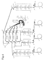
- Fig. 4 is a system diagram schematically showing a range of the rotary press and the paper threading apparatus for use in a first example of paper threading of the embodiment.
- the same apparatus, members and paper threading guides as in Fig. 1 are shown by the same reference numerals and characters.
- Fig. 5 is a system diagram schematically showing a range of a rotary press and a paper threading apparatus for use in another paper threading in a second example of paper threading of the embodiment.
- the same apparatus, members and paper threading guides as in Fig. 1 are assigned with the same reference numerals and characters.
- Fig. 6 is a view showing a part of a paper threading guide A(B) of the paper threading apparatus, a paper threading member drive unit U(V), and a paper threading member a(b) including a paper threading belt ab and an attachment part at fitted to its leading end portion of the embodiment.
- Arrow FF in Fig. 6 shows the direction in which the paper threading member a(b) moves in a paper threading direction.
- the printing unit T1 includes paper drawing rollers RD1, and TD1 (two in the embodiment shown in the drawing) which belong to the printing unit T1.
- the printing unit T4 includes paper drawing rollers RD4, and TD4 (two in the embodiment shown in the drawing) which belong to the printing unit T4.
- the printing unit T2 includes a paper drawing roller RD2 which belongs to the printing unit T2.
- the printing unit T3 includes a paper drawing roller RD3 which belongs to the printing unit T3.
- paper drawing rollers FD1 (two in the embodiment shown in the drawing) which guide the paper web into the folding unit F1 are provided in the vicinity of an upstream side in the paper threading direction of the folding unit F1.
- the respective printing units T1 to T4 have drive units TM1 to TM4 capable of driving at least printing cylinders respectively independently from the other printing units, and the folding unit F1 has a drive unit FM1 drivable independently from the respective printing units (refer to Fig. 3 ).
- the respective paper drawing rollers RD1 to RD4, TD1, TD4 and FD1 have individual drive units RDM1 to RDM4, TDM1, TDM4 and FDM1 shown in Fig. 3 .
- the printing cylinders of the respective printing units T1 to T4, and the respective paper drawing rollers RD1 to RD4, TD1 and TD4 which belong to the respective printing units T1 to T4 can be driven and stopped independently from one another, and can be driven and stopped individually with respect to the fold unit F1 and the paper drawing roller FD1.
- the fold unit F1 and the paper drawing roller FD1 can be driven and stopped independently from each other, and a so-called drive mode without a shaft is carried out.
- the rotary press includes the paper threading apparatus which has paper threading guides A1 to A5 placed in the regions from the respective paper supply units R1 to R4 to the folding unit F1, and paper threading guides B1 to B5 placed in the regions from the vicinity of the downstream sides of the respective slitter devices C1 to C5 to the folding unit F1, and includes at least the same configuration and function as described in the above described Description of the Related Art.
- Y denotes branched portions and merging portions (paper threading guide branched portions/merging portions) which are disposed at proper locations of the paper threading guides of the paper threading apparatus and change the paper threading paths.
- Paper supply unit limit switches L1 to L4 which detect arrival of the attachment part at of the paper threading member a shown in Fig. 6 are mounted to end portions at the respective paper supply unit sides, of the paper threading guides A1 to A4. Further, cutting unit side limit switches L30 to L34 which detect arrival of the attachment part at of a paper threading member b shown in Fig. 6 are mounted to end portions at the respective cutting unit sides, of the paper threading guides B1 to B5.
- folding unit limit switches L10 to L19 which detect arrival of the attachment part at of the paper threading member a or b are mounted to end portions at the folding unit side, of the paper threading guides A1 to A5 and B1 to B5.
- H denotes a housing case (paper threading belt housing container) which houses the paper threading belt ab of the paper threading member a or b.
- waiting position limit switches L20 to L29 which detect arrival of the attachment part at of the paper threading member a or b are provided in spots in the middle of the two paper drawing rollers FD1 and FD1, which are in the regions in the vicinity of the upstream side in the paper threading direction of the folding unit F1, of the respective paper threading guides A1 to A5 and B1 to B5.
- a paper threading control unit 1 included by the paper threading apparatus of the rotary press in the embodiment includes a paper threading path determining unit 11, a processing unit 12 and a drive signal transmitting unit 13 as shown in Fig. 3 .
- the paper threading control unit 1 is connected to a paper threading pattern designating unit 2, a paper threading start signal unit (switch) 3 and the respective paper threading member drive units U1 to U5 and V1 to V5 which are included by the paper threading apparatus, the printing cylinder drive units TM1 to TM4 of the printing units T1 to T4, the paper drawing roller drive units RDM1 to RDM4, TDM1 and TDM4 of the paper drawing rollers RD1 to RD4, TD1 and TD4 which belong to these printing units, the waiting position limit switches L20 to L29 and the folding unit limit switches L10 to L19, and the automatic attaching units P1 to P5.
- the paper threading path determining unit 11 determines the paper webs W1 to W4 for which printing is to be performed, namely, the paper supply units R1 to R4, the printing units T1 to T4 which perform printing, and the paper threading path for threading each of the paper webs W1 to W4 from each of the paper supply units R1 to R4 through any of the printing units T1 to T4 to the folding unit F1, as the paper webs W1 to W4, the printing units T1 to T4 and the paper threading guides A1 to A4 of the paper threading path shown by the thick solid line as shown in, for example, Figs. 1 and 4 .
- the paper threading path determining unit 11 can conduct driving and stopping control of the paper threading member drive units U1 to U4 provided in the paper threading guides A1 to A4 installed along the determined paper threading path, the printing cylinder drive units TM1 to TM4 of the printing units T1 to T4 on the paper threading path, and the paper drawing roller drive units RDM1 to RDM4, TDM1 and TDM4 of the paper drawing rollers RD1 to RD4, TD1 and TD4 which belong to the printing units, at the same time for each paper threading path, and combines them as sets.
- the processing unit 12 receives and stores the set information combined by the paper threading path determining unit 11, and receives a paper threading start signal from the paper threading start signal unit (switch) 3, respective detection signals from the waiting position limit switches L20 to L29 and the folding unit limit switches L10 to L19, and starting signals of automatic attaching units P1 to P5 outputted based on the detection signals of detection unit not shown as will be described later, processes each of the signals with reference to the stored set information, and outputs a signal output command corresponding to the processing result to the drive signal transmitting unit 13.
- the drive signal transmitting unit 13 Based on a signal output command from the processing unit 12, the drive signal transmitting unit 13 outputs operation signals or stop signals to the above described respective drive units, that is, the respective paper threading member drive units U1 to U5 and V1 to V5, the printing cylinder drive units TM1 to TM4, and the paper drawing roller drive units RDM1 to RDM4, TDM1 and TDM4.
- the paper threading pattern designating unit 2 designates a paper threading pattern based on the printing specification(paper threading pattern designating step).
- the paper threading guides installed along the determined paper threading paths are the paper threading guides A1 to A4
- the end portions in the traveling direction of the paper webs W1 to W4 are attached to the attachments at of the respective paper threading members a1 to a4 which are caused to wait at the end portions at the paper supply unit side of the paper threading guides A1 to A4, in the paper supply units R1 to R4 (paper threading preparing step).
- a1, a2, a3 and a4 are the paper threading members a corresponding to the paper threading guides A1, A2, A3 and A4, respectively.
- the paper threading start signal unit (switch) 3 inputs a paper threading start signal into the paper threading control unit 1.
- the paper web is designated in advance with a paper threading start path designating function of the paper threading start signal unit (switch) 3.
- the corresponding paper supply unit is designated out of the paper supply units R1 to R4, and the paper web of the designated paper supply unit is designated in the embodiment.
- the designation is not limited to this, and the printing unit or the paper threading path in which the paper web to be threaded is threaded may be configured to be able to be designated.
- paper threading in the situation in which all the paper supply units R1 to R4 are designated so as to start paper threading of all the paper webs W1 to W4 at the same time will be described.
- the paper threading control unit 1 in which a paper threading start signal is inputted determines the paper threading path, and notifies the processing unit 12 of the paper threading path.
- the processing unit 12 confirms that the paper webs designated to be threaded are the paper webs W1 to W4, and confirms the paper threading paths through which the respective paper webs W1 to W4 are threaded, the printing units T1 to T4 corresponding to the paper threading paths and the paper threading guides A1 to A4.
- the paper threading control unit 1 further instructs the drive signal transmitting unit 13 to transmit an operation signal to each of combination sets of the respective paper threading member drive units U1 to U4 of the paper threading guides A1 to A4 along the above described paper threading paths, the printing cylinder drive units TM1 to TM4 of the printing units T1 to T4, and the paper drawing roller drive units RDM1 to RDM4, TDM1 and TDM4 of the paper drawing rollers RD1 to RD4, TD1 and TD4 which belong to these printing units.
- the processing unit 12 confirms that the wait position limit switches corresponding to the respective paper threading guides A1 to A4 are L20, L22, L26 and L28, and that the folding unit limit switches are L10, L12, L16 and L18, and forms the state of waiting the output signals of the limit switches.
- the drive signal transmitting unit 13 which is instructed to transmit the operation signal by the processing unit 12 transmits a drive signal to the above described respective drive units included in each set so that they are operated at the same time.
- the paper threading member drive unit U1 of the paper threading guide A1 is actuated, and starts to move the paper threading member a1 toward the fold unit F1.
- the printing cylinder drive unit TM1 of the printing unit T1 corresponding to the paper threading guide A1, and the paper drawing roller drive units RDM1 and TDM1 of the paper drawing rollers RD1 and TD1 which belong to the printing unit T1 are actuated, and rotate the printing cylinder of the printing unit T1 and the paper drawing rollers RD1 and TD1 which belong to the printing unit T1 at substantially the same periphery speed as the moving speed of the paper threading member a1 so as not to interfere with the movement of the paper web W1 which is threaded by the above described paper threading member a1.
- the respective corresponding drive units are actuated when the drive signals are transmitted from the drive signal transmitting unit 13.
- the paper threading members a1 to a4 thread the end portions in the traveling direction of the paper webs W1 to W4 attached to the respective attachment parts at to the respective wait positions (first-stage paper threading step).
- the end portions in the traveling direction of the paper webs W1 to W4 move toward the respective wait positions.
- the lengths of the paper threading paths from the respective paper supply units R1 to R4 to the previously determined wait positions differ from one another, and in correspondence with this, the lengths of the paper threading guides A1 to A4 provided along the respective paper threading paths from the end portions at the paper supply unit sides of the respective paper supply units R1 to R4 to the wait position limit switches L20, L22, L26 and L28 differs from one another.
- the order of the lengths are in the relation of A1>A4>A2>A3.
- the wait position limit switch L26 detects the arrival of the attachment part at of the paper threading member a3 which moves along the paper threading guide A3 having the shortest length from the end portion at the paper supply unit to the wait position limit switch among the paper threading members a1 to a4.
- the shortest, the first that is, in the order of the paper threading guides A2, A4 and A1, the arrival at the previously determined wait position, of the attachment part at of the paper threading member a2 which moves along the paper threading guide A2 is detected by the wait position limit switch L28, the arrival at the previously determined wait position, of the attachment part at of the paper threading member a4 which moves along the paper threading guide A4 is detected by the wait position limit switch L22, and the arrival at the previously determined position, of the attachment part at of the paper threading member a1 which moves along the paper threading guide A1 is detected by the wait position limit switch L20.
- the wait position limit switch L26 When the wait position limit switch L26 detects the attachment part at of the paper threading member a3, the wait position limit switch L26 outputs a detection signal toward the processing unit 12 of the paper threading control unit 1.
- the processing unit 12 in which the detection signal of the wait position limit switch L26 is inputted instructs the drive signal transmitting unit 13 to transmit a stop signal to the corresponding set so as to stop each of the drive units of the above described set relating to the paper threading path corresponding to the paper threading guide A3 provided with the wait position limit switch L26 at the same time.
- the drive signal transmitting unit 13 to which the instruction is transmitted from the processing unit 12 transmits a signal for stopping each of the drive units of the above described set relating to the paper threading path corresponding to the paper threading guide A3 to each of the drive units included in this set, that is, the set relating to the paper threading path extending from the paper supply unit R3 to the folding unit F1.
- the wait position limit switch L28 detects the attachment part at of the paper threading member a2
- the wait position limit switch L28 outputs a detection signal toward the processing unit 12 of the paper threading control unit 1.
- the processing unit 12 in which the detection signal of the wait position limit switch L28 is inputted instructs the drive signal transmitting unit 13 to transmit a stop signal to the corresponding set so as to stop each of the drive units of the above described set relating to the paper threading path corresponding to the paper threading guide A2 provided with the wait position limit switch L28 at the same time.
- the drive signal transmitting unit 13 to which the instruction is transmitted from the processing unit 12 transmits a signal for stopping each of the drive units of the above described set relating to the paper threading path corresponding to the paper threading guide A2 to each of the drive units included in this set, that is, the set relating to the paper threading path extending from the paper supply unit R2 to the folding unit F1.
- the wait position limit switch L22 detects the attachment part at of the paper threading member a4
- the wait position limit switch L22 outputs a detection signal to the processing unit 12 of the paper threading control unit 1.
- the processing unit 12 in which the detection signal of the wait position limit switch L22 is inputted instructs the drive signal transmitting unit 13 to transmit a stop signal to the corresponding set so as to stop each of the drive units of the above described set relating to the paper threading path corresponding to the paper threading guide A4 provided with the wait position limit switch L22 at the same time.
- the drive signal transmitting unit 13 to which the instruction is transmitted from the processing unit 12 transmits a signal for stopping each of the drive units of the above described set relating to the paper threading path corresponding to the paper threading guide A4 to each of the drive units included in this set, that is, the set relating to the paper threading path extending from the paper supply unit R4 to the folding unit F1.
- the wait position limit switch L20 detects the attachment part at of the paper threading member a1
- the wait position limit switch L20 outputs a detection signal to the processing unit 12 of the paper threading control unit 1.
- the processing unit 12 in which the detection signal of the wait position limit switch L20 is inputted instructs the drive signal transmitting unit 13 to transmit a stop signal to the corresponding set so as to stop the respective drive units of the above described set relating to the paper threading path corresponding to the paper threading guide A1 provided with the wait position limit switch L20 at the same time.
- the drive signal transmitting unit 13 to which the instruction is transmitted from the processing unit 12 transmits a signal for stopping each of the drive units of the above described set relating to the paper threading path corresponding to the paper threading guide A1 to each of the drive units included in this set, that is, the set relating to the paper threading path extending from the paper supply unit R1 to the folding unit F1.
- each of the drive units included in the set relating to the paper threading path extending from the paper supply unit R3 to the folding unit F1 stops first to stop the movement of the paper threading member a3, and the attachment part at of the paper threading member a3 and the end portion in the traveling direction of the paper web W3 attached to the attachment part at are stopped in the state in which they arrive at the previously determined position to be brought into a waiting state.
- each drive unit included in the set relating to the paper threading path extending from the paper supply unit R2 to the folding unit F1 stops to stop the movement of the paper threading member a2, and the attachment part at of the paper threading member a2 and the end portion in the traveling direction of the paper web W2 attached to the attachment part at are stopped in the state in which they arrive at the previously determined position to be brought into a waiting state.
- Each drive unit included in the set relating to the paper threading path extending from the paper supply unit R4 to the folding unit F1 stops to stop the movement of the paper threading member a4, and the attachment part at of the paper threading member a4 and the end portion in the traveling direction of the paper web W4 attached to the attachment part at are stopped in the state in which they arrive at the previously determined position to be brought into a waiting state.
- Each drive unit included in the set relating to the paper threading path extending from the paper supply unit R1 to the folding unit F1 stops to stop the movement of the paper threading member a1, and the attachment part at of the paper threading member a1 and the end portion in the traveling direction of the paper web W1 attached to the attachment part at are stopped in the state in which they arrive at the previously determined position to be in a waiting state (stopping and waiting step).
- the processing unit 12 instructs the drive signal transmitting unit 13 to transmit an operation signal to each of the drive units included in all the sets corresponding to all the paper threading paths designated in the paper threading pattern designation, the drive unit FM1 of the folding unit F1, and the paper drawing roller drive unit FDM1 of the paper drawing rollers FD1 provided upstream in the vicinity of the folding unit F1, that is, the respective paper threading member drive units U1 to U4 of the paper threading guides A1
- the drive signal transmitting unit 13 which is instructed to transmit operation signals by the processing unit 12 transmits drive signals to the above described respective drive units so that the respective drive units operate at the same time.
- the above described respective drive units actuate when the drive signals are transmitted to the respective drive units from the drive signal transmitting unit 13.
- the paper threading members a1 to a4 with the end portions in the traveling direction of the paper webs W1 to W4 attached to the attachment parts at are moved toward the folding unit F1 which is the terminal end of the paper threading paths at the same time to thread the paper webs W1 to W4 to the folding unit F1 (latter-stage paper threading step).
- Arrival of the respective attachment parts at of the paper threading members a1 to a4 which have threaded the paper webs W1 to W4 to the folding unit F1 is detected by the folding unit limit switches L10, L12, L16 and L18 provided in the vicinity of the end portions at the folding unit side, of the respective paper threading guides A1 to A4, and the detection signals are inputted into the processing unit 12 of the paper threading control unit 1.
- the processing unit 12 in which the detection signal is inputted instructs the drive signal transmitting unit 13 to transmit a stop signal to the paper threading member drive unit of the paper threading guide provided with the folding unit limit switch which outputs the detection signal.
- the drive signal transmitting unit 13 which receives the instruction transmits a stop signal to the paper threading member drive unit of the paper threading guide provided with the folding unit limit switch which outputs the detection signal, and stops the operation of the paper threading member drive unit.
- the processing unit 12 instructs the drive signal transmitting unit 13 to transmit stop signals to all the above described printing cylinder drive units TM1 to TM4, and the paper drawing roller drive units RDM1 to RDM4 and TDM1 and TDM4 and the drive unit FM1 of the folding unit F1 and the paper drawing roller drive unit FDM1 of the paper drawing roller FD1 provided upstream in the vicinity of the folding unit F1.
- the drive signal transmitting unit 13 to which the instruction is transmitted from the processing unit 12 transmits stop signals to all the above described printing cylinder drive units TM1 to TM4 and the paper drawing roller drive units RDM1 to RDM4, TDM1 and TDM4 and the drive unit FM1 of the folding unit F1 and the paper drawing roller drive unit FDM1 of the paper drawing roller FD1 provided upstream in the vicinity of the folding unit F1, and stops all these drive units at the same time.
- the rotary press is actuated to actuate the printing cylinder drive units TM1 to TM4 of the printing units T1 to T4, the paper drawing roller drive units RDM1 to RDM4, TDM1 and TDM4 of the paper drawing rollers RD1 to RD4, TD1 and TD4 which belong to these printing units, the drive unit FM1 of the folding unit F1 and the paper drawing roller drive unit FDM1 of the paper drawing rollers FD1 provided upstream in the vicinity of the folding unit F1 to be operated together, and the paper webs W1 to W 4 are fed downward from the former E in the stacked state by an automatic unit not illustrated or the manual operation by an operator.
- the moving lengths of the above described paper threading members a1 to a4 at the time of the latter-stage paper threading step that is, the length of the paper threading guide A1 from the installation position of the wait position limit switch L20 to the installation position of the folding unit limit switch L10, the length of the paper threading guide A4 from the installation position of the wait position limit switch L22 to the installation position of the folding unit limit switch L12, the length of the paper threading guide A3 from the installation position of the wait position limit switch L26 to the installation position of the folding unit limit switch L16, and the length of the paper threading guide A2 from the installation position of the wait position limit switch L28 to the installation position of the folding unit limit switch L18 are substantially equal.
- the respective attachment parts at of the paper threading members a1 to a4 which are attached with the end portions in the traveling direction of the paper webs W1 to W4, arrive at the installation positions of the folding unit limit switches L10, L12, L16 and L18 substantially at the same time and are detected by these folding unit limit switches L10, L12, L16 and L18, and the folding unit limit switches L10, L12, L16 and L18 output detection signals substantially at the same time.
- stop of the respective paper threading member drive units U1 to U4 of the above described respective paper threading guides A1 to A4, and stop of all the printing cylinder drive units TM1 to TM4, the paper drawing roller drive units RDM1 to RDM4, TDM1 and TDM4, the drive unit FM1 of the folding unit F1 and the paper drawing roller drive unit FDM1 of the paper drawing roller FD1 provided upstream in the vicinity of the folding unit F1 are all performed substantially at the same time.
- the processing unit 12 of the above described paper threading control unit 1 may be configured to instruct the drive signal transmitting unit 13 to transmit operation signals to all the respective paper threading member drive units U1 to U4 of the paper threading guides A1 to A4 along the paper threading paths, the printing cylinder drive units TM1 to TM4 of the printing units T1 to T4, the paper drawing roller drive units RDM1 to RDM4, TDM1 and TDM4 of the paper drawing rollers RD1 to RD4, TD1 and TD4 which belong to these printing units, the drive unit FM1 of the folding unit F1 and the paper drawing roller drive unit FDM1 of the paper drawing roller FD1 provided upstream in the vicinity of the folding unit F1, at the same instant when all the detection signals outputted by the wait position limit switches L20, L22, L26 and L28 are inputted into the processing unit 12 (under the condition that all the detection signals are outputted).
- the paper threading path determining unit 11 determines the paper webs W1 to W4 for which printing is to be performed, that is, the paper supply units R1 to R4, the printing units T1 to T4 which perform printing, and the paper threading path for threading each of the paper webs W1 to W4 from each of the paper supply units R1 to R4 through any of the printing units T1 to T4 to the folding unit F1, as the paper webs W1 to W4, the printing units T1 to T4, the paper threading guides A1 to A4 of the paper threading paths shown by the thick solid line, and paper threading guides B1 to B4 of paper threading paths shown by the thick broken line as shown in, for example, Figs.
- the paper threading member drive unit U1 to U4. provided in the paper threading guides A1 to A4 installed along the above described determined paper threading paths
- paper threading member drive unit V1 to V4 provided in the paper threading guides B1 to B4
- the paper drawing roller drive unit RDM1 to RDM4, TDM1 and TDM4 of the paper drawing rollers RD1 to RD4, TD1 and TD4 which belong to these printing units can be controlled to be driven and stopped at the same time for each of the paper threading paths, and these are combined as sets.
- the paper threading pattern designating unit 2 designates a paper threading pattern based on the printing specification (paper threading pattern designating step).
- the paper webs which are determined to be used by designation of the paper threading pattern are, for example, the paper webs W1 to W4, and the paper threading guides installed along the determined paper threading paths are the paper threading guides A1 to A4 and other paper guides B1 to B4.
- the paper threading guides B1 to B4 are provided to the folding unit F1 through turn bars with portions in the vicinities of the downstream sides of slitter devices C1, C5, C4 and C2 that are cutting units which cut the paper webs parallel with the paper threading direction as end portions at the cutting unit sides.
- the respective paper webs W1 to W4 are cut parallel with the paper threading direction and split into two in the width direction during paper threading in the above described four paper threading paths by the slitter devices C1, C5, C4 and C2 provided in a rail frame unit S which is located in the four paper threading paths in which the paper threading guides A1 to A4 are installed and at a downstream side of the printing unit in the paper threading direction before the folding unit F1 to split each one of the paper webs W1 to W4 into two paper webs (half-width paper webs) W11 and W12, W21 and W22, W3 and W32, and W41 and W42 (not illustrated).
- the paper threading paths in which the other paper threading guides B1 to B4 are installed are the paper threading paths which extend to the folding unit after vertically overlaying half-width paper webs W12 to W42 which become free by the two-split by making the paper threading position in the direction orthogonal to the paper threading direction the same position as the half-width paper webs W11 to W41 which pass the paper threading paths in which the paper threading guides A1 to A4 are installed even after the two-split, by the turn-bars Z1, Z5, Z4 and Z2.
- the end portions in the traveling direction of the paper webs W1 to W4, which are determined to be subjected to paper threading by the above described designated paper threading pattern are attached to the attachment parts at of the respective paper threading members a1 to a4 which are caused to wait at the end portions at the paper supply unit sides, of the paper threading guides A1 to A4 (paper threading preparing step).
- the paper threading start signal unit (switch) 3 inputs a paper threading start signal into the paper threading control unit 1.
- the paper web is designated in advance with a paper threading start path designating function included in the paper threading start signal unit (switch) 3, which is the same as the above described first example of paper threading.
- the corresponding paper supply unit is designated from the paper supply units R1 to R4, and the paper web of the designated paper supply unit is designated in this embodiment.
- the designation is not limited to this, and the printing unit or the paper threading path starting from the paper supply unit, in which the paper web to be threaded is threaded, may be configured to be able to be designated.
- paper threading in the state in which all the paper supply units R1 to R4 are designated so as to thread all the paper webs W1 to W4 at the same time will be described.
- the processing unit 12 confirms that the paper webs designated to be threaded are the paper webs W1 to W4, and confirms the paper threading paths through which the respective paper webs W1 to W4 are threaded, the printing units T1 to T4 corresponding to the paper threading paths and the paper threading guides A1 to A4, B1 to B4, and automatic attaching units P1, P2, P4 and P5.
- the processing unit 12 instructs the drive signal transmitting unit 13 to transmit an operation signal to each combination set of the respective paper threading member drive units U1 to U4 of the paper threading guides A1 to A4 along the above described paper threading paths, the printing cylinder drive units TM1 to TM4 of the printing units T1 to T4, and the paper drawing roller drive units RDM1 to RDM4, TDM1 and TDM4 of the paper drawing rollers RD1 to RD4, TD1 and TD4 which belong to these printing units.
- the processing unit 12 confirms that the wait position limit switches corresponding to the respective paper threading guides A1 to A4 are L20, L28, L26 and L22, that wait position limit switches corresponding to the respective paper threading guides B1 to B4 are L21, L29, L27 and L23, that the folding unit limit switches corresponding to the respective paper threading guides A1 to A4 are L10, L12, L16 and L18, and that folding unit limit switches corresponding to the respective paper threading guides B1 to B4 are L11, L19, L17 and L13, and forms the state of waiting for the output signals of the limit switches.
- the processing unit 12 forms the state of waiting for actuation signals for actuating the automatic attaching units P1, P2, P4 and P5 which are outputted based on detection signals of detecting unit not illustrated as will be described later in order to attach end portions in the traveling directions of the half-width paper webs W12 to W42 to attachment parts at of paper threading members b1 to b4 in order that the other paper threading members b1 to b4 different from the paper threading members a1 to a4 which are caused to wait at the end portions at the cutting unit sides, of the respective paper threading guides B1 to B4 start paper threading.
- b1, b2, b3 and b4 denote paper threading members b corresponding to the paper threading guides B1, B2, B3 and B4, respectively.
- the drive signal transmitting unit 13 which is instructed to transmit the operation signal by the processing unit 12 transmits drive signals to the above described respective drive units included in each set so that they are operated at the same time.
- the paper threading member drive unit U1 of the paper threading guide A1 is actuated, and starts to move the paper threading member a1 toward the folding unit F1.
- the printing cylinder drive unit TM1 of the printing unit T1 corresponding to the paper threading guide A1, and the paper drawing roller drive unit RDM1 and TDM1 of the paper drawing rollers RD1 and TD1 which belong to the printing unit T1 actuate, and rotate the printing cylinder of the printing unit T1 and the paper drawing rollers RD1 and TD1 which belong to the printing unit T1 at substantially the same periphery speed as the moving speed of the above described paper threading member a1 so as not to interfere with the movement of the paper web W1 which is threaded by the above described paper threading member a1.
- the respective corresponding drive units are actuated when the drive signal is transmitted from the drive signal transmitting unit 13.
- the paper threading members a1 to a4 thread the end portions in the traveling directions of the paper webs W1 to W4 attached to the respective attachment parts at to the positions of the slitter devices C1, C5, C4 and C2 which are provided in the rail frame unit S in the paper threading paths respectively.
- Paper-threading at the downstream side from the slitter devices C1, C5, C4 and C2 of the respective paper webs W1 to W4 which arrive at the slitter devices C1, C5, C4 and C2 are performed as follows.
- the paper web W1 (W2, W3, W4) is split into two in the width direction parallel with the paper threading direction while being threaded along the paper threading guide A1 (A2, A3, A4) by passing the slitter device C1 (C5, C4, C2) provided in the rail frame unit S by the progress of paper threading, and one paper web W1 (W2, W3, W4) is split into two half-width paper webs W1 (W21, W31, W41) and W12 (W22, W32, W42).
- the half-width paper web W11 (W21, W31, W41) is attached to the attachment part at of the paper threading member a1 (a2, a3, a4) which moves along the paper threading guide A1 (A2, A3, A4), and is threaded to the wait position, as in the description of the above described first example of paper threading (however, the paper web W1 (W2, W3, W4) in the above described explanation is changed to the half-width paper web W11 (W21, W31, W41)) with the movement of the paper threading member a1 (a2, a3, a4).
- the end portion in the traveling direction approaches the automatic attaching unit P1 (P5, P4, P2) which is the nearest to the downstream side of the slitter device C1 (C5, C4, C2) with the movement of the above described paper threading member a1 (a2, a3, a4).
- a detecting unit not illustrated which detects the end portion outputs a detection signal, and by an actuation signal which is outputted based on this signal, the automatic attaching unit P1 (P5, P4, P2) is actuated.
- the processing unit 12 of the paper threading control unit 1 receives this actuation signal, and instructs the drive signal transmitting unit 3 to transmit an operation signal to a paper threading member drive unit V1 (V2, V3, V4) provided in a paper threading guide B1 (B2, B3, B4) which constitutes a set.
- the drive signal transmitting unit 13 which is instructed to transmit an operation signal by the processing unit 12 transmits a drive signal to the above described paper threading member drive unit V1 (V2, V3, V4) so that they are operated at the same time.
- the paper threading member drive unit V1 (V2, V3, V4) receives the above described drive signal and starts driving to move a paper threading member b1 (b2, b3, b4) waiting at the end portion at the cutting unit side of the paper threading guide B1 (B2, B3, B4) toward the folding unit.
- the automatic attaching unit P1 (P5, P4, P2) attaches the end portion in the traveling direction of the half-width paper web W12 (W22, W32, W42) to the attachment part at of the paper threading member b1 (b2, b3, b4) which moves at substantially the same speed as the moving speed of the half-width paper web W12 (W22, W32, W42).
- the paper web W1 (W2, W3, W4) is one piece up to the position of the slitter device C1 (C5, C4, C2), and from the position of the slitter device C1 (C5, C4, C2), the leading side is separated into the half-width paper web W11 (W21, W31, W41) and the half-width paper web W12 (W22, W32, W42).
- the end portions in the traveling directions of the respective half-width paper web W11 (W21, W31, W41) and the half-width paper web W12 (W22, W32, W42) move toward the previously determined wait positions respectively, that is, the position provided with the wait position limit switch L20 (L28, L26, L22) and the position provided with the wait position limit switch L21 (L29, L27, L23).
- the lengths of the paper threading paths of the half-width paper webs W11 to W41 from the paper supply units R1 to R4 to the previously determined wait positions through the positions of the slitter devices C1, C5, C4 and C2 differ from one another.
- the length of the paper threading guide A1 for threading the half-width paper web W11 is the longest
- the paper threading guide A4 for threading the half-width paper web W41 is the second longest
- the paper threading guide A2 for threading the half-width paper web W21 is the third longest
- the paper threading guide A3 for threading the half-width paper web W31 is the shortest.
- the wait position limit switch L26 When the wait position limit switch L26 detects the attachment part at of the paper threading member a3, the wait position limit switch L26 outputs a detection signal to the processing unit 12 of the paper threading control unit 1.
- the processing unit 12 in which the detection signal of the wait position limit switch L26 is inputted instructs the drive signal transmitting unit 13 to transmit a stop signal to the corresponding set so as to stop the respective drive units of the above described set relating to the paper threading path corresponding to the paper threading guide A3 provided with the wait position limit switch L26, that is, the paper threading member drive unit U3 provided in the paper threading guide A3, the printing cylinder drive unit TM3 of the printing unit T3, the paper drawing roller drive unit RDM3 which drives the paper drawing roller RD3 which belongs to the printing unit T3 and the paper threading member drive unit V3 provided in the paper threading guide B3, at the same time.
- the drive signal transmitting unit 13 to which the instruction is transmitted from the processing unit 12 transmits a signal for stopping each of the drive units of the above described set relating to the paper threading path corresponding to the paper threading guide A3 to each of the drive units included in this set, that is, the set relating to the paper threading path extending from the paper supply unit R3 to the folding unit F1.
- the above described respective drive units included in the set relating to the paper threading path extending from the paper supply unit R3 to the folding unit F1 stop to stop the movement of the paper threading members a3 and b3, and the attachment part at of the paper threading member a3 and the end portion in the traveling direction of the half-width paper web W31 attached to the attachment part at are stopped in the state in which they reach the previously determined position, and the attachment part at of the paper threading member b3 and the end portion in the traveling direction of the half-width paper web W32 attached to the attachment part at are stopped at the upstream side in the paper threading direction from the position of the wait position limit switch L27, which is a previously determined position, by the difference of the length of the paper threading guide A3 from the slitter device C4 to the wait position limit switch L26 and the length of the paper threading guide B3
- the wait position limit switch L28 When the wait position limit switch L28 detects the attachment part at of the paper threading member a2, the wait position limit switch L28 outputs a detection signal to the processing unit 12 of the paper threading control unit 1.
- the processing unit 12 in which the detection signal of the wait position limit switch L28 is inputted instructs the drive signal transmitting unit 13 to transmit a stop signal to the corresponding set so as to stop the respective drive units of the above described set relating to the paper threading path corresponding to the paper threading guide A2 provided with the wait position limit switch L28, that is, the paper threading member drive unit U2 provided in the paper threading guide A2, the printing cylinder drive unit TM2 of the printing unit T2, the paper drawing roller drive unit RDM2 which drives the paper drawing roller RD2 which belongs to the printing unit T2 and the paper threading member drive unit V2 provided in the paper threading guide B2, at the same time.
- the drive signal transmitting unit 13 to which the instruction is transmitted from the processing unit 12 transmits a signal for stopping the respective drive units of the above described set relating to the paper threading path corresponding to the paper threading guide A2 to the above described respective drive units included in this set, that is, the set relating to the paper threading path extending from the paper supply unit R2 to the folding unit F1.
- the wait position limit switch L22 detects the attachment part at of the paper threading member a4
- the wait position limit switch L22 outputs a detection signal to the processing unit 12 of the paper threading control unit 1.
- the processing unit 12 in which the detection signal of the wait position limit switch L22 is inputted instructs the drive signal transmitting unit 13 to transmit a stop signal to the corresponding set so as to stop the respective drive units of the above described set relating to the paper threading path corresponding to the paper threading guide A4 provided with the wait position limit switch L22, that is, the paper threading member drive unit U4 provided in the paper threading guide A4, the printing cylinder drive unit TM4 of the printing unit T4, the paper drawing roller drive units RDM4 and TDM4 which drive the paper drawing rollers RD4 and TD4 which belong to the printing unit T4 and the paper threading member drive unit V4 provided in the paper threading guide B4, at the same time.
- the drive signal transmitting unit 13 to which the instruction is transmitted from the processing unit 12 transmits a signal for stopping the respective drive units of the above described set relating to the paper threading path corresponding to the paper threading guide A4 to the above described respective drive units included in this set, that is, the set relating to the paper threading path extending from the paper supply unit R4 to the folding unit F1.
- the wait position limit switch L20 When the wait position limit switch L20 detects the attachment part at of the paper threading member a1, the wait position limit switch L20 outputs a detection signal to the processing unit 12 of the paper threading control unit 1.
- the processing unit 12 in which the detection signal of the wait position limit switch L20 is inputted instructs the drive signal transmitting unit 13 to transmit a stop signal to the corresponding set so as to stop the respective drive unit of the above described set relating to the paper threading path corresponding to the paper threading guide A1 provided with the wait position limit switch L20, that is, the paper threading member drive unit U1 provided in the paper threading guide A1, the printing cylinder drive unit TM1 of the printing unit T1, the paper drawing roller drive units RDM1 and TDM1 which drive the paper drawing rollers RD1 and TD1 which belong to the printing unit T1 and the paper threading member drive unit V1 provided in the paper threading guide B1, at the same time.
- the drive signal transmitting unit 13 to which the instruction is transmitted from the processing unit 12 transmits a signal for stopping the respective drive units of the above described set relating to the paper threading path corresponding to the paper threading guide A1 to the above described respective drive units included in this set, that is, the set relating to the paper threading path extending from the paper supply unit R1 to the folding unit F1.
- the paper threading members a2 and b2, a4 and b4 and a1 and b1 are stopped, and the respective attachment parts at of the paper threading members a2, a4 and a1 and the end portions in the traveling directions of the half-width paper webs W21, W41 and W11 attached to the respective attachment parts at are stopped in the state in which they arrive at the previously determined positions.
- the respective attachment parts at of the paper threading members b2, b4 and b1 and the end portions in the traveling directions of the half-width paper webs W22, W42 and W12 which are attached to the respective attachment parts at are stopped at the upstream side from the previously determined positions. All of them are respectively in the waiting state (stopping and waiting step).
- the stop position of the attachment part at of the paper threading member b2 and the end portion in the traveling direction of the half-width paper web W22 attached to the attachment part at is in the position at the upstream side in the paper threading direction by the difference of the length of the paper threading guide A2 from the slitter device C5 to the wait position limit switch L28 and the length from the end portion at the cutting unit side, of the paper threading guide B2 to the wait position limit switch L29.
- the stop position of the attachment part at of the paper threading member b4 and the end portion in the traveling direction of the half-width paper web W42 attached to the attachment part at is in the position at the upstream side in the paper threading direction by the difference of the length of the paper threading guide A4 from the slitter device C2 to the wait position limit switch L22 and the length from the end portion at the cutting unit side, of the paper threading guide B4 to the wait position limit switch L23.
- the stop position of the attachment part at of the paper threading member b1 and the end portion in the traveling direction of the half-width paper web W12 attached to the attachment part at is in the position at the upstream side in the paper threading direction by the difference of the length of the paper threading guide A1 from the slitter device C1 to the wait position limit switch L20 and the length from the end portion at the cutting unit side, of the paper threading guide B1 to the wait position limit switch L21.
- the lengths of the paper threading guides B1 to B4 from the end portions at the cutting unit sides to the wait position limit switches L21, L29, L27 and L23 are longer than the lengths of the paper threading guides A1 to A4 from the slitter devices C1, C5, C4 and C2 to the wait position limit switches L20, L28, L26 and L22.
- the length of the paper threading guide B1 from the end portion at the cutting unit side to the wait position limit switch L21 is set to be shorter than the length of the paper threading guide A1 from the slitter device C1 to the wait position limit switch L20
- arrival of the attachment part at of the paper threading member b1 which moves along the paper threading guide B1 at the previously determined wait position is detected first by the wait position limit switch L21 in the first-stage paper threading.
- the stopping and waiting step in the paper threading path extending from the above described paper supply unit R1 to the folding unit F1 is carried out based on the detection signal of the wait position limit switch L21 by the detection.
- the wait position limit switch L21 when detecting the attachment part at of the paper threading member b1, the wait position limit switch L21 outputs a detection signal to the processing unit 12 of the paper threading control unit 1.
- the processing unit 12 in which the detection signal of the wait position limit switch L21 is inputted instructs the drive signal transmitting unit 13 to transmit a stop signal to the set so as to stop the respective drive units of the above described set relating to the paper threading path corresponding to the paper threading guide A1 of the same set as the paper threading guide B1 provided with the wait position limit switch L21, that is, the printing cylinder drive unit TM1, the paper drawing roller drive units RDM1 and TDM1, and the paper threading member drive units U1 and V1 at the same time.
- the drive signal transmitting unit 13 to which the instruction is transmitted from the processing unit 12 transmits a signal for stopping the above described respective drive units of the above described set relating to the paper threading path corresponding to the paper threading guide A1 to the respective drive units included in this set.
- the above described respective drive units included in the set relating to the paper threading path extending from the paper supply unit R1 to the folding unit F1 is stopped first to stop the movement of the paper threading members a1 and b1, and the attachment part at of the paper threading member b1 and the end portion in the traveling direction of the half-width paper web W31 attached to the attachment part at are stopped in the state in which they arrive at the previously determined position.
- each of the paper webs W1 to W4 which are fed out of each of the paper supply units R1 to R4 and threaded along the paper threading paths previously determined by the paper threading path determining unit 11 of the paper threading control unit 1, when either one of two half-width paper webs divided into two by each of the slitter devices C1, C5, C4 and C2 arrives at the previously determined wait position, each of the paper webs W1 to W4 finishes paper threading and is brought into a stopping and waiting state.
- the drive signal transmitting unit 13 which is instructed to transmit operation signals by the processing unit 12 transmits the drive signals to the above described respective drive units so that they are operated at the same time.
- the above described respective drive unit are actuated when the drive signals are transmitted to them from the drive signal transmitting unit 13.
- the paper threading members a1 to a4 in which the end portions in the traveling direction of the half-width paper webs W11 to W14 are attached to the attachment parts at, and the paper threading members b1 to b4 in which the end portions in the traveling direction of the half-width paper webs W12 to W42 are attached to the attachment parts at are moved toward the folding unit F1 which is the terminal end of the paper threading paths at the same time to thread the half-width paper webs W11 to W41 and W12 to W42, that is, the paper webs W1 to W4 to the folding unit F1 (latter-stage paper threading step).
- arrival of the respective attachment parts at of the paper threading members a1 to a4 which have threaded the half-width paper webs W11 to W41 to the folding unit F1 is detected by the folding unit limit switches L10, L18, L16 and L12 provided in the vicinity of the end portions at the folding unit side, of the respective paper threading guides A1 to A4, and the detection signals are inputted into the processing unit 12 of the threading control unit 1.
- the processing unit 12 in which the detection signal is inputted instructs the drive signal transmitting unit 13 to transmit a stop signal to the paper threading member drive unit of the paper threading guide provided with the folding unit limit switch which outputs the detection signal, that is, the corresponding paper threading guide among the paper threading guides A1 to A4.
- the drive signal transmitting unit 13 which receives the instruction transmits a stop signal to the paper threading member drive unit of the paper threading guide provided with the folding unit limit switch which outputs the detection signal, that is, the corresponding paper threading guide among the paper threading guides A1 to A4, and stops the operation of the paper threading member drive unit.
- the arrival of the paper threading members b1 to b4 attached with the half-width paper webs W12 to W42 is detected by the folding unit limit switches L11, L19, L17 and L13 which are provided in the vicinity of the end portions at the folding unit side by being delayed by the time required for moving the difference of the length of the respective paper threading guides A1 to A4 from the slitter devices C1, C5, C4 and C2 to the wait position limit switches L20, L28, L26 and L22, and the length of the paper threading guides B1 to B4 from the end portions at the cutting unit side to the wait position limit switches L21, L29, L27 and L23, and the detection signals are inputted into the processing unit 12 of the paper threading control unit 1.
- the processing unit 12 in which the detection signal is inputted instructs the drive signal transmitting unit 13 to transmit a stop signal to the paper threading member drive unit of the paper threading guide provided with the folding unit limit switch which outputs the detection signal, that is, the corresponding paper threading guide among the paper threading guides B1 to B4.
- the drive signal transmitting unit 13 which receives the instruction transmits a stop signal to the paper threading member drive unit of the paper threading guide provided with the folding unit limit switch which outputs the detection signal, that is, the corresponding paper threading guide among the paper threading guides B1 to B4, and stops the operation of the paper threading member drive unit.
- the paper threading member which moves along the paper threading guide corresponding to the folding unit limit switch which outputs the detection signal stops in a state in which its attachment part at is located at the position corresponding to the installation position of the folding unit limit switch of the paper threading guide, and the paper threading belt ab is housed in the paper threading belt housing container H.
- the half-width paper webs W11 to W41 which finishes paper threading ahead are integral with the half-width paper webs W12 to W42 at the upstream side from the slitter devices C1, C5, C4 and C2, and therefore, are fed into the folding unit F1 side until termination of paper threading of the half-width paper webs W12 to W42, which is later than that of the half-width paper webs W11 to W41.
- the half-width paper webs W11 to W41 is drawn in and wound up with the known technique of winding paper webs (for example, the web winding device disclosed in Japanese Patent Laid-Open No. 10-297802 (reference publication 2)) or a manual operation until termination paper threading of the half-width paper webs W12 to W42.
- the processing unit 12 instructs the drive signal transmitting unit 13 to transmit stop signals to all the above described printing cylinder drive units TM1 to TM4, and the paper drawing roller drive units RDM1 to RDM4, TDM1 and TDM4 and the drive unit FM1 of the folding unit F1 and the paper drawing roller drive unit FDM1 of the paper drawing rollers FD1 provided upstream in the vicinity of the folding unit F1.
- the drive signal transmitting unit 13 to which the instruction is transmitted from the processing unit 12 transmits stop signals to all the above described printing cylinder drive units TM1 to TM4 and the paper drawing roller drive units RDM1 to RDM4, TDM1 and TDM4 and the drive unit FM1 of the folding unit F1 and the paper drawing roller drive unit FDM1 of the paper drawing roller FD1 provided upstream in the vicinity of the folding unit F1, and stops all these drive units at the same time.
- the instruction to the drive signal transmitting unit 13 from the processing unit 12 of the above described paper threading control unit 1 on the occasion of the start of the latter-stage paper threading step may be configured to be conducted at the same time when all the detection signals which are outputted by any one of a set of the wait position limit switches L20 and L21, any one of a set of L22 and L23, any one of a set of L26 and L27 and any one of a set of L28 and L29 which belong the same sets of the wait position limit switches are inputted into the processing unit 12 of the above described paper threading control unit 1, instead of the operation of the above described paper threading start signal unit (switch) 3.
- the paper threading member drive unit, the printing units and the paper drawing rollers are operated together, or driven and stopped at the same time, and this includes a proper time difference, for example, about one second in view of the time required for driving and stopping the paper threading members, the printing cylinders of the printing units and the paper drawing rollers, the response time to the outputted signals and the like.
- the installation positions of the wait position limit switches L20 to L29 are not limited to those of this embodiment.
Landscapes
- Engineering & Computer Science (AREA)
- Mechanical Engineering (AREA)
- Replacement Of Web Rolls (AREA)
- Rotary Presses (AREA)
- Folding Of Thin Sheet-Like Materials, Special Discharging Devices, And Others (AREA)
Applications Claiming Priority (1)
| Application Number | Priority Date | Filing Date | Title |
|---|---|---|---|
| JP2007128715A JP4317240B2 (ja) | 2007-05-15 | 2007-05-15 | 輪転機の紙通し方法及び輪転機の紙通し装置 |
Publications (2)
| Publication Number | Publication Date |
|---|---|
| EP1992484A2 true EP1992484A2 (de) | 2008-11-19 |
| EP1992484A3 EP1992484A3 (de) | 2009-10-21 |
Family
ID=39712466
Family Applications (1)
| Application Number | Title | Priority Date | Filing Date |
|---|---|---|---|
| EP08152849A Withdrawn EP1992484A3 (de) | 2007-05-15 | 2008-03-17 | Verfahren und Vorrichtung zum Einführen von Papierbahnen für eine Rotationsdruckmaschine |
Country Status (2)
| Country | Link |
|---|---|
| EP (1) | EP1992484A3 (de) |
| JP (1) | JP4317240B2 (de) |
Cited By (1)
| Publication number | Priority date | Publication date | Assignee | Title |
|---|---|---|---|---|
| IT202100018821A1 (it) * | 2021-07-15 | 2023-01-15 | Ytd S R L | Svolgitore automatico di materiali flessibili avvolti su bobine e procedimento per alimentare una macchina operatrice con detti materiali flessibili |
Families Citing this family (1)
| Publication number | Priority date | Publication date | Assignee | Title |
|---|---|---|---|---|
| CN111016422B (zh) * | 2019-12-13 | 2021-07-30 | 株洲三新包装技术有限公司 | 瓦楞纸板印刷机吸盘式送纸系统及方法 |
Citations (4)
| Publication number | Priority date | Publication date | Assignee | Title |
|---|---|---|---|---|
| JPH03162353A (ja) | 1989-11-21 | 1991-07-12 | Tokyo Kikai Seisakusho Ltd | 輪転機の紙通し装置 |
| JPH05269963A (ja) | 1992-03-25 | 1993-10-19 | Tokyo Kikai Seisakusho Ltd | 輪転機における自動紙通し制御装置 |
| JPH079673A (ja) | 1993-06-02 | 1995-01-13 | Man Roland Druckmas Ag | 印刷機械に材料ロールを引き込む引き込み装置およびその方法 |
| JPH10297802A (ja) | 1997-04-30 | 1998-11-10 | Mitsubishi Heavy Ind Ltd | 輪転機の紙通し装置 |
-
2007
- 2007-05-15 JP JP2007128715A patent/JP4317240B2/ja active Active
-
2008
- 2008-03-17 EP EP08152849A patent/EP1992484A3/de not_active Withdrawn
Patent Citations (4)
| Publication number | Priority date | Publication date | Assignee | Title |
|---|---|---|---|---|
| JPH03162353A (ja) | 1989-11-21 | 1991-07-12 | Tokyo Kikai Seisakusho Ltd | 輪転機の紙通し装置 |
| JPH05269963A (ja) | 1992-03-25 | 1993-10-19 | Tokyo Kikai Seisakusho Ltd | 輪転機における自動紙通し制御装置 |
| JPH079673A (ja) | 1993-06-02 | 1995-01-13 | Man Roland Druckmas Ag | 印刷機械に材料ロールを引き込む引き込み装置およびその方法 |
| JPH10297802A (ja) | 1997-04-30 | 1998-11-10 | Mitsubishi Heavy Ind Ltd | 輪転機の紙通し装置 |
Cited By (3)
| Publication number | Priority date | Publication date | Assignee | Title |
|---|---|---|---|---|
| IT202100018821A1 (it) * | 2021-07-15 | 2023-01-15 | Ytd S R L | Svolgitore automatico di materiali flessibili avvolti su bobine e procedimento per alimentare una macchina operatrice con detti materiali flessibili |
| WO2023286022A1 (en) * | 2021-07-15 | 2023-01-19 | YTD S.r.l. | Automatic unwinder of flexible materials wound on reels and process for feeding an operating machine with said flexible materials |
| US12486133B2 (en) | 2021-07-15 | 2025-12-02 | Nicola FRIGO | Automatic unwinder of flexible materials wound on reels and process for feeding an operating machine with said flexible materials |
Also Published As
| Publication number | Publication date |
|---|---|
| JP4317240B2 (ja) | 2009-08-19 |
| JP2008285237A (ja) | 2008-11-27 |
| EP1992484A3 (de) | 2009-10-21 |
Similar Documents
| Publication | Publication Date | Title |
|---|---|---|
| US5542350A (en) | Draw-in device and process for feeding webs of material into a printing machine | |
| EP0418903B1 (de) | Papierbahneinführungsvorrichtung für Rotationsdruckmaschine | |
| EP1555570B1 (de) | Bindevorrichtung,Papierverarbeitungsvorrichtung und Bildformungssystem | |
| EP1061027B1 (de) | Papierbahnzuführvorrichtung in einer Rollenrotationsdruckmaschine mit einer Bahnspannungsregeleinrichtung | |
| JP5133402B2 (ja) | 新聞製作システム及び新聞の製作方法 | |
| US8302949B2 (en) | Apparatus and method for producing book blocks | |
| US8100053B2 (en) | Method for manufacturing bound printed products such as books, journals, magazines and the like, performed at least partially dependent on a working cycle | |
| US20080099974A1 (en) | Sheet processing apparatus and image forming apparatus including the same | |
| CN102482043A (zh) | 用于供给用于自动包装机的具有印刷位置标记的片状材料、尤其但是不排他的印刷塑料膜的卷筒的单元和方法 | |
| JP5000949B2 (ja) | シート処理装置及び画像形成装置 | |
| EP1992484A2 (de) | Verfahren und Vorrichtung zum Einführen von Papierbahnen für eine Rotationsdruckmaschine | |
| CN100445092C (zh) | 横向裁切卷筒纸的方法 | |
| US5628718A (en) | Method of operating a folder | |
| CN102325658A (zh) | 具有完全机器设置的卷筒纸印刷机 | |
| US7162954B1 (en) | Determination of cutting positions of web strands in a rotary printing press | |
| US11505420B2 (en) | High speed digital printing system and method for continuous web | |
| JP5918917B1 (ja) | オフセット輪転印刷機及びオフセット輪転印刷機の印刷制御方法 | |
| CA2655253A1 (en) | Method and apparatus for the treatment of a running material web | |
| JP4865493B2 (ja) | 印刷機およびその運転方法 | |
| GB2263437A (en) | Web handling between printing press and dryer. | |
| US6428458B2 (en) | Method of adjusting a longitudinal folding device in a folder of a web-fed printing machine | |
| CN100377876C (zh) | 印刷机 | |
| JP5234714B2 (ja) | 印刷機 | |
| EP4059729B1 (de) | Bilderzeugungsvorrichtung und bilderzeugungssystem | |
| US20230322002A1 (en) | Cutter and method of separation for sheets printed from a continuous web susceptible of longitudinal divisions and relative web |
Legal Events
| Date | Code | Title | Description |
|---|---|---|---|
| PUAI | Public reference made under article 153(3) epc to a published international application that has entered the european phase |
Free format text: ORIGINAL CODE: 0009012 |
|
| AK | Designated contracting states |
Kind code of ref document: A2 Designated state(s): AT BE BG CH CY CZ DE DK EE ES FI FR GB GR HR HU IE IS IT LI LT LU LV MC MT NL NO PL PT RO SE SI SK TR |
|
| AX | Request for extension of the european patent |
Extension state: AL BA MK RS |
|
| PUAL | Search report despatched |
Free format text: ORIGINAL CODE: 0009013 |
|
| AK | Designated contracting states |
Kind code of ref document: A3 Designated state(s): AT BE BG CH CY CZ DE DK EE ES FI FR GB GR HR HU IE IS IT LI LT LU LV MC MT NL NO PL PT RO SE SI SK TR |
|
| AX | Request for extension of the european patent |
Extension state: AL BA MK RS |
|
| RIC1 | Information provided on ipc code assigned before grant |
Ipc: B65H 20/16 20060101ALI20090915BHEP Ipc: B41F 13/03 20060101AFI20080908BHEP |
|
| 17P | Request for examination filed |
Effective date: 20100119 |
|
| AKX | Designation fees paid |
Designated state(s): DE |
|
| STAA | Information on the status of an ep patent application or granted ep patent |
Free format text: STATUS: THE APPLICATION IS DEEMED TO BE WITHDRAWN |
|
| 18D | Application deemed to be withdrawn |
Effective date: 20111001 |