EP0627205B1 - Support pour la cheville - Google Patents
Support pour la cheville Download PDFInfo
- Publication number
- EP0627205B1 EP0627205B1 EP94107110A EP94107110A EP0627205B1 EP 0627205 B1 EP0627205 B1 EP 0627205B1 EP 94107110 A EP94107110 A EP 94107110A EP 94107110 A EP94107110 A EP 94107110A EP 0627205 B1 EP0627205 B1 EP 0627205B1
- Authority
- EP
- European Patent Office
- Prior art keywords
- ankle
- foot
- web
- splint
- velcro
- Prior art date
- Legal status (The legal status is an assumption and is not a legal conclusion. Google has not performed a legal analysis and makes no representation as to the accuracy of the status listed.)
- Expired - Lifetime
Links
Images

Classifications
-
- A—HUMAN NECESSITIES
- A61—MEDICAL OR VETERINARY SCIENCE; HYGIENE
- A61F—FILTERS IMPLANTABLE INTO BLOOD VESSELS; PROSTHESES; DEVICES PROVIDING PATENCY TO, OR PREVENTING COLLAPSING OF, TUBULAR STRUCTURES OF THE BODY, e.g. STENTS; ORTHOPAEDIC, NURSING OR CONTRACEPTIVE DEVICES; FOMENTATION; TREATMENT OR PROTECTION OF EYES OR EARS; BANDAGES, DRESSINGS OR ABSORBENT PADS; FIRST-AID KITS
- A61F5/00—Orthopaedic methods or devices for non-surgical treatment of bones or joints; Nursing devices; Anti-rape devices
- A61F5/01—Orthopaedic devices, e.g. splints, casts or braces
- A61F5/0102—Orthopaedic devices, e.g. splints, casts or braces specially adapted for correcting deformities of the limbs or for supporting them; Ortheses, e.g. with articulations
- A61F5/0104—Orthopaedic devices, e.g. splints, casts or braces specially adapted for correcting deformities of the limbs or for supporting them; Ortheses, e.g. with articulations without articulation
- A61F5/0111—Orthopaedic devices, e.g. splints, casts or braces specially adapted for correcting deformities of the limbs or for supporting them; Ortheses, e.g. with articulations without articulation for the feet or ankles
-
- A—HUMAN NECESSITIES
- A61—MEDICAL OR VETERINARY SCIENCE; HYGIENE
- A61F—FILTERS IMPLANTABLE INTO BLOOD VESSELS; PROSTHESES; DEVICES PROVIDING PATENCY TO, OR PREVENTING COLLAPSING OF, TUBULAR STRUCTURES OF THE BODY, e.g. STENTS; ORTHOPAEDIC, NURSING OR CONTRACEPTIVE DEVICES; FOMENTATION; TREATMENT OR PROTECTION OF EYES OR EARS; BANDAGES, DRESSINGS OR ABSORBENT PADS; FIRST-AID KITS
- A61F13/00—Bandages or dressings; Absorbent pads
- A61F13/06—Bandages or dressings; Absorbent pads specially adapted for feet or legs; Corn-pads; Corn-rings
- A61F13/064—Bandages or dressings; Absorbent pads specially adapted for feet or legs; Corn-pads; Corn-rings for feet
- A61F13/066—Bandages or dressings; Absorbent pads specially adapted for feet or legs; Corn-pads; Corn-rings for feet for the ankle
Definitions
- the invention relates to an ankle orthosis, in particular for the early functional treatment fresher fibular ligament ruptures and severe tarsal distortions, consisting of a U-shaped joint cuff with a web running below the foot a flexible material, the orthosis made of a Articulated cuff with an outer ankle splint and one Inner ankle splint consists of the two ankle splint by one running under the heel of the foot Bridge and on the back under recess the heel and the Achilles tendon insertion through a wide band as well as on the front in its upper Area by at least one variable in length Webbing are connected and anatomically have adapted and shaped depressions, and from one across the sole of the foot proximal to the head of the Metatarsal I-V trending metatarsal, which encompass the lateral and medial margins and the Connection for two cross straps and a cross strap form and is connected via the cross belt.
- Such an ankle orthosis is from the in the preamble considered WO 89/10731 known.
- the at this ankle brace used cross straps are elastic and are only for one good fixation of the ankle orthosis to the foot; however, they leave inversion and eversion movements of the foot too.
- US-A 4,345,590 discloses a support bandage in which at least three elongated parts with one on the sole of the foot attached part are connected, of which three elongated parts a first part firmly attached to the Inside of the foot, a second part firmly on the Outside of the foot and a third part firmly on the Back of the leg is attached, taking all three Parts attached to the leg are attached to this Way to prevent sprains of the ankle and around to protect the ankle.
- This bandage consists of a flexible material and should only be a media or prevent lateral angling of the ankle. To achieve this, the bandage consists of a Heel section and a forefoot section that just over a web are connected. The forefoot part only serves to fix the bandage on the foot and is not restrictive on the movement of the ankle.
- DE-A-38 40 714 is an ankle orthosis known with a U-shaped support bracket, the legs converge in a web below the foot, over extend the ankles and through in their end area a fastening tape are held together. It is the outer leg to the side of his ankle and the inner leg opposite to the outer leg led up in front of the Achilles tendon.
- Both legs are towards the footbridge up to a position in front of the heel passed and run up towards their ends such that they are on the side next to the shin edges Strive upwards parallel to these, being in the lower area the leg is attached to a tether that one leg over the instep diagonally up to other leg runs on these, above the ankle grips around the Achilles tendon and on the Crosses over on the other leg in one Holding part ends.
- an ankle brace is supposed to twist mainly in the direction from the front, i.e. towards a pointed foot position, be prevented.
- a foot fixation rail describes DE-A-39 09 922.
- This foot fixation splint is used in particular for postoperative purposes Treatment of an injured ankle with a foot part that surrounds the foot and that follows reaching up to the calf area with locking reins provided holding part connects.
- the cold part is thereby divided into two side parts that attach to the foot part connect and are bowl-shaped.
- Each the area of the side part covering the ankle is provided with a window-like recess. Of the Area of the Achilles tendon on the foot part and on the holding part is spared.
- the adjustable and lockable band-shaped locking reins consist of an inextensible Material, with a fastener on the foot part is arranged so that it spans the back of the foot the first ray of the midfoot against supinatorial Ascent fixed.
- a foot fixation rail on the one hand, a perfect immobilization of the foot to be treated, and to others should avoid the disadvantages of a plaster cast because after injuries and surgeries on the outer ligament, the foot often becomes a quiet position plastered, postoperative treatment of surgical wounds due to numerous serious Disadvantages are not possible.
- this foot fixation rail is carried by a U-shaped joint cuff full-surface sole part, which the middle and Forefoot to small ball of toe grasped, whereby however, insufficient flexibility in the midfoot area given is.
- US-A-5 00 195 is a device for rails of the ankle known to have a fixed angular orientation from the ankle to the leg and compression swelling after a tendon strain or to reduce a tendon tear.
- This device exists from an elongated, essentially non-yielding flat body plate including a first and second end flap, which through a central zone with each other are connected, whereby this central zone is designed is that when the splint is attached under the arch of the foot lies while the end flaps are attached that they are on the two opposite sides of the ankle run upwards and from the arch of the foot upwards at least over the lateral and middle malleolus (Ankle protrusion) also cover the ankle, with the rear edges of the end flaps in a separate, however alongside position the back of the ankle and the front Edges of the end flaps in a separate but side by side Position along the front side of the ankle.
- the central zone is smaller Width than the end flaps and is shaped by an arc Depression along the middle front margin the body plate and through a cutout along the formed middle back edges of the body plate, the arcuate depression at the front edge from the upper part of the surface of the back of the foot below and behind along the opposite sides of the ankle and so lies under the arch of the foot, that exerted a dorsiflexion force against the ankle becomes when the front edges of the end tabs face each other to be pulled.
- Elastic means are also provided, the first and second end flaps along theirs respective back edges from their uppermost ends to connect to a place that is roughly next to their quilted Clippings, as well as relatively rigid means, the detachable and adaptable along the first and second end tab their respective adjacent side edges from their upper ends to about the middle of the back of the foot.
- this device comprises a U-shaped joint cuff with one underneath flexible foot bridge, outer and inner ankle splints, the one another via a heel bridge are connected, wells for ankle absorption, a heel cutout on the back and a wide connecting band between the rails and also a variable length Webbing on the front in the upper area, however, a structure of the sole part of the device from a rail connection web and another highly flexible, articulated bridge in the midfoot part with side straps for fastening the belt, is not provided in this known device, especially with this device essentially only compression to reduce swelling shall be.
- the invention has for its object a ankle orthosis for early functional treatment fresh fibular ligament ruptures and severe tarsal distortions to create a lateral and medial stabilization of the upper and lower ankle is achieved, causing both inversion trauma as well as eversion trauma can be prevented.
- Ankle brace made of a U-shaped, thermoplastic Material manufactured joint cuff, which consists of an outer ankle splint and an inner ankle splint put together. These are ankle braces through a web running under the heel, which consists of is made of the same thermoplastic material, connected.
- the ankle braces also have anatomical features just indentations for adaptation to the ankle contours and the anatomically correct fit.
- Another one An element of the orthosis is his metatarsus, that too is made of thermoplastic material. This part of the orthosis runs across the sole of the foot proximal to the head of the metatarsal bones I-V and medially and laterally tab-shaped. The so trained tabs include the foot rims outside and Inside.
- the midfoot part is the sole of the foot through one also made of thermoplastic material, however, highly flexible bridge connected.
- This bridge has it Function of a joint and works like a film hinge. The axis of rotation of this in the highly flexible
- the bridge-shaped joint runs from dorso-medial antero-lateral and forms with the longitudinal axis of the foot an angle of about 10 °, corresponding to the Anatomy of the lower ankle.
- the joint bridge has a raised one on the medial side Stiffness.
- They are preferably made of thermoplastic material manufactured parts of the ankle orthosis on the skin side coated such that intimate contact with the Skin induced and while wearing the ankle brace is retained, in the sense of Proprioception, i.e. in the sense that a permanent Perception and control of the current joint load and position on the part of the wearer of the orthosis is guaranteed.
- the ankle splints are recessed on the back the heel and the Achilles tendon insertion a broad band connected.
- This tape is characterized by the fact that it has a defined, has limited elasticity and thus a dislocation forward of the ankle splints under load prevented.
- ankle braces On the front are the ankle braces in hers upper area by two transverse webbing straps, which are expediently designed as Velcro strips, connected with each other.
- Each Velcro is on the hinged lateral ankle splint, from there to medial ankle splint, here through an eyelet pulled, pulled laterally and then hooked up. This results in a continuous, individual adjustment the ankle brace to the ankle fork and their scope.
- the medial and lateral tabs of the metatarsal are through a running across the back of the foot, likewise formed as a Velcro strap together connected, creating a secure fixation of the midfoot is achieved in the ankle orthosis.
- This Velcro is articulated to the lateral tab passed through an eyelet on the medial tab and then hooked up. This is an individual adjustment the orthosis possible.
- a cross webbing is rotatably articulated on the medial and lateral tab of the metatarsal.
- these cross straps are preferably as Velcro educated.
- a Velcro strip runs from the medial flap over the proximal back of the foot the outer ankle splint, on the outside of which there is a rotatably mounted eyelet. Through this eyelet the Velcro is pulled and hooked up. In the same Way the other Velcro is from the lateral Tab led to the inner ankle splint.
- this cross-shaped Velcro tape guide with stepless, there is an individual setting option effective guidance and tensioning of the midfoot.
- the ankle orthosis is lateral and medial Stabilization of the upper and lower ankle, i.e. inversion trauma (supination, planatar flexion, Adduction) as well as eversion trauma (pronation, Dorsiflexion, abduction) prevented.
- inversion trauma sination, planatar flexion, Adduction
- eversion trauma pronation, Dorsiflexion, abduction
- the bridge on the midfoot part with the medial reinforcement additionally prevents a supination trauma.
- the joints are in held physiological position.
- the ankle orthosis allows a high degree of mobilization, like he for the functional treatment of the ankle is required; but it is also guaranteed by the defined, limited elasticity a safe stabilization of the injured ankle.
- the ankle orthosis is therefore particularly suitable for early functional Treatment of fresh fibular ligament ruptures both with primarily conservative therapy as well as after operative Care of the ligament injury.
- the ankle orthosis is suitable for therapy severe tarsal distortion.
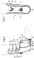
- the ankle orthosis 10 from an articulated cuff 20 with an outer ankle splint 21 and an inner ankle splint 121.
- the two Ankle splints 21, 121 are through one under the heel of the foot extending web 22 connected to each other.
- On the back are the two ankle braces 21, 121 below Cut-out in the heel and the Achilles tendon insertion an elastic, preferably 12 cm wide band 23 connected, that is a defined, limited Has elasticity, so in the applied state of the Ankle orthosis 10, the two ankle splints 21, 121 with a firm fit on both sides of the ankle.
- This band 23 has a transverse elasticity with regard to its length on.
- Both ankle splints 21, 121 have anatomically correct Wells, to adapt to the ankle contours and anatomically correct fit (Fig. 1 and 3).
- the two ankle splints are in the front area 21, 121 of the joint cuff 20 over at least one adjustable webbing 25 or 25 'connected in length, which will be discussed in more detail below.
- a metatarsal 30 On the web 22 of the joint cuff 20 is a metatarsal 30 molded, the medial and lateral tab-shaped is trained. This midfoot part 30 is via a web 35, which is designed as a joint web, connected to the web 22 of the joint sleeve 20.
- tabs 31, 131 of the midfoot part 30 the foot margins laterally and medially (Fig. 1 and 3). Both tabs 31, 131 are also for the connection of two cross straps 40, 140 and for a cross strap 50 trained. The two are over the cross belt 50 Tabs 31, 131 connected to each other.
- the midfoot part 30 is on the sole side of the foot via a highly flexible, as an articulated bridge 35 with the bridge 22 of the joint cuff 20 connected.
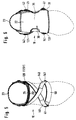
- This joint bridge 35 has increased stiffness on the medial side on (Fig. 6).
- a cross webbing 40, 140 On the medial and lateral tab 31, 131 of the metatarsal 30 is a cross webbing 40, 140 at 41, 141 articulated.
- the cross webbing 140 is of the medial flap 131 over the proximal back of the foot to the Outer ankle splint 21 guided and attached to this, while the other cross webbing 40 from the lateral Tab 31 led to the inner ankle splint 121 and is also attached to this (Fig. 2).
- the cross belt 50 is also convenient with its ends at 41, 141 on the tabs 31, 131 of the metatarsal 30 hinged.
- the highly flexible web 35 of the metatarsal part 30 preferably has a width of about 5 cm. It runs the axis of rotation of this joint formed by the web 35 from dorso-medial to antero-lateral and forms with the longitudinal axis of the foot corresponding to an angle of approximately 10 ° the anatomy of the lower ankle, being other angular positions are also possible.
- the effect of the web 35 of the metatarsal part 30 as a joint to act is based on the fact that the web 35th is made of a thermoplastic material, wherein the articulation through a transverse to the longitudinal direction notch 135 of the foot can still be increased, so that the function of a film hinge is achieved. In this way a high mobility of the foot reached (Fig. 1).
- the joint cuff 20 and the metatarsal part 30 consist of a thermoplastic material. From parts of the thermoplastic material Ankle orthosis 10 are on the skin side with a contact to the skin-holding coating. This Coating is very skin-friendly and can, for example, from a pile fabric or a Fabric with a roughened surface.
- FIGS. 1 to 6 are the two ankle splints 21, 121 of the joint cuff 20 on the front over two on top of each other arranged straps 25, 25 'connected to each other.
- These straps 25, 25 ' which are of the same design, consist of transverse Velcro strips 125, 125 '.
- These Velcro straps 125, 125 ' are on the one side on the Outer ankle splint 21 articulated and from there to the Ankle splint 121 guided, the eyelets 126, 126 ' through which the Velcro strips are pulled.
- Each Velcro strip 125, 125 ' is then with its free End over the Velcro at the end of the band below fixed.
- Cross straps 40, 140 can be changed in their lengths and preferably designed as Velcro strips 40a, 140a (Fig. 2).
- Velcro strips 40a, 140a On the lateral and medial tab 31, 131 of the midfoot part 30 is a Velcro strip 40a and 140a at 41, 141 rotatably articulated.
- the Velcro 140a is from the medial tab 131 to the outer ankle splint 21 performed and on the outside one rotatably attached to the outer ankle splint 21 Passed through eyelet 42. That passed through the eyelet 42 The end of the Velcro tape 140a is then with the Velcro section underneath each Velcro.
- the other Velcro tape 40a is from the lateral tab 31 of the midfoot part 30 to the inner ankle splint 121 guided, on the outside of a rotatable eyelet 142 is attached, through which the Velcro tape 40a is pulled and hooked up according to the Velcro tape 140a is.
Claims (10)
- Support pour la cheville constitué par une manchette d'articulation en forme d'U (20) avec une entretoise (22) en une matière flexible située en dessous du pied, le support (10) étant constitué par une manchette d'articulation (20) avec une attelle de cheville extérieure (21) et une attelle de cheville intérieure (121), les deux attelles de cheville (21, 121) étant reliées l'une a l'autre par une entretoise (22) située sous le talon du pied et sur le côté arrière avec une réservation pour le talon et le début du tendon d'Achille par une large bande (23) ainsi que sur le côté avant dans sa zone supérieure par au moins une sangle (25 ; 25') de longueur réglable et présentant des creux adaptés à l'anatomie et moulés, et par une partie pour le métatarse (30) allant dans le sens transversal sous la plante du pied de manière proximale par rapport aux petites têtes des os du métatarse I-V, partie qui entoure les bords du pied latéralement et médialement et qui forme le raccord pour deux sangles croisées (40, 140) et une sangle transversale (50) et qui est reliée par la sangle transversale (50),
caractérisé en ce quea. la partie pour le métatarse (30) est reliée du côté de la plante du pied par une entretoise (35) extrêmement flexible, qui agit comme une articulation, à l'entretoise (22) de la manchette d'articulation (20) ;b. la partie pour le métatarse (30) est configurée médialement et latéralement en forme de collier, ces colliers formés (31, 131) entourant les bords du pied latéralement et médialement et formant le raccord pour les deux sangles croisées (40, 140) configurées non extensibles et la sangle transversale (50) et étant reliées l'une à l'autre par la sangle transversale,c. l'une des deux sangles croisées (40 ; 140) étant guidée du collier médial (131) par le dos du pied proximal à l'attelle de cheville extérieure (21) et étant fixée à celle-ci et l'autre sangle croisée (40) étant guidée du collier latéral (31) à l'attelle de cheville intérieure (121) et étant fixée à celle-ci,d. le support de cheville étant approprié en particulier pour le traitement fonctionnel précoce des ruptures de ligaments fibulaires récentes et de graves distorsions du tarse. - Support de cheville selon la revendication 1, caractérisé en ce que l'entretoise extrêmement flexible (35) présente une largeur d'environ 5 cm.
- Support de cheville selon l'une des revendications 1 et 2, caractérisé en ce que l'axe de rotation de l'articulation formée par l'entretoise extrêmement flexible (35) va de dorso-médial à antéro-latéral et forme, avec l'axe longitudinal du pied, un angle d'environ 10° correspondant à l'anatomie de l'articulation tibiotarsienne inférieure du pied.
- Support de cheville selon l'une des revendications 1 à 3, caractérisé en ce que la manchette d'articulation (20) et la partie pour le métatarse (30) est en matière thermoplastique.
- Support de cheville selon l'une des revendications 1 à 4, caractérisé en ce que les parties constituées par une matière thermoplastique sont pourvues, côté peau, d'un revêtement qui maintient le contact avec la peau.
- Support de cheville selon l'une des revendications 1 à 5, caractérisé en ce que la bande (23) qui relie les deux attelles de cheville (21, 121) dans la zone arrière présente une élasticité transversale.
- Support de cheville selon l'une des revendications 1 à 6, caractérisé en ce que la bande (23) présente une largeur d'environ 12 cm.
- Support de cheville selon l'une des revendications 1 à 7, caractérisé en ce que les deux attelles de cheville (21, 121) sont reliées l'une à l'autre sur leur côté avant par deux sangles (25, 25') qui sont configurées comme des bandes auto-agrippantes (125, 125') allant dans le sens transversal, qui sont articulées du côté d'une extrémité à l'attelle de cheville extérieure (21) et qui sont guidées en partant de là vers l'attelle de cheville intérieure (121), qui, ici, passent par des oeillets (126, 126') fixés sur l'attelle de cheville intérieure (121), qui sont tendues vers le côté latéral et qui sont ensuite fermées de manière auto-agrippante.
- Support de cheville selon l'une des revendications 1 à 8, caractérisé en ce que les sangles croisées (40, 140), fixées aux colliers (31, 131) de la partie pour le métatarse (30), sont configurées comme des bandes auto-agrippantes (40a, 140a), une bande auto-agrippante (40a ; 140a) étant respectivement articulée de manière rotative sur le collier médial et sur le collier latéral (131, 31) de la partie pour le métatarse (30), une bande auto-agrippante (140a) allant du collier médial (131) à l'attelle de cheville extérieure (21), sur le côté extérieur de laquelle un oeillet rotatif (42) est fixé, par lequel la bande auto-agrippante (140a) est tendue et fermée de manière auto-agrippante, l'autre bande auto-agrippante (40a) étant guidée du collier latéral (31) à l'attelle de cheville intérieure (121), sur le côté extérieur de laquelle un oeillet rotatif (142) est fixé par lequel la bande auto-agrippante (40a) est tendue et fermée de manière auto-agrippante.
- Support de cheville selon l'une des revendications 1 à 9, caractérisé en ce que l'entretoise (35) de la partie pour lee métatarse (30) qui forme l'articulation présente, sur le côté médial, une rigidité accrue.
Applications Claiming Priority (2)
| Application Number | Priority Date | Filing Date | Title |
|---|---|---|---|
| DE4318588 | 1993-06-04 | ||
| DE4318588A DE4318588C1 (de) | 1993-06-04 | 1993-06-04 | Sprunggelenkorthese mit U-förmiger Gelenkmanschette und biegsamen Steg |
Publications (2)
| Publication Number | Publication Date |
|---|---|
| EP0627205A1 EP0627205A1 (fr) | 1994-12-07 |
| EP0627205B1 true EP0627205B1 (fr) | 1998-08-12 |
Family
ID=6489639
Family Applications (1)
| Application Number | Title | Priority Date | Filing Date |
|---|---|---|---|
| EP94107110A Expired - Lifetime EP0627205B1 (fr) | 1993-06-04 | 1994-05-06 | Support pour la cheville |
Country Status (4)
| Country | Link |
|---|---|
| US (1) | US5472411A (fr) |
| EP (1) | EP0627205B1 (fr) |
| AT (1) | ATE169487T1 (fr) |
| DE (2) | DE4318588C1 (fr) |
Families Citing this family (41)
| Publication number | Priority date | Publication date | Assignee | Title |
|---|---|---|---|---|
| US5716335A (en) * | 1993-07-29 | 1998-02-10 | Royce Medical Company | Ankle brace with adjustable heel strap |
| US5951504A (en) * | 1993-07-29 | 1999-09-14 | Royce Medical Products | Ankle brace with adjustable heel strap |
| US5741222A (en) * | 1994-06-10 | 1998-04-21 | Fiore; Russell D. | Ankle joint support |
| US5579552A (en) * | 1995-02-10 | 1996-12-03 | Henry; Jesse E. | Toddler restraint apparatus |
| NZ286052A (en) * | 1996-02-22 | 1998-09-24 | Bodyworks Healthcare Ltd | Support including two straps fastened to a boot element in front of, and in the location of, the ankle |
| US5718673A (en) * | 1996-08-06 | 1998-02-17 | Shipstead; Clare | Foot support devices and methods |
| US5860423A (en) * | 1996-12-06 | 1999-01-19 | Thompson; Terry | Ankle-foot orthosis |
| US6022332A (en) * | 1997-06-12 | 2000-02-08 | Private Label Creations, Inc. | Ankle brace allowing flexion and extension |
| US5954717A (en) * | 1997-09-25 | 1999-09-21 | Radiotherapeutics Corporation | Method and system for heating solid tissue |
| US6358246B1 (en) | 1999-06-25 | 2002-03-19 | Radiotherapeutics Corporation | Method and system for heating solid tissue |
| DE19802511C2 (de) | 1998-01-23 | 2000-11-30 | Beiersdorf Ag | Bandage für das Sprunggelenk |
| US6602216B1 (en) | 1998-05-18 | 2003-08-05 | William E. Nordt, III | Plantar fascia tension device |
| US6267742B1 (en) * | 1998-09-29 | 2001-07-31 | Brown Medical Industries | Biplanar foot dorsiflexion collapsible posterior splint |
| DE19917822B4 (de) * | 1999-04-20 | 2006-02-09 | Bauerfeind Orthopädie GmbH & Co. KG | Sprunggelenkorthese |
| DE19941368B4 (de) * | 1999-08-31 | 2005-08-11 | Helmut Röck GmbH | Orthese zur Versorgung bei allgemeinen Fußhebeschwächen |
| CA2388376A1 (fr) | 1999-09-08 | 2001-03-15 | Curon Medical, Inc. | Systemes et techniques de surveillance et de gestion de dispositifs medicaux |
| DE10022524A1 (de) * | 2000-05-09 | 2001-11-15 | Beiersdorf Ag | Bandage für das Sprunggelenk |
| DE10037342A1 (de) * | 2000-07-29 | 2002-02-07 | Beiersdorf Ag | Bandage für das Sprunggelenk |
| DE10055932A1 (de) * | 2000-11-10 | 2002-05-23 | Beiersdorf Ag | Bandage für das Sprunggelenk |
| US6641550B1 (en) * | 2002-05-31 | 2003-11-04 | Kerry Johnson | Orthopedic support for the treatment of heel pain |
| US6929617B2 (en) * | 2002-06-18 | 2005-08-16 | Beiersdorf Inc. | Nonbulky ankle brace for use with footwear |
| US6602215B1 (en) * | 2002-07-03 | 2003-08-05 | Douglas H. Richie, Jr. | Ankle brace with arch sling support |
| US20040260226A1 (en) * | 2002-11-20 | 2004-12-23 | Gilmour Robert Farrer | Ankle strap |
| US7014621B2 (en) * | 2002-12-06 | 2006-03-21 | Mueller Sports Medicine, Inc. | Ankle brace |
| US7094213B1 (en) | 2003-04-10 | 2006-08-22 | Gerry Cook | Adjustable foot and ankle device for gait control |
| US7128725B2 (en) * | 2003-10-16 | 2006-10-31 | David Rabe | Ankle brace |
| US20060229542A1 (en) * | 2005-04-06 | 2006-10-12 | Sinreich Norman D | Orthosis |
| US20070032359A1 (en) * | 2005-08-02 | 2007-02-08 | Brian Toronto | Proprioception enhancement bands |
| DE102006041195A1 (de) * | 2006-09-05 | 2008-03-06 | Bauerfeind Ag | Sprunggelenkorthese |
| US20080294083A1 (en) | 2007-05-21 | 2008-11-27 | Julia Chang | Orthopedic device |
| US20090192427A1 (en) * | 2008-01-29 | 2009-07-30 | Brown Medical Industries | Walking splint with anti-skid bottom |
| US20090192428A1 (en) * | 2008-01-30 | 2009-07-30 | Brown Medical Industries | Soft wrap for treating plantar fasciitis |
| PL2612631T3 (pl) * | 2009-06-16 | 2015-03-31 | Bock Healthcare Gmbh | Opatrunek podtrzymujący |
| US9707119B2 (en) * | 2010-06-21 | 2017-07-18 | Under Armour, Inc. | Foot support article |
| US11026473B2 (en) * | 2011-05-19 | 2021-06-08 | Under Armour, Inc. | Foot support article |
| AU2015292252B2 (en) * | 2014-07-25 | 2020-03-19 | Pod Global Ip Pty Ltd | Functional ankle supports with improved movement and comfort |
| DE102014113363A1 (de) * | 2014-09-17 | 2016-03-17 | Petra Meyer-Clasen | Orthese, insbesondere Fußhebeorthese |
| DE102015000783A1 (de) * | 2015-01-26 | 2016-07-28 | Otto Bock Healthcare Gmbh | Knöchelorthese |
| DE102018124932A1 (de) * | 2018-10-09 | 2020-04-09 | Betterguards Technology Gmbh | Fußbewegungsdämpfungsvorrichtung und Schuh |
| WO2020077431A1 (fr) * | 2018-10-16 | 2020-04-23 | Lester Ponce | Ensemble de bandage permettant d'imiter une action musculaire |
| US20210121312A1 (en) * | 2019-10-29 | 2021-04-29 | Bryan E. Kilbey | Ankle Brace with Anti-Rotation Feature |
Family Cites Families (16)
| Publication number | Priority date | Publication date | Assignee | Title |
|---|---|---|---|---|
| US2994322A (en) * | 1959-01-12 | 1961-08-01 | Charles C Cullen | Protective supporter |
| US4313433A (en) * | 1979-10-09 | 1982-02-02 | Cramer Products, Inc. | Ankle stabilizer |
| US4323058A (en) * | 1980-10-14 | 1982-04-06 | Detty Garnett E | Ankle brace |
| US4345590A (en) * | 1980-10-26 | 1982-08-24 | Kuniaki Yamazaki | Support bandage |
| US4597395A (en) * | 1985-08-23 | 1986-07-01 | Barlow, Inc. | Ankle support including a heel lock and a crossover strap |
| US4630600A (en) * | 1986-02-18 | 1986-12-23 | Pro-Tec Sports, Inc. | Ankle brace and protector |
| US4869267A (en) * | 1988-05-10 | 1989-09-26 | Royce Medical Company | Adjustable tension ankle support |
| US5000195A (en) * | 1988-06-21 | 1991-03-19 | Deroyal Industries, Inc. | Ankle splint |
| DE3909922A1 (de) * | 1988-08-01 | 1990-02-08 | Ott Gerhard | Flussfixierungsschiene |
| US4962768A (en) * | 1988-09-12 | 1990-10-16 | Lawrence Thompson Stromgren | Stirrup-lock ankle support |
| DE3840714A1 (de) * | 1988-12-02 | 1990-06-07 | Bauerfeind Gmbh | Sprunggelenkorthese |
| US4938222A (en) * | 1989-03-20 | 1990-07-03 | Bier Jr John D | Therapeutic bandage |
| CH678808A5 (fr) * | 1989-08-03 | 1991-11-15 | Max Amrein | |
| US5016623A (en) * | 1990-03-14 | 1991-05-21 | Krahenbuhl Doug W | Ankle support |
| DE4112069A1 (de) * | 1991-04-12 | 1992-10-15 | Bauerfeind Gmbh | Sprunggelenkorthese |
| US5139479A (en) * | 1991-04-26 | 1992-08-18 | Camp International, Inc. | Ankle sleeve |
-
1993
- 1993-06-04 DE DE4318588A patent/DE4318588C1/de not_active Expired - Fee Related
-
1994
- 1994-05-06 DE DE59406640T patent/DE59406640D1/de not_active Expired - Fee Related
- 1994-05-06 EP EP94107110A patent/EP0627205B1/fr not_active Expired - Lifetime
- 1994-05-06 AT AT94107110T patent/ATE169487T1/de not_active IP Right Cessation
- 1994-05-31 US US08/251,323 patent/US5472411A/en not_active Expired - Fee Related
Also Published As
| Publication number | Publication date |
|---|---|
| ATE169487T1 (de) | 1998-08-15 |
| EP0627205A1 (fr) | 1994-12-07 |
| US5472411A (en) | 1995-12-05 |
| DE59406640D1 (de) | 1998-09-17 |
| DE4318588C1 (de) | 1994-08-25 |
Similar Documents
| Publication | Publication Date | Title |
|---|---|---|
| EP0627205B1 (fr) | Support pour la cheville | |
| EP2612631B1 (fr) | Bande de contention | |
| EP1179325B1 (fr) | Bandage pour la cheville | |
| EP2219568B1 (fr) | Système orthopédique pour l'articulation du tarse | |
| DE3525753A1 (de) | Fuss-stuetzbandage | |
| EP1093779B1 (fr) | Bandage pour décharger un muscle déchiré | |
| EP0931528B1 (fr) | Bandage pour la cheville | |
| EP1280487B1 (fr) | Bandage pour l'articulation du pied | |
| DE2913606C2 (fr) | ||
| DE4291109C2 (de) | Stützverband für ein Fußgelenk mit Hauptstützteil, Unterschenkel- und Fußteil sowie beidseitigen Stützteilen | |
| EP3068351B1 (fr) | Orthèse | |
| DE102019119079A1 (de) | Sprunggelenkorthese | |
| EP3854357B1 (fr) | Bandage pour articulation de genou | |
| EP3854358A1 (fr) | Bandage d'articulation de genou | |
| DE202020100382U1 (de) | Kniegelenkbandage | |
| DE10055932A1 (de) | Bandage für das Sprunggelenk | |
| DE202020100383U1 (de) | Kniegelenkbandage | |
| DE2733357A1 (de) | Orthese zur nachbehandlung von vorfussoperationen | |
| EP0824014A1 (fr) | Chevillière | |
| DE19733423B4 (de) | Fußstützeinrichtung mit einer Manschette | |
| DE102009050383B3 (de) | Stützbandage | |
| DE3433843A1 (de) | Kniestuetze zur verhinderung von rotationen | |
| DE2259945A1 (de) | Orthopaedische schiene zum stillegen von gliedern und dergleichen |
Legal Events
| Date | Code | Title | Description |
|---|---|---|---|
| PUAI | Public reference made under article 153(3) epc to a published international application that has entered the european phase |
Free format text: ORIGINAL CODE: 0009012 |
|
| AK | Designated contracting states |
Kind code of ref document: A1 Designated state(s): AT BE DE ES IT NL SE |
|
| 17P | Request for examination filed |
Effective date: 19941021 |
|
| 17Q | First examination report despatched |
Effective date: 19961220 |
|
| GRAG | Despatch of communication of intention to grant |
Free format text: ORIGINAL CODE: EPIDOS AGRA |
|
| GRAG | Despatch of communication of intention to grant |
Free format text: ORIGINAL CODE: EPIDOS AGRA |
|
| GRAH | Despatch of communication of intention to grant a patent |
Free format text: ORIGINAL CODE: EPIDOS IGRA |
|
| GRAH | Despatch of communication of intention to grant a patent |
Free format text: ORIGINAL CODE: EPIDOS IGRA |
|
| GRAA | (expected) grant |
Free format text: ORIGINAL CODE: 0009210 |
|
| STAA | Information on the status of an ep patent application or granted ep patent |
Free format text: STATUS: THE PATENT HAS BEEN GRANTED |
|
| AK | Designated contracting states |
Kind code of ref document: B1 Designated state(s): AT BE DE ES IT NL SE |
|
| PG25 | Lapsed in a contracting state [announced via postgrant information from national office to epo] |
Ref country code: IT Free format text: LAPSE BECAUSE OF FAILURE TO SUBMIT A TRANSLATION OF THE DESCRIPTION OR TO PAY THE FEE WITHIN THE PRE;WARNING: LAPSES OF ITALIAN PATENTS WITH EFFECTIVE DATE BEFORE 2007 MAY HAVE OCCURRED AT ANY TIME BEFORE 2007. THE CORRECT EFFECTIVE DATE MAY BE DIFFERENT FROM THE ONE RECORDED.SCRIBED TIME-LIMIT Effective date: 19980812 Ref country code: ES Free format text: THE PATENT HAS BEEN ANNULLED BY A DECISION OF A NATIONAL AUTHORITY Effective date: 19980812 |
|
| REF | Corresponds to: |
Ref document number: 169487 Country of ref document: AT Date of ref document: 19980815 Kind code of ref document: T |
|
| REF | Corresponds to: |
Ref document number: 59406640 Country of ref document: DE Date of ref document: 19980917 |
|
| PG25 | Lapsed in a contracting state [announced via postgrant information from national office to epo] |
Ref country code: SE Free format text: LAPSE BECAUSE OF FAILURE TO SUBMIT A TRANSLATION OF THE DESCRIPTION OR TO PAY THE FEE WITHIN THE PRESCRIBED TIME-LIMIT Effective date: 19981112 |
|
| PLBE | No opposition filed within time limit |
Free format text: ORIGINAL CODE: 0009261 |
|
| 26N | No opposition filed | ||
| PGFP | Annual fee paid to national office [announced via postgrant information from national office to epo] |
Ref country code: DE Payment date: 20040531 Year of fee payment: 11 |
|
| PG25 | Lapsed in a contracting state [announced via postgrant information from national office to epo] |
Ref country code: DE Free format text: LAPSE BECAUSE OF NON-PAYMENT OF DUE FEES Effective date: 20061201 |
|
| PGFP | Annual fee paid to national office [announced via postgrant information from national office to epo] |
Ref country code: NL Payment date: 20070514 Year of fee payment: 14 |
|
| PGFP | Annual fee paid to national office [announced via postgrant information from national office to epo] |
Ref country code: AT Payment date: 20070515 Year of fee payment: 14 |
|
| PGFP | Annual fee paid to national office [announced via postgrant information from national office to epo] |
Ref country code: BE Payment date: 20070531 Year of fee payment: 14 |
|
| BERE | Be: lapsed |
Owner name: *BEIERSDORF A.G. Effective date: 20080531 |
|
| PG25 | Lapsed in a contracting state [announced via postgrant information from national office to epo] |
Ref country code: NL Free format text: LAPSE BECAUSE OF NON-PAYMENT OF DUE FEES Effective date: 20081201 Ref country code: DE Free format text: LAPSE BECAUSE OF NON-PAYMENT OF DUE FEES Effective date: 20050531 |
|
| PG25 | Lapsed in a contracting state [announced via postgrant information from national office to epo] |
Ref country code: AT Free format text: LAPSE BECAUSE OF NON-PAYMENT OF DUE FEES Effective date: 20080506 |
|
| PG25 | Lapsed in a contracting state [announced via postgrant information from national office to epo] |
Ref country code: BE Free format text: LAPSE BECAUSE OF NON-PAYMENT OF DUE FEES Effective date: 20080531 |