EP0622191A1 - Wischvorrichtung einer Stichtiefdruckmaschine - Google Patents
Wischvorrichtung einer Stichtiefdruckmaschine Download PDFInfo
- Publication number
- EP0622191A1 EP0622191A1 EP94810162A EP94810162A EP0622191A1 EP 0622191 A1 EP0622191 A1 EP 0622191A1 EP 94810162 A EP94810162 A EP 94810162A EP 94810162 A EP94810162 A EP 94810162A EP 0622191 A1 EP0622191 A1 EP 0622191A1
- Authority
- EP
- European Patent Office
- Prior art keywords
- cylinder
- cleaning
- wiping
- wiping cylinder
- nozzles
- Prior art date
- Legal status (The legal status is an assumption and is not a legal conclusion. Google has not performed a legal analysis and makes no representation as to the accuracy of the status listed.)
- Granted
Links
- 238000004140 cleaning Methods 0.000 claims abstract description 39
- 239000007788 liquid Substances 0.000 claims abstract description 12
- 239000000463 material Substances 0.000 claims abstract description 12
- 239000004753 textile Substances 0.000 claims abstract description 12
- 229920002994 synthetic fiber Polymers 0.000 claims abstract description 6
- 238000009434 installation Methods 0.000 claims description 9
- 239000012209 synthetic fiber Substances 0.000 claims description 3
- 229910000831 Steel Inorganic materials 0.000 description 8
- 239000010959 steel Substances 0.000 description 8
- 230000001154 acute effect Effects 0.000 description 3
- 238000011109 contamination Methods 0.000 description 1
- 238000001035 drying Methods 0.000 description 1
- 230000000694 effects Effects 0.000 description 1
- 238000012423 maintenance Methods 0.000 description 1
- 230000002093 peripheral effect Effects 0.000 description 1
- 238000007790 scraping Methods 0.000 description 1
- 238000000926 separation method Methods 0.000 description 1
- 239000007787 solid Substances 0.000 description 1
- 239000007921 spray Substances 0.000 description 1
- 238000005507 spraying Methods 0.000 description 1
Images
Classifications
-
- B—PERFORMING OPERATIONS; TRANSPORTING
- B41—PRINTING; LINING MACHINES; TYPEWRITERS; STAMPS
- B41F—PRINTING MACHINES OR PRESSES
- B41F9/00—Rotary intaglio printing presses
- B41F9/06—Details
- B41F9/08—Wiping mechanisms
- B41F9/16—Removing or recovering ink from wiping mechanisms
-
- B—PERFORMING OPERATIONS; TRANSPORTING
- B41—PRINTING; LINING MACHINES; TYPEWRITERS; STAMPS
- B41F—PRINTING MACHINES OR PRESSES
- B41F9/00—Rotary intaglio printing presses
- B41F9/06—Details
- B41F9/08—Wiping mechanisms
- B41F9/10—Doctors, scrapers, or like devices
- B41F9/1018—Doctors, scrapers, or like devices using a wiping cylinder
Definitions
- the present invention relates to a device for wiping a machine for intaglio printing comprising a wiping cylinder and an installation for the continuous cleaning of said cylinder, this installation comprising a container for receiving the cleaning liquid.
- a device for wiping a machine for intaglio printing comprising a wiping cylinder and an installation for the continuous cleaning of said cylinder, this installation comprising a container for receiving the cleaning liquid.
- which acts permanently on the wiping cylinder and cleaning elements in contact with the periphery of the wiping cylinder comprising, in the direction of rotation of this cylinder, a first cleaning element, which removes most of the ink from the wiping cylinder, followed, at defined distances, by several other elements constituted by brushes and / or scrapers, at least one row of nozzles parallel to the axis of the wiping cylinder, the nozzles being arranged for ejecting the cleaning liquid in the region of the region of contact of said first cleaning element with the wiping cylinder.
- doctor blade is quite effective, since it alone removes practically 90% of the ink from the surface of the wiping cylinder, it has been found in use that, due to friction important between the doctor blade and the cylinder, friction which is reinforced by the angle inclination acute scraping with respect to the periphery of the wiping cylinder, the surface of the cylinder undergoes very great wear forces which risk damaging it, all the more so since this surface is made of synthetic material, in particular PVC. In addition, it was found that said doctor blade very quickly becomes sharp, which increases the wear of the wiping cylinder and forces the user to replace this doctor blade about every 24 hours.
- the present invention proposes to overcome the drawbacks inherent in a steel doctor blade by sparing the surface of the wiping cylinder while reducing the cost of maintenance.
- the installation according to the invention is characterized in that the first cleaning element is made of textile material in the form of a strip which is mounted folded back on itself on and along a rigid support, so to overflow from it.
- This textile material is preferably made of porous synthetic fibers.
- a first cleaning element is thus obtained which is as effective as a rigid scraper but which, thanks to its flexibility, does not risk damaging the surface of the wiping cylinder, which therefore increases the life of the latter. Another advantage is that the wear being less than with a steel scraper, the life of the cleaning element itself is longer, of the order of eight days, which is clearly more economical for the user.
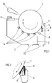
- FIG. 1 represents a schematic view of the device for cleaning the wiping cylinder.
- Figure 2 is an enlarged partial view of the contact area of the first cleaning element with the wiping cylinder.
- the wiping device comprises a wiping cylinder 1, rotating in the direction of arrow F, intended to be in permanent contact with the plate cylinder not shown, the peripheral direction of rotation of this wiping cylinder 1 being opposite to that of the plate cylinder.
- This wiping cylinder 1 is partially arranged inside a container 2 in which the cleaning installation is mounted.
- the surface of the wiping cylinder 1 is made of synthetic material, in particular PVC, which ensures good wiping of the plate cylinder.
- the cleaning installation comprises, in a manner known per se, several cleaning elements constituted, in the example considered, by a doctor blade 3 forming an obtuse angle with the periphery of the cylinder 1 located following this doctor blade direction of rotation of said cylinder, and by brushes 4 arranged at a distance from one another around the periphery of cylinder 1.
- a first cleaning element 5 consisting of a textile material of porous synthetic fibers, with a thickness of between 5 and 20 mm, preferably 10 mm, sold for example by the company 3M under the name "Scotch-Brite" or "hand pad".
- This textile material is in the form of a strip whose dimension in the axial direction of the cylinder corresponds to the length of the latter so that the entire surface is covered, and which is mounted, folded back on itself (FIG. 2), on and along a support 6 so as to protrude therefrom.
- the inclination of the support 6 is adjustable to adjust the contact pressure between the strip of textile material and the surface of the cylinder 1, this support 6 having the same configuration as the doctor blade which, in the previous installations, was intended to carry the steel scraper.
- This element 5 which is fixed in any known manner to the support 6, is intended to apply tangentially over the entire length of the wiping cylinder 1 during the rotation thereof, forming an acute angle with the periphery of the cylinder located after this element in the direction of rotation of the cylinder, and to rub its surface so as to remove approximately 90% of the quantity of ink present on the surface of the wiping cylinder.
- Above the first cleaning element 5 is provided a row of spray nozzles 7 directed just before the contact zone of said element 5 with the cylinder 1.
- nozzles 8 In the support 6 is provided a second row of nozzles 8 whose mouths are directed towards inside the fold formed by the first cleaning element 5. These nozzles 7 and 8 are intended to send under pressure a cleaning liquid which, on the one hand, deterges the ink and, on the other hand, wets and rinses permanently cleaning element 5, which prevents fouling thereof during friction.
- the cleaning liquid from the nozzles 7, 8 and the nozzles associated with the brushes 4 is collected in the container 2 and flows through outlet orifices 11 so that the wiping cylinder 1 is not immersed in the soiled liquid.
- a separation wall 2 ′ in the container 2 makes it possible to separate the cleaning liquid coming from the nozzles 7, 8, which is soiled by the greatest amount of ink from the less dirty liquid coming from the nozzles associated with the brushes 4.
Landscapes
- Engineering & Computer Science (AREA)
- Mechanical Engineering (AREA)
- Inking, Control Or Cleaning Of Printing Machines (AREA)
- Rotary Presses (AREA)
- Screen Printers (AREA)
- Treatment Of Fiber Materials (AREA)
Applications Claiming Priority (2)
| Application Number | Priority Date | Filing Date | Title |
|---|---|---|---|
| CH1318/93 | 1993-04-30 | ||
| CH131893 | 1993-04-30 |
Publications (2)
| Publication Number | Publication Date |
|---|---|
| EP0622191A1 true EP0622191A1 (de) | 1994-11-02 |
| EP0622191B1 EP0622191B1 (de) | 1997-01-22 |
Family
ID=4207639
Family Applications (1)
| Application Number | Title | Priority Date | Filing Date |
|---|---|---|---|
| EP94810162A Expired - Lifetime EP0622191B1 (de) | 1993-04-30 | 1994-03-16 | Wischvorrichtung einer Stichtiefdruckmaschine |
Country Status (10)
| Country | Link |
|---|---|
| US (1) | US5390598A (de) |
| EP (1) | EP0622191B1 (de) |
| JP (1) | JP3469303B2 (de) |
| KR (1) | KR100330114B1 (de) |
| CN (1) | CN1036641C (de) |
| AT (1) | ATE148032T1 (de) |
| AU (1) | AU664965B2 (de) |
| CA (1) | CA2119628A1 (de) |
| DE (1) | DE69401525T2 (de) |
| RU (1) | RU2119432C1 (de) |
Cited By (4)
| Publication number | Priority date | Publication date | Assignee | Title |
|---|---|---|---|---|
| EP1055516A1 (de) * | 1999-05-25 | 2000-11-29 | Komori Corporation | Wischvorrichtung in einer Tiefdruckmaschine |
| EP1790473A1 (de) | 2005-11-25 | 2007-05-30 | Kba-Giori S.A. | Verfahren zur Erfassung vom Eintreten von Druckfehlern auf Druckbogen während deren Bearbeitung in einer Druckmaschine |
| WO2007085862A1 (en) * | 2006-01-30 | 2007-08-02 | De La Rue International Limited | Intaglio plate wiping system |
| US8613254B2 (en) | 2005-11-25 | 2013-12-24 | Kba-Notasys Sa | Method for detection of occurrence of printing errors on printed substrates during processing thereof on a printing press |
Families Citing this family (20)
| Publication number | Priority date | Publication date | Assignee | Title |
|---|---|---|---|---|
| JP3234101B2 (ja) * | 1994-05-09 | 2001-12-04 | 株式会社リコー | 被記録材の皮膜状画像形成物質除去装置 |
| US5575211A (en) * | 1994-10-28 | 1996-11-19 | Hycorr Machine Corporation | Washing Arrangement for rotary printer |
| UA28061C2 (uk) * | 1996-09-02 | 2000-10-16 | Де Ля Рю Жіорі С.А. | Спосіб приготування свіжого мийного розчину та обробки використаного мийного розчину і пристрій для його здійснення |
| IT1297042B1 (it) * | 1997-12-31 | 1999-08-03 | De La Rue Giori Sa | Procedimento di produzione di soluzione di asciugatura fresca e di trattamento della soluzione di asciugatura usata e dispositivo di |
| US6196126B1 (en) | 1999-01-12 | 2001-03-06 | Intex Corporation | Method and apparatus for preventing pigment buildup during a rotary screen printing process |
| EP1361046A1 (de) * | 2002-05-06 | 2003-11-12 | Kba-Giori S.A. | Sprühdüse für eine Reinigungsvorrichtung in einer Druckmaschine |
| JP4706059B2 (ja) * | 2005-07-20 | 2011-06-22 | 独立行政法人 国立印刷局 | ワイピング自動洗浄装置 |
| EP1764216A1 (de) * | 2005-09-16 | 2007-03-21 | Kba-Giori S.A. | Vorrichtung zur Beschichtung eines Zylinders, insbesondere eines Wischzylinders einer Tiefdruckmaschine |
| KR100667882B1 (ko) * | 2005-10-04 | 2007-01-11 | 주식회사 디엠에스 | 롤프린트 장치 |
| EP1844930A1 (de) * | 2006-04-11 | 2007-10-17 | Kba-Giori S.A. | Wischvorrichtung einer Druckmaschine |
| US8281717B2 (en) * | 2007-07-25 | 2012-10-09 | Air Motion Systems, Inc. | Printing cylinder cleaning system |
| KR100887387B1 (ko) * | 2007-08-24 | 2009-03-06 | 삼성전기주식회사 | 인쇄회로기판 제조장치 및 제조방법 |
| JP2013056541A (ja) * | 2011-08-15 | 2013-03-28 | Komori Corp | ワイピング装置 |
| CN103302968B (zh) * | 2013-06-25 | 2016-02-24 | 北京印钞有限公司 | 凹印机擦墨辊清洗方法及装置 |
| CN103738054B (zh) * | 2013-12-20 | 2016-08-17 | 深圳劲嘉集团股份有限公司 | 一种凹版印刷机自动洗版装置及实现方法 |
| CN106379052B (zh) * | 2016-11-17 | 2018-01-19 | 重庆强大巴郡知识产权服务有限公司 | 瓷砖印花装置 |
| JP2018106063A (ja) * | 2016-12-27 | 2018-07-05 | エスプリンティンソリューション株式会社 | 画像形成装置 |
| CN108248208A (zh) * | 2018-01-30 | 2018-07-06 | 海宁美力针织有限公司 | 一种沙发套生产用印染装置 |
| CN113524903A (zh) * | 2021-07-14 | 2021-10-22 | 山东锦龙包装有限公司 | 一种食品包装袋彩印颜料刮除装置 |
| CN113771489B (zh) * | 2021-07-29 | 2023-04-28 | 阜阳市新世纪包装彩印有限公司 | 一种酒盒印刷用具有干墨刮除机构的印刷头 |
Citations (3)
| Publication number | Priority date | Publication date | Assignee | Title |
|---|---|---|---|---|
| FR1517914A (fr) * | 1967-02-06 | 1968-03-22 | Procédé de nettoyage du cylindre essuyeur dans les machines à cylindres pour impression en taille douce et dispositif de mise en oeuvre dudit procédé | |
| CH596988A5 (de) * | 1976-09-17 | 1978-03-31 | De La Rue Giori Sa | |
| EP0514756A1 (de) * | 1991-05-22 | 1992-11-25 | Komori Corporation | Rakelvorrichtung für Tiefdruckmaschine |
Family Cites Families (5)
| Publication number | Priority date | Publication date | Assignee | Title |
|---|---|---|---|---|
| US4135448A (en) * | 1974-09-11 | 1979-01-23 | Moestue Hans J | Mechanism for cleaning a cylinder of an offset lithographic printing press |
| JPS58101060A (ja) * | 1981-12-12 | 1983-06-16 | Komori Printing Mach Co Ltd | 凹版印刷機のワイピング装置 |
| JPH02215533A (ja) * | 1989-02-17 | 1990-08-28 | B J Trading Kk | 印刷機のインキ供給ローラ洗浄装置 |
| CH681875A5 (de) * | 1990-08-17 | 1993-06-15 | De La Rue Giori Sa | |
| CA2079994C (en) * | 1991-10-17 | 2004-03-30 | Johannes Georg Schaede | Wiping device of an intaglio printing machine |
-
1994
- 1994-03-16 DE DE69401525T patent/DE69401525T2/de not_active Expired - Fee Related
- 1994-03-16 AT AT94810162T patent/ATE148032T1/de not_active IP Right Cessation
- 1994-03-16 EP EP94810162A patent/EP0622191B1/de not_active Expired - Lifetime
- 1994-03-22 AU AU57929/94A patent/AU664965B2/en not_active Ceased
- 1994-03-22 CA CA002119628A patent/CA2119628A1/en not_active Abandoned
- 1994-03-25 US US08/217,976 patent/US5390598A/en not_active Expired - Fee Related
- 1994-04-01 JP JP06490294A patent/JP3469303B2/ja not_active Expired - Fee Related
- 1994-04-19 CN CN94104035A patent/CN1036641C/zh not_active Expired - Fee Related
- 1994-04-29 RU RU94015234A patent/RU2119432C1/ru active
- 1994-04-30 KR KR1019940009406A patent/KR100330114B1/ko not_active IP Right Cessation
Patent Citations (3)
| Publication number | Priority date | Publication date | Assignee | Title |
|---|---|---|---|---|
| FR1517914A (fr) * | 1967-02-06 | 1968-03-22 | Procédé de nettoyage du cylindre essuyeur dans les machines à cylindres pour impression en taille douce et dispositif de mise en oeuvre dudit procédé | |
| CH596988A5 (de) * | 1976-09-17 | 1978-03-31 | De La Rue Giori Sa | |
| EP0514756A1 (de) * | 1991-05-22 | 1992-11-25 | Komori Corporation | Rakelvorrichtung für Tiefdruckmaschine |
Cited By (6)
| Publication number | Priority date | Publication date | Assignee | Title |
|---|---|---|---|---|
| EP1055516A1 (de) * | 1999-05-25 | 2000-11-29 | Komori Corporation | Wischvorrichtung in einer Tiefdruckmaschine |
| US6341556B1 (en) | 1999-05-25 | 2002-01-29 | Komori Corporation | Wiping device of intaglio printing press |
| EP1790473A1 (de) | 2005-11-25 | 2007-05-30 | Kba-Giori S.A. | Verfahren zur Erfassung vom Eintreten von Druckfehlern auf Druckbogen während deren Bearbeitung in einer Druckmaschine |
| US8613254B2 (en) | 2005-11-25 | 2013-12-24 | Kba-Notasys Sa | Method for detection of occurrence of printing errors on printed substrates during processing thereof on a printing press |
| WO2007085862A1 (en) * | 2006-01-30 | 2007-08-02 | De La Rue International Limited | Intaglio plate wiping system |
| EA013550B1 (ru) * | 2006-01-30 | 2010-06-30 | Де Ля Рю Интернэшнл Лимитед | Система удаления краски с формы глубокой печати |
Also Published As
| Publication number | Publication date |
|---|---|
| KR100330114B1 (ko) | 2002-07-27 |
| JP3469303B2 (ja) | 2003-11-25 |
| ATE148032T1 (de) | 1997-02-15 |
| RU2119432C1 (ru) | 1998-09-27 |
| CN1116162A (zh) | 1996-02-07 |
| CN1036641C (zh) | 1997-12-10 |
| CA2119628A1 (en) | 1994-10-31 |
| DE69401525T2 (de) | 1997-07-31 |
| EP0622191B1 (de) | 1997-01-22 |
| US5390598A (en) | 1995-02-21 |
| AU664965B2 (en) | 1995-12-07 |
| JPH06312501A (ja) | 1994-11-08 |
| AU5792994A (en) | 1994-11-03 |
| DE69401525D1 (de) | 1997-03-06 |
Similar Documents
| Publication | Publication Date | Title |
|---|---|---|
| EP0622191B1 (de) | Wischvorrichtung einer Stichtiefdruckmaschine | |
| EP0511883B1 (de) | Siebdruckverfahren und Vorrichtung zum Drucken einer Dekorschicht an Glasscheiben | |
| CH624046A5 (de) | ||
| FR2467694A1 (fr) | Mecanisme d'encrage, en particulier pour l'impression en couleurs sur flacons ou autres objets cylindriques ou coniques | |
| FR2630040A1 (fr) | Racle pour serigraphie | |
| FR2580197A1 (fr) | Coucheuse pour l'enduction de bandes de materiau, papier notamment, passant sur un cylindre de contrepartie | |
| FR2600026A1 (fr) | Lance d'arrosage pour l'equipement d'essuie-glace de vehicule automobile | |
| EP0875221A1 (de) | Handkürette und Verfahren zu ihre Herstellung | |
| EP0889784B1 (de) | Rakelvorrichting für eine siebdruckmaschine | |
| EP1762390A1 (de) | Anlage zur Farbwechslung in einer Druckeinheit einer Flexodruckmaschine | |
| FR2754473A1 (fr) | Procede de realisation de depots de produit visqueux et/ou pateux sur un substrat a travers les ouvertures d'un pochoir et dispositif distributeur de produit | |
| FR2513953A1 (fr) | Balai d'essuie-glace, notamment pour vehicules automobiles | |
| BE523004A (de) | ||
| FR3000001A1 (fr) | Balai d'essuyage avec separateur de jet | |
| EP0810133A2 (de) | Scheibenwischer für Kraftfahrzeuge mit automatischer Befestigung für eine Sprühvorrichtung für Waschflüssigkeit | |
| EP3056395B1 (de) | Scheibenwischer für eine fahrzeugglasscheibe mit angepasster dichte der sprühdüsen | |
| FR2716642A1 (fr) | Dispositif de lavage de l'enveloppe d'un cylindre d'une machine à imprimer. | |
| BE656481A (de) | ||
| GB2242372A (en) | Sewage screen | |
| EP4192316A1 (de) | Vorrichtung zum spenden von papierhandtüchern | |
| FR2760660A1 (fr) | Dispositif de nettoyage, notamment de supports de transfert d'imprimerie | |
| FI98050C (fi) | Suodatinlaite | |
| FR2754686A1 (fr) | Ensemble applicateur de vernis a ongles | |
| FR2580955A1 (fr) | Panier d'essoreuse centrifuge pour matiere granuleuse humide | |
| FR2767497A1 (fr) | Procede de traitement d'au moins une paire de rouleaux d'impression et dispositif pour sa mise en oeuvre |
Legal Events
| Date | Code | Title | Description |
|---|---|---|---|
| PUAI | Public reference made under article 153(3) epc to a published international application that has entered the european phase |
Free format text: ORIGINAL CODE: 0009012 |
|
| AK | Designated contracting states |
Kind code of ref document: A1 Designated state(s): AT CH DE FR GB IT LI SE |
|
| 17P | Request for examination filed |
Effective date: 19950325 |
|
| GRAG | Despatch of communication of intention to grant |
Free format text: ORIGINAL CODE: EPIDOS AGRA |
|
| 17Q | First examination report despatched |
Effective date: 19960311 |
|
| GRAH | Despatch of communication of intention to grant a patent |
Free format text: ORIGINAL CODE: EPIDOS IGRA |
|
| GRAH | Despatch of communication of intention to grant a patent |
Free format text: ORIGINAL CODE: EPIDOS IGRA |
|
| GRAA | (expected) grant |
Free format text: ORIGINAL CODE: 0009210 |
|
| AK | Designated contracting states |
Kind code of ref document: B1 Designated state(s): AT CH DE FR GB IT LI SE |
|
| REF | Corresponds to: |
Ref document number: 148032 Country of ref document: AT Date of ref document: 19970215 Kind code of ref document: T |
|
| REG | Reference to a national code |
Ref country code: CH Ref legal event code: EP |
|
| ITF | It: translation for a ep patent filed | ||
| REF | Corresponds to: |
Ref document number: 69401525 Country of ref document: DE Date of ref document: 19970306 |
|
| GBT | Gb: translation of ep patent filed (gb section 77(6)(a)/1977) |
Effective date: 19970415 |
|
| PLBE | No opposition filed within time limit |
Free format text: ORIGINAL CODE: 0009261 |
|
| STAA | Information on the status of an ep patent application or granted ep patent |
Free format text: STATUS: NO OPPOSITION FILED WITHIN TIME LIMIT |
|
| 26N | No opposition filed | ||
| PGFP | Annual fee paid to national office [announced via postgrant information from national office to epo] |
Ref country code: DE Payment date: 20000314 Year of fee payment: 7 |
|
| PGFP | Annual fee paid to national office [announced via postgrant information from national office to epo] |
Ref country code: GB Payment date: 20000315 Year of fee payment: 7 |
|
| PGFP | Annual fee paid to national office [announced via postgrant information from national office to epo] |
Ref country code: FR Payment date: 20000316 Year of fee payment: 7 |
|
| PGFP | Annual fee paid to national office [announced via postgrant information from national office to epo] |
Ref country code: SE Payment date: 20000317 Year of fee payment: 7 |
|
| PGFP | Annual fee paid to national office [announced via postgrant information from national office to epo] |
Ref country code: AT Payment date: 20000327 Year of fee payment: 7 |
|
| PGFP | Annual fee paid to national office [announced via postgrant information from national office to epo] |
Ref country code: CH Payment date: 20000428 Year of fee payment: 7 |
|
| PG25 | Lapsed in a contracting state [announced via postgrant information from national office to epo] |
Ref country code: GB Free format text: LAPSE BECAUSE OF NON-PAYMENT OF DUE FEES Effective date: 20010316 Ref country code: AT Free format text: LAPSE BECAUSE OF NON-PAYMENT OF DUE FEES Effective date: 20010316 |
|
| PG25 | Lapsed in a contracting state [announced via postgrant information from national office to epo] |
Ref country code: SE Free format text: LAPSE BECAUSE OF NON-PAYMENT OF DUE FEES Effective date: 20010317 |
|
| PG25 | Lapsed in a contracting state [announced via postgrant information from national office to epo] |
Ref country code: LI Free format text: LAPSE BECAUSE OF NON-PAYMENT OF DUE FEES Effective date: 20010331 Ref country code: CH Free format text: LAPSE BECAUSE OF NON-PAYMENT OF DUE FEES Effective date: 20010331 |
|
| EUG | Se: european patent has lapsed |
Ref document number: 94810162.1 |
|
| GBPC | Gb: european patent ceased through non-payment of renewal fee |
Effective date: 20010316 |
|
| REG | Reference to a national code |
Ref country code: CH Ref legal event code: PL |
|
| PG25 | Lapsed in a contracting state [announced via postgrant information from national office to epo] |
Ref country code: FR Free format text: LAPSE BECAUSE OF NON-PAYMENT OF DUE FEES Effective date: 20011130 |
|
| REG | Reference to a national code |
Ref country code: FR Ref legal event code: ST |
|
| PG25 | Lapsed in a contracting state [announced via postgrant information from national office to epo] |
Ref country code: DE Free format text: LAPSE BECAUSE OF NON-PAYMENT OF DUE FEES Effective date: 20020101 |
|
| PG25 | Lapsed in a contracting state [announced via postgrant information from national office to epo] |
Ref country code: IT Free format text: LAPSE BECAUSE OF NON-PAYMENT OF DUE FEES;WARNING: LAPSES OF ITALIAN PATENTS WITH EFFECTIVE DATE BEFORE 2007 MAY HAVE OCCURRED AT ANY TIME BEFORE 2007. THE CORRECT EFFECTIVE DATE MAY BE DIFFERENT FROM THE ONE RECORDED. Effective date: 20050316 |