EP0617208B2 - Anordnung zur Lagerung einer Welle oder Achse in einem Tragteil - Google Patents
Anordnung zur Lagerung einer Welle oder Achse in einem Tragteil Download PDFInfo
- Publication number
- EP0617208B2 EP0617208B2 EP93104990A EP93104990A EP0617208B2 EP 0617208 B2 EP0617208 B2 EP 0617208B2 EP 93104990 A EP93104990 A EP 93104990A EP 93104990 A EP93104990 A EP 93104990A EP 0617208 B2 EP0617208 B2 EP 0617208B2
- Authority
- EP
- European Patent Office
- Prior art keywords
- bearing
- shaft
- axle
- flange
- race
- Prior art date
- Legal status (The legal status is an assumption and is not a legal conclusion. Google has not performed a legal analysis and makes no representation as to the accuracy of the status listed.)
- Expired - Lifetime
Links
Images

Classifications
-
- B—PERFORMING OPERATIONS; TRANSPORTING
- B61—RAILWAYS
- B61C—LOCOMOTIVES; MOTOR RAILCARS
- B61C3/00—Electric locomotives or railcars
-
- F—MECHANICAL ENGINEERING; LIGHTING; HEATING; WEAPONS; BLASTING
- F16—ENGINEERING ELEMENTS AND UNITS; GENERAL MEASURES FOR PRODUCING AND MAINTAINING EFFECTIVE FUNCTIONING OF MACHINES OR INSTALLATIONS; THERMAL INSULATION IN GENERAL
- F16C—SHAFTS; FLEXIBLE SHAFTS; ELEMENTS OR CRANKSHAFT MECHANISMS; ROTARY BODIES OTHER THAN GEARING ELEMENTS; BEARINGS
- F16C33/00—Parts of bearings; Special methods for making bearings or parts thereof
- F16C33/30—Parts of ball or roller bearings
- F16C33/58—Raceways; Race rings
- F16C33/60—Raceways; Race rings divided or split, e.g. comprising two juxtaposed rings
- F16C33/605—Raceways; Race rings divided or split, e.g. comprising two juxtaposed rings with a separate retaining member, e.g. flange, shoulder, guide ring, secured to a race ring, adjacent to the race surface, so as to abut the end of the rolling elements, e.g. rollers, or the cage
-
- F—MECHANICAL ENGINEERING; LIGHTING; HEATING; WEAPONS; BLASTING
- F16—ENGINEERING ELEMENTS AND UNITS; GENERAL MEASURES FOR PRODUCING AND MAINTAINING EFFECTIVE FUNCTIONING OF MACHINES OR INSTALLATIONS; THERMAL INSULATION IN GENERAL
- F16C—SHAFTS; FLEXIBLE SHAFTS; ELEMENTS OR CRANKSHAFT MECHANISMS; ROTARY BODIES OTHER THAN GEARING ELEMENTS; BEARINGS
- F16C33/00—Parts of bearings; Special methods for making bearings or parts thereof
- F16C33/72—Sealings
- F16C33/76—Sealings of ball or roller bearings
-
- F—MECHANICAL ENGINEERING; LIGHTING; HEATING; WEAPONS; BLASTING
- F16—ENGINEERING ELEMENTS AND UNITS; GENERAL MEASURES FOR PRODUCING AND MAINTAINING EFFECTIVE FUNCTIONING OF MACHINES OR INSTALLATIONS; THERMAL INSULATION IN GENERAL
- F16C—SHAFTS; FLEXIBLE SHAFTS; ELEMENTS OR CRANKSHAFT MECHANISMS; ROTARY BODIES OTHER THAN GEARING ELEMENTS; BEARINGS
- F16C35/00—Rigid support of bearing units; Housings, e.g. caps, covers
- F16C35/04—Rigid support of bearing units; Housings, e.g. caps, covers in the case of ball or roller bearings
- F16C35/06—Mounting or dismounting of ball or roller bearings; Fixing them onto shaft or in housing
-
- F—MECHANICAL ENGINEERING; LIGHTING; HEATING; WEAPONS; BLASTING
- F16—ENGINEERING ELEMENTS AND UNITS; GENERAL MEASURES FOR PRODUCING AND MAINTAINING EFFECTIVE FUNCTIONING OF MACHINES OR INSTALLATIONS; THERMAL INSULATION IN GENERAL
- F16C—SHAFTS; FLEXIBLE SHAFTS; ELEMENTS OR CRANKSHAFT MECHANISMS; ROTARY BODIES OTHER THAN GEARING ELEMENTS; BEARINGS
- F16C35/00—Rigid support of bearing units; Housings, e.g. caps, covers
- F16C35/04—Rigid support of bearing units; Housings, e.g. caps, covers in the case of ball or roller bearings
- F16C35/06—Mounting or dismounting of ball or roller bearings; Fixing them onto shaft or in housing
- F16C35/07—Fixing them on the shaft or housing with interposition of an element
-
- F—MECHANICAL ENGINEERING; LIGHTING; HEATING; WEAPONS; BLASTING
- F16—ENGINEERING ELEMENTS AND UNITS; GENERAL MEASURES FOR PRODUCING AND MAINTAINING EFFECTIVE FUNCTIONING OF MACHINES OR INSTALLATIONS; THERMAL INSULATION IN GENERAL
- F16C—SHAFTS; FLEXIBLE SHAFTS; ELEMENTS OR CRANKSHAFT MECHANISMS; ROTARY BODIES OTHER THAN GEARING ELEMENTS; BEARINGS
- F16C41/00—Other accessories, e.g. devices integrated in the bearing not relating to the bearing function as such
- F16C41/007—Encoders, e.g. parts with a plurality of alternating magnetic poles
-
- H—ELECTRICITY
- H02—GENERATION; CONVERSION OR DISTRIBUTION OF ELECTRIC POWER
- H02K—DYNAMO-ELECTRIC MACHINES
- H02K5/00—Casings; Enclosures; Supports
- H02K5/04—Casings or enclosures characterised by the shape, form or construction thereof
- H02K5/16—Means for supporting bearings, e.g. insulating supports or means for fitting bearings in the bearing-shields
- H02K5/173—Means for supporting bearings, e.g. insulating supports or means for fitting bearings in the bearing-shields using bearings with rolling contact, e.g. ball bearings
- H02K5/1732—Means for supporting bearings, e.g. insulating supports or means for fitting bearings in the bearing-shields using bearings with rolling contact, e.g. ball bearings radially supporting the rotary shaft at both ends of the rotor
-
- F—MECHANICAL ENGINEERING; LIGHTING; HEATING; WEAPONS; BLASTING
- F16—ENGINEERING ELEMENTS AND UNITS; GENERAL MEASURES FOR PRODUCING AND MAINTAINING EFFECTIVE FUNCTIONING OF MACHINES OR INSTALLATIONS; THERMAL INSULATION IN GENERAL
- F16C—SHAFTS; FLEXIBLE SHAFTS; ELEMENTS OR CRANKSHAFT MECHANISMS; ROTARY BODIES OTHER THAN GEARING ELEMENTS; BEARINGS
- F16C19/00—Bearings with rolling contact, for exclusively rotary movement
- F16C19/02—Bearings with rolling contact, for exclusively rotary movement with bearing balls essentially of the same size in one or more circular rows
- F16C19/04—Bearings with rolling contact, for exclusively rotary movement with bearing balls essentially of the same size in one or more circular rows for radial load mainly
- F16C19/06—Bearings with rolling contact, for exclusively rotary movement with bearing balls essentially of the same size in one or more circular rows for radial load mainly with a single row or balls
-
- F—MECHANICAL ENGINEERING; LIGHTING; HEATING; WEAPONS; BLASTING
- F16—ENGINEERING ELEMENTS AND UNITS; GENERAL MEASURES FOR PRODUCING AND MAINTAINING EFFECTIVE FUNCTIONING OF MACHINES OR INSTALLATIONS; THERMAL INSULATION IN GENERAL
- F16C—SHAFTS; FLEXIBLE SHAFTS; ELEMENTS OR CRANKSHAFT MECHANISMS; ROTARY BODIES OTHER THAN GEARING ELEMENTS; BEARINGS
- F16C19/00—Bearings with rolling contact, for exclusively rotary movement
- F16C19/22—Bearings with rolling contact, for exclusively rotary movement with bearing rollers essentially of the same size in one or more circular rows, e.g. needle bearings
- F16C19/24—Bearings with rolling contact, for exclusively rotary movement with bearing rollers essentially of the same size in one or more circular rows, e.g. needle bearings for radial load mainly
- F16C19/26—Bearings with rolling contact, for exclusively rotary movement with bearing rollers essentially of the same size in one or more circular rows, e.g. needle bearings for radial load mainly with a single row of rollers
-
- F—MECHANICAL ENGINEERING; LIGHTING; HEATING; WEAPONS; BLASTING
- F16—ENGINEERING ELEMENTS AND UNITS; GENERAL MEASURES FOR PRODUCING AND MAINTAINING EFFECTIVE FUNCTIONING OF MACHINES OR INSTALLATIONS; THERMAL INSULATION IN GENERAL
- F16C—SHAFTS; FLEXIBLE SHAFTS; ELEMENTS OR CRANKSHAFT MECHANISMS; ROTARY BODIES OTHER THAN GEARING ELEMENTS; BEARINGS
- F16C2226/00—Joining parts; Fastening; Assembling or mounting parts
- F16C2226/50—Positive connections
- F16C2226/60—Positive connections with threaded parts, e.g. bolt and nut connections
-
- F—MECHANICAL ENGINEERING; LIGHTING; HEATING; WEAPONS; BLASTING
- F16—ENGINEERING ELEMENTS AND UNITS; GENERAL MEASURES FOR PRODUCING AND MAINTAINING EFFECTIVE FUNCTIONING OF MACHINES OR INSTALLATIONS; THERMAL INSULATION IN GENERAL
- F16C—SHAFTS; FLEXIBLE SHAFTS; ELEMENTS OR CRANKSHAFT MECHANISMS; ROTARY BODIES OTHER THAN GEARING ELEMENTS; BEARINGS
- F16C2326/00—Articles relating to transporting
- F16C2326/10—Railway vehicles
-
- F—MECHANICAL ENGINEERING; LIGHTING; HEATING; WEAPONS; BLASTING
- F16—ENGINEERING ELEMENTS AND UNITS; GENERAL MEASURES FOR PRODUCING AND MAINTAINING EFFECTIVE FUNCTIONING OF MACHINES OR INSTALLATIONS; THERMAL INSULATION IN GENERAL
- F16C—SHAFTS; FLEXIBLE SHAFTS; ELEMENTS OR CRANKSHAFT MECHANISMS; ROTARY BODIES OTHER THAN GEARING ELEMENTS; BEARINGS
- F16C2380/00—Electrical apparatus
- F16C2380/26—Dynamo-electric machines or combinations therewith, e.g. electro-motors and generators
-
- F—MECHANICAL ENGINEERING; LIGHTING; HEATING; WEAPONS; BLASTING
- F16—ENGINEERING ELEMENTS AND UNITS; GENERAL MEASURES FOR PRODUCING AND MAINTAINING EFFECTIVE FUNCTIONING OF MACHINES OR INSTALLATIONS; THERMAL INSULATION IN GENERAL
- F16C—SHAFTS; FLEXIBLE SHAFTS; ELEMENTS OR CRANKSHAFT MECHANISMS; ROTARY BODIES OTHER THAN GEARING ELEMENTS; BEARINGS
- F16C33/00—Parts of bearings; Special methods for making bearings or parts thereof
- F16C33/30—Parts of ball or roller bearings
- F16C33/58—Raceways; Race rings
- F16C33/581—Raceways; Race rings integral with other parts, e.g. with housings or machine elements such as shafts or gear wheels
Definitions
- the invention relates to an arrangement in the preamble of claim 1 specified type for the end Bearing a shaft or axis in one Supporting part, namely the drive shaft of a traction motor electric traction vehicles in the motor housing.
- a rail vehicle axle arrangement is known from DE-A-41 38 867, at a shaft carries a wheel connected to it and by means of at least one Rolling element bearing is supported freely rotatable by a support.
- the Rolling element bearing has an inner ring, which is rotationally fixed to the shaft is connected and an outer ring that is firmly connected to the support, and a plurality of rolling elements between the inner and outer ring are arranged.
- the well-known Rail vehicle axle arrangement via a seal assembly.
- the disadvantage is that the bearing arrangement from a There are a large number of non-interconnected components and disassembly a "disassembly" of the bearing assembly does not just result in reassembly difficult but also very easy to damage of individual parts.
- both the Outer ring and the inner ring in one piece with an outside or inside to provide directed flange, with both flanges continuous Have holes.
- the screw fastening of the flanges of such Turning device is generally carried out from the top to a lower one Construction and on the other hand from below to an upper construction, i.e. Not together from one side.
- the invention has for its object an arrangement of the type mentioned at the outset to create the assemble and disassemble in a simple manner leaves, does not require high-precision fits, but still a reliable safeguard against twisting the bearing rings in or on the bearing seats as well as in the axial direction.
- the advantages of the invention are in particular in that the arrangement forms a storage unit, which is completely pre-assembled and therefore in the simplest Way can be installed and removed. Because of the flange mounting of both the outside and the inner ring is the position of the storage unit in the Support part and on the shaft or axis even under extreme Conditions secured so that only comparative narrow areas of the bore of the support part and the Shaft or axis as a seat, with relative gross tolerance, need only be provided serve to center the inner and outer ring.
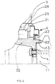
- the outer ring 1 of a ball bearing is in one piece with one extending radially outward Provided flange.
- a flange 4 is formed, which extends radially inwards extends.
- the flange 2 of the bearing outer ring 1 and the flange 4 of the bearing inner ring 3 are along their circumference with mounting holes provided by which the bearing outer ring 1 by means of Hexagon screws 8 on the housing 9 of the drive motor of an electric locomotive and the bearing inner ring 3 using hexagon screws 10 on the end face the drive shaft 11 of the traction motor is attached. Expansion screws can also be used for fastening his.
- the drive shaft 11 is with a cylindrical approach 12 provided by the bore 13 of the flange 4 is added and the centering of the bearing inner ring 3 serves.
- the bearing outer ring 1 is a relatively short Fitting surface 15 in the bore 16 of the motor housing 9 centered.
- a blind bore 17 serves as a receptacle for a temperature sensor that tight until this way to the track 18 of the ball row 7 to be monitored can be introduced.
- Both end faces of the bearing outer ring 1 have Turns into which the substantially U-shaped outer sealing ring elements 19, 20 of the labyrinth seals 5, 6 are used.
- the attachment takes place e.g. B. in a known manner in that one on the outside Edge of the nose (or bulge) bent out Sealing ring element in an annular groove 21 in the recess of the bearing ring 1 snaps into place.
- an adhesive can also be used.
- the labyrinth seal 5 on the left in the figure is still as a carrier for a rotation and speed measuring device designed.
- a pulse generator ring 24 is arranged in a known manner, the z. B. a succession along its circumference has oppositely magnetized zones.
- a sensor 25 is located in the outer sealing ring element 19 attached, which moved past him with rotating shaft 11 can scan magnetized zones and corresponding signals to an electronic device delivers.
- Other embodiments of pulser rings and sensors can of course be compared Way are used.
- FIG. 2 shows an arrangement with a cylindrical roller bearing, which essentially according to the embodiment Figure 1 corresponds.
- the bearing inner ring 32 has on the side of it Flange an annular projection 33, the Bore the centering of the bearing inner ring 32 the drive shaft 11 is used.
Landscapes
- Engineering & Computer Science (AREA)
- General Engineering & Computer Science (AREA)
- Mechanical Engineering (AREA)
- Power Engineering (AREA)
- Transportation (AREA)
- Rolling Contact Bearings (AREA)
- Arrangement Or Mounting Of Propulsion Units For Vehicles (AREA)
- Arrangement And Driving Of Transmission Devices (AREA)
- Mounting Of Bearings Or Others (AREA)
- Sealing Of Bearings (AREA)
- Motor Power Transmission Devices (AREA)
- Golf Clubs (AREA)
- Load-Engaging Elements For Cranes (AREA)
- Chair Legs, Seat Parts, And Backrests (AREA)
Description
- Figur 1
- die endseitige Lagerung der Antriebswelle eines Fahrmotors eines elektrischen Triebfahrzeuges und
- Figur 2
- eine weitere Ausführungsvariante der Anordnung.
Claims (4)
- Anordnung zur endseitigen Lagerung einer Welle oder Achse in einem Tragteil, nämlich der Antriebswelle eines Fahrmotors elektrischer Triebfahrzeuge im Motorgehäuse, mit einem Lagerinnen- (3, 32) und einem Lageraußenring (1, 29), zwischen denen eine Wälzkörperreihe (7, 31) angeordnet ist, wobei der Zwischenraum durch eine Dichtung (5, 6) abgedichtet ist und wobei der Lageraußenring (1, 29) mit einer zylindrischen Zentrierfläche (15) zur zentrischen Führung in einer entsprechenden Bohrung des Tragteils (9) und der Lagerinnenring (3, 32) mit einer zylindrischen Zentrierfläche (13) zur zentrischen Führung auf einem entsprechenden Abschnitt der Welle oder Achse (11) versehen sind, dadurch gekennzeichnet, daß der Lageraußenring (1, 29) Bohrungen zur Schraubbefestigung am Tragteil (9) und der Lagerinnenring (3, 32) einen radial nach innen gerichteten Flansch (4) zur Schraubbefestigung an der Stirnseite der Welle oder Achse (11) aufweist und daß der Lageraußenring (1, 29) einstückig mit einem radial nach außen gerichteten Flansch (2) ausgeführt ist, wobei beide Flansche (2, 4) mit durchgehenden Bohrungen zur Schraubbefestigung von außen an den an einer der Lagerseiten angeordneten Endflächen von Welle (11) und Tragteil (9) versehen sind.
- Anordnung nach Anspruch 1, dadurch gekennzeichnet, daß die Flanschfläche die Endfläche des Lagerinnenringes (3, 32) bildet oder in deren Nähe liegt und der Lagerinnenring (3, 32) eine kegelige Bohrung (26) aufweist, so daß er einen vom Flansch (4) ausgehenden Träger gleicher Festigkeit bildet.
- Anordnung nach Anspruch 1 oder 2, dadurch gekennzeichnet, daß auf beiden Seiten des Lagers Dichtungen angeordnet sind und eine der Dichtungen (5, 6) mit einem Impulsgeber (24) zur Umdrehungs- und Geschwindigkeitsmessung versehen ist.
- Anordnung nach einem der vorhergehenden Ansprüche, dadurch gekennzeichnet, daß der Lageraußenring (1, 29) eine bis nahe an die Wälzkörperlaufbahn heranreichende Aufnahme (17) für einen Thermofiihler aufweist.
Priority Applications (6)
| Application Number | Priority Date | Filing Date | Title |
|---|---|---|---|
| EP93104990A EP0617208B2 (de) | 1993-03-26 | 1993-03-26 | Anordnung zur Lagerung einer Welle oder Achse in einem Tragteil |
| AT93104990T ATE159797T1 (de) | 1993-03-26 | 1993-03-26 | Anordnung zur lagerung einer welle oder achse in einem tragteil |
| ES93104990T ES2108153T5 (es) | 1993-03-26 | 1993-03-26 | Disposicion para el apoyo de un arbol o eje en una parte de soporte. |
| DE59307607T DE59307607D1 (de) | 1993-03-26 | 1993-03-26 | Anordnung zur Lagerung einer Welle oder Achse in einem Tragteil |
| US08/216,804 US5468072A (en) | 1993-03-26 | 1994-03-23 | System and method for supporting a shaft or axle in a support component |
| JP07780894A JP3569309B2 (ja) | 1993-03-26 | 1994-03-25 | 軸あるいは車軸を支持部内に支持するための軸受装置 |
Applications Claiming Priority (1)
| Application Number | Priority Date | Filing Date | Title |
|---|---|---|---|
| EP93104990A EP0617208B2 (de) | 1993-03-26 | 1993-03-26 | Anordnung zur Lagerung einer Welle oder Achse in einem Tragteil |
Publications (3)
| Publication Number | Publication Date |
|---|---|
| EP0617208A1 EP0617208A1 (de) | 1994-09-28 |
| EP0617208B1 EP0617208B1 (de) | 1997-10-29 |
| EP0617208B2 true EP0617208B2 (de) | 2001-01-17 |
Family
ID=8212740
Family Applications (1)
| Application Number | Title | Priority Date | Filing Date |
|---|---|---|---|
| EP93104990A Expired - Lifetime EP0617208B2 (de) | 1993-03-26 | 1993-03-26 | Anordnung zur Lagerung einer Welle oder Achse in einem Tragteil |
Country Status (6)
| Country | Link |
|---|---|
| US (1) | US5468072A (de) |
| EP (1) | EP0617208B2 (de) |
| JP (1) | JP3569309B2 (de) |
| AT (1) | ATE159797T1 (de) |
| DE (1) | DE59307607D1 (de) |
| ES (1) | ES2108153T5 (de) |
Families Citing this family (18)
| Publication number | Priority date | Publication date | Assignee | Title |
|---|---|---|---|---|
| SE507951C2 (sv) * | 1994-11-28 | 1998-08-03 | Skf Ab | Lagringsanordning för stora radiella laster kring en förhållandevis tunnväggig röraxel |
| US5746452A (en) * | 1995-03-29 | 1998-05-05 | Reliance Electric Industrial Company | Bearing assembly having integrated speed sensor |
| DE19640895B4 (de) * | 1996-10-04 | 2007-07-12 | Schaeffler Kg | Wälzlager mit einer integrierten Drehzahlmeßeinrichtung |
| US5954186A (en) * | 1996-12-11 | 1999-09-21 | Precision, Inc. | Speed monitoring idler roller for conveyors |
| DE19805566B4 (de) * | 1998-02-12 | 2006-07-20 | Schaeffler Kg | Wälzlagerung für Schienenfahrzeuge mit Stromdurchgang |
| FR2791103B1 (fr) * | 1999-03-17 | 2001-04-13 | Skf France | Palier a roulement instrumente |
| JP2002130263A (ja) * | 2000-10-31 | 2002-05-09 | Ntn Corp | 温度センサ付き軸受 |
| US7077662B2 (en) * | 2002-01-15 | 2006-07-18 | Tribotek, Inc. | Contact woven connectors |
| DE10359646A1 (de) * | 2003-12-18 | 2005-07-28 | Fag Kugelfischer Ag | Radlager in einem Radträger |
| FR2884979B1 (fr) * | 2005-04-22 | 2007-07-20 | Snr Roulements Sa | Alternateur comprenant un roulement a bride de fixation |
| JP2008045592A (ja) * | 2006-08-11 | 2008-02-28 | Jtekt Corp | ピニオン軸支持装置及びピニオンユニット軸受 |
| DE102006045178A1 (de) * | 2006-09-25 | 2008-04-03 | Siemens Ag | Elektrische Maschine |
| JP2008032230A (ja) * | 2007-10-01 | 2008-02-14 | Nsk Ltd | センサ付軸受装置 |
| JP5321115B2 (ja) * | 2009-02-17 | 2013-10-23 | 日本精工株式会社 | 回転センサ付き転がり軸受 |
| JP5533027B2 (ja) * | 2010-02-26 | 2014-06-25 | 日本精工株式会社 | センサ付き軸受及び機械装置 |
| CN106438721B (zh) * | 2016-11-18 | 2018-04-24 | 广西大学 | 一种可调过盈量的轴承座 |
| DE102016223910A1 (de) * | 2016-12-01 | 2017-03-02 | Audi Ag | Radlageranordnung für ein Kraftfahrzeug |
| CN113446322B (zh) * | 2021-07-26 | 2022-06-14 | 太原重工股份有限公司 | 油膜轴承的端罩箱盖装置 |
Citations (4)
| Publication number | Priority date | Publication date | Assignee | Title |
|---|---|---|---|---|
| DE704790C (de) † | 1940-04-04 | 1941-04-07 | Kloeckner Werke Akt Ges | Kugellenkkranz fuer Fahrzeuge und Anhaenger aller Art |
| DE1834297U (de) † | 1961-04-17 | 1961-07-06 | Rothe Erde Eisenwerk | Kugellenkkranz. |
| DE3234443A1 (de) † | 1982-01-18 | 1983-07-21 | VEB Werkzeugmaschinenkombinat "Fritz Heckert" Karl-Marx-Stadt, DDR 9030 Karl-Marx-Stadt | Einrichtung zum erfassen thermisch wirksamer zustandsaenderungen in lagern |
| EP0323789B1 (de) † | 1988-01-08 | 1991-10-16 | S.N.R. Roulements | Radnabe von Kraftfahrzeugen |
Family Cites Families (8)
| Publication number | Priority date | Publication date | Assignee | Title |
|---|---|---|---|---|
| NL169630C (nl) * | 1972-04-18 | 1982-08-02 | Skf Ind Trading & Dev | Uitwisselbare lagereenheid. |
| JPS59163225U (ja) * | 1983-04-18 | 1984-11-01 | 三菱電機株式会社 | ころがり軸受装置 |
| DE3615871A1 (de) * | 1986-05-10 | 1987-11-12 | Hoesch Ag | Mittenfreies grosswaelzlager mit integriertem elektrischem direktantrieb |
| DE3721737A1 (de) * | 1987-07-01 | 1989-01-12 | Porsche Ag | Lagervorrichtung fuer ein kraftfahrzeugrad |
| DE3902141A1 (de) * | 1989-01-25 | 1990-08-09 | Kugelfischer G Schaefer & Co | Radlagerung |
| DE3907105C2 (de) * | 1989-03-04 | 1993-11-18 | Kugelfischer G Schaefer & Co | Radlagerung für angetriebene Räder |
| DE3920299A1 (de) * | 1989-06-21 | 1991-01-03 | Kugelfischer G Schaefer & Co | Radlagerung fuer kraftfahrzeuge |
| US5209701A (en) * | 1990-12-07 | 1993-05-11 | Nikon Corporation | Hub unit bearing apparatus with improved pre-loading arrangement |
-
1993
- 1993-03-26 ES ES93104990T patent/ES2108153T5/es not_active Expired - Lifetime
- 1993-03-26 AT AT93104990T patent/ATE159797T1/de active
- 1993-03-26 EP EP93104990A patent/EP0617208B2/de not_active Expired - Lifetime
- 1993-03-26 DE DE59307607T patent/DE59307607D1/de not_active Expired - Lifetime
-
1994
- 1994-03-23 US US08/216,804 patent/US5468072A/en not_active Expired - Lifetime
- 1994-03-25 JP JP07780894A patent/JP3569309B2/ja not_active Expired - Lifetime
Patent Citations (4)
| Publication number | Priority date | Publication date | Assignee | Title |
|---|---|---|---|---|
| DE704790C (de) † | 1940-04-04 | 1941-04-07 | Kloeckner Werke Akt Ges | Kugellenkkranz fuer Fahrzeuge und Anhaenger aller Art |
| DE1834297U (de) † | 1961-04-17 | 1961-07-06 | Rothe Erde Eisenwerk | Kugellenkkranz. |
| DE3234443A1 (de) † | 1982-01-18 | 1983-07-21 | VEB Werkzeugmaschinenkombinat "Fritz Heckert" Karl-Marx-Stadt, DDR 9030 Karl-Marx-Stadt | Einrichtung zum erfassen thermisch wirksamer zustandsaenderungen in lagern |
| EP0323789B1 (de) † | 1988-01-08 | 1991-10-16 | S.N.R. Roulements | Radnabe von Kraftfahrzeugen |
Non-Patent Citations (2)
| Title |
|---|
| A. KÖTTRITSCH: "WÄLZLAGER", SEITEN 268, 269 † |
| INA-KATALOG 403, "DREHVERBINDUNGEN", SEITEN 40,41 † |
Also Published As
| Publication number | Publication date |
|---|---|
| ATE159797T1 (de) | 1997-11-15 |
| DE59307607D1 (de) | 1997-12-04 |
| EP0617208B1 (de) | 1997-10-29 |
| JP3569309B2 (ja) | 2004-09-22 |
| ES2108153T3 (es) | 1997-12-16 |
| ES2108153T5 (es) | 2001-03-01 |
| US5468072A (en) | 1995-11-21 |
| JPH06300046A (ja) | 1994-10-25 |
| EP0617208A1 (de) | 1994-09-28 |
Similar Documents
| Publication | Publication Date | Title |
|---|---|---|
| EP0617208B1 (de) | Anordnung zur Lagerung einer Welle oder Achse in einem Tragteil | |
| DE69108688T2 (de) | Ausgleichsgetriebeeinheit mit schwimmenden Tellerrad. | |
| DE69308430T2 (de) | Zentrifuge mit Rotorantriebsachse mit einer elastischen Dämpferverbindung | |
| DE69503562T2 (de) | Lagereinheit für Fahrzeugrad | |
| DE3014446A1 (de) | Waelzlager mit doppelreihig angeordneten waelzelementen und vorrichtung zur montage von fahrzeugraedern | |
| DE2329554A1 (de) | Lageranordnung fuer eine antreibbare radnabe eines motorfahrzeugs | |
| DE2248012A1 (de) | Mit befestigungsflanschen versehenes waelzlager | |
| EP3524838B1 (de) | Abgedichtetes lagermodul | |
| DE2105123A1 (de) | Kraftfahrzeug Radlagersatz | |
| DE102007049087A1 (de) | Radial- und axial belastbares Wälzlager | |
| DE3138366C2 (de) | ||
| DE4033592C2 (de) | ||
| EP0379490B1 (de) | Anordnung eines kegeltriebes in einem getriebegehäuse | |
| DE2355821B2 (de) | Lagereinheit | |
| EP0816127B1 (de) | Radlagerung einer angetriebenen Achse mit einem hohlen, die Radlasten aufnehmenden Achskörper | |
| EP3581830A1 (de) | Getriebeanordnung | |
| WO2025185888A1 (de) | Radträgeranordnung für ein kraftfahrzeug | |
| DE19832073A1 (de) | Radhalterung eines Fahrzeugs | |
| DE2549212C2 (de) | Fühleinrichtung für die Drehgeschwindigkeit eines Rades | |
| EP4226485A1 (de) | Elektrische maschine mit einer lagerung einer mit einem rotor verbundenen verbindungswelle | |
| DE9304615U1 (de) | Anordnung zur Lagerung einer Welle oder Achse in einem Tragteil | |
| DE102008051613A1 (de) | Fräskopf | |
| DE102015220368A1 (de) | Schutzelement für eine Radlagereinheit | |
| DE102015211455A1 (de) | Radmodul für eine angetriebene Achse eines Kraftfahrzeugs | |
| DE3816732C2 (de) |
Legal Events
| Date | Code | Title | Description |
|---|---|---|---|
| PUAI | Public reference made under article 153(3) epc to a published international application that has entered the european phase |
Free format text: ORIGINAL CODE: 0009012 |
|
| AK | Designated contracting states |
Kind code of ref document: A1 Designated state(s): AT CH DE ES FR GB IT LI SE |
|
| 17P | Request for examination filed |
Effective date: 19941108 |
|
| R17P | Request for examination filed (corrected) |
Effective date: 19941108 |
|
| 17Q | First examination report despatched |
Effective date: 19950530 |
|
| GRAG | Despatch of communication of intention to grant |
Free format text: ORIGINAL CODE: EPIDOS AGRA |
|
| GRAH | Despatch of communication of intention to grant a patent |
Free format text: ORIGINAL CODE: EPIDOS IGRA |
|
| GRAH | Despatch of communication of intention to grant a patent |
Free format text: ORIGINAL CODE: EPIDOS IGRA |
|
| GRAA | (expected) grant |
Free format text: ORIGINAL CODE: 0009210 |
|
| AK | Designated contracting states |
Kind code of ref document: B1 Designated state(s): AT CH DE ES FR GB IT LI SE |
|
| REF | Corresponds to: |
Ref document number: 159797 Country of ref document: AT Date of ref document: 19971115 Kind code of ref document: T |
|
| REG | Reference to a national code |
Ref country code: CH Ref legal event code: EP |
|
| ET | Fr: translation filed | ||
| GBT | Gb: translation of ep patent filed (gb section 77(6)(a)/1977) |
Effective date: 19971031 |
|
| REF | Corresponds to: |
Ref document number: 59307607 Country of ref document: DE Date of ref document: 19971204 |
|
| REG | Reference to a national code |
Ref country code: ES Ref legal event code: FG2A Ref document number: 2108153 Country of ref document: ES Kind code of ref document: T3 |
|
| ITF | It: translation for a ep patent filed | ||
| PLBI | Opposition filed |
Free format text: ORIGINAL CODE: 0009260 |
|
| 26 | Opposition filed |
Opponent name: INA WAELZLAGER SCHAEFFER OHG Effective date: 19980507 |
|
| PLAV | Examination of admissibility of opposition |
Free format text: ORIGINAL CODE: EPIDOS OPEX |
|
| PLBI | Opposition filed |
Free format text: ORIGINAL CODE: 0009260 |
|
| PLAV | Examination of admissibility of opposition |
Free format text: ORIGINAL CODE: EPIDOS OPEX |
|
| PLBF | Reply of patent proprietor to notice(s) of opposition |
Free format text: ORIGINAL CODE: EPIDOS OBSO |
|
| 26 | Opposition filed |
Opponent name: FAG KUGELFISCHER GEORG SCHAEFER AKTIENGESELLSCHAFT Effective date: 19980729 Opponent name: INA WAELZLAGER SCHAEFFER OHG Effective date: 19980507 |
|
| PLBF | Reply of patent proprietor to notice(s) of opposition |
Free format text: ORIGINAL CODE: EPIDOS OBSO |
|
| PLAW | Interlocutory decision in opposition |
Free format text: ORIGINAL CODE: EPIDOS IDOP |
|
| PLAW | Interlocutory decision in opposition |
Free format text: ORIGINAL CODE: EPIDOS IDOP |
|
| PUAH | Patent maintained in amended form |
Free format text: ORIGINAL CODE: 0009272 |
|
| 27A | Patent maintained in amended form |
Effective date: 20010117 |
|
| AK | Designated contracting states |
Kind code of ref document: B2 Designated state(s): AT CH DE ES FR GB IT LI SE |
|
| GBTA | Gb: translation of amended ep patent filed (gb section 77(6)(b)/1977) | ||
| REG | Reference to a national code |
Ref country code: CH Ref legal event code: AEN Free format text: AUFRECHTERHALTUNG DES PATENTES IN GEAENDERTER FORM |
|
| ET3 | Fr: translation filed ** decision concerning opposition | ||
| REG | Reference to a national code |
Ref country code: ES Ref legal event code: DC2A Kind code of ref document: T5 Effective date: 20010205 |
|
| ITF | It: translation for a ep patent filed | ||
| REG | Reference to a national code |
Ref country code: GB Ref legal event code: IF02 |
|
| PGFP | Annual fee paid to national office [announced via postgrant information from national office to epo] |
Ref country code: FR Payment date: 20120406 Year of fee payment: 20 Ref country code: CH Payment date: 20120326 Year of fee payment: 20 |
|
| PGFP | Annual fee paid to national office [announced via postgrant information from national office to epo] |
Ref country code: SE Payment date: 20120328 Year of fee payment: 20 Ref country code: GB Payment date: 20120326 Year of fee payment: 20 Ref country code: IT Payment date: 20120327 Year of fee payment: 20 |
|
| PGFP | Annual fee paid to national office [announced via postgrant information from national office to epo] |
Ref country code: DE Payment date: 20120328 Year of fee payment: 20 |
|
| REG | Reference to a national code |
Ref country code: DE Ref legal event code: R071 Ref document number: 59307607 Country of ref document: DE |
|
| PGFP | Annual fee paid to national office [announced via postgrant information from national office to epo] |
Ref country code: AT Payment date: 20120302 Year of fee payment: 20 |
|
| REG | Reference to a national code |
Ref country code: CH Ref legal event code: PL |
|
| REG | Reference to a national code |
Ref country code: GB Ref legal event code: PE20 Expiry date: 20130325 |
|
| PG25 | Lapsed in a contracting state [announced via postgrant information from national office to epo] |
Ref country code: DE Free format text: LAPSE BECAUSE OF EXPIRATION OF PROTECTION Effective date: 20130327 Ref country code: GB Free format text: LAPSE BECAUSE OF EXPIRATION OF PROTECTION Effective date: 20130325 |
|
| REG | Reference to a national code |
Ref country code: SE Ref legal event code: EUG |
|
| REG | Reference to a national code |
Ref country code: AT Ref legal event code: MK07 Ref document number: 159797 Country of ref document: AT Kind code of ref document: T Effective date: 20130326 |
|
| PGFP | Annual fee paid to national office [announced via postgrant information from national office to epo] |
Ref country code: ES Payment date: 20120326 Year of fee payment: 20 |
|
| REG | Reference to a national code |
Ref country code: ES Ref legal event code: FD2A Effective date: 20130718 |
|
| PG25 | Lapsed in a contracting state [announced via postgrant information from national office to epo] |
Ref country code: ES Free format text: LAPSE BECAUSE OF EXPIRATION OF PROTECTION Effective date: 20130327 |