EP0609380B1 - Raccords pour equipements hydrauliques - Google Patents
Raccords pour equipements hydrauliques Download PDFInfo
- Publication number
- EP0609380B1 EP0609380B1 EP92923261A EP92923261A EP0609380B1 EP 0609380 B1 EP0609380 B1 EP 0609380B1 EP 92923261 A EP92923261 A EP 92923261A EP 92923261 A EP92923261 A EP 92923261A EP 0609380 B1 EP0609380 B1 EP 0609380B1
- Authority
- EP
- European Patent Office
- Prior art keywords
- port
- tapered surface
- tube
- lip
- hydraulic coupling
- Prior art date
- Legal status (The legal status is an assumption and is not a legal conclusion. Google has not performed a legal analysis and makes no representation as to the accuracy of the status listed.)
- Expired - Lifetime
Links
- 230000008878 coupling Effects 0.000 claims abstract description 64
- 238000010168 coupling process Methods 0.000 claims abstract description 64
- 238000005859 coupling reaction Methods 0.000 claims abstract description 64
- 239000011347 resin Substances 0.000 claims abstract description 20
- 229920005989 resin Polymers 0.000 claims abstract description 20
- 239000012530 fluid Substances 0.000 claims abstract description 6
- 238000007789 sealing Methods 0.000 claims description 31
- 239000000463 material Substances 0.000 claims description 16
- 230000006835 compression Effects 0.000 claims description 15
- 238000007906 compression Methods 0.000 claims description 15
- 230000000295 complement effect Effects 0.000 claims description 7
- 238000004891 communication Methods 0.000 claims description 6
- 230000013011 mating Effects 0.000 claims description 6
- 239000007769 metal material Substances 0.000 claims description 2
- 239000002861 polymer material Substances 0.000 claims 2
- 239000002184 metal Substances 0.000 abstract description 18
- 229910052751 metal Inorganic materials 0.000 abstract description 18
- 229920000642 polymer Polymers 0.000 abstract description 18
- 241000538562 Banjos Species 0.000 abstract description 2
- 239000004033 plastic Substances 0.000 description 6
- 229920003023 plastic Polymers 0.000 description 6
- 239000011324 bead Substances 0.000 description 5
- 239000003507 refrigerant Substances 0.000 description 5
- 230000007774 longterm Effects 0.000 description 4
- 238000004378 air conditioning Methods 0.000 description 3
- 238000010438 heat treatment Methods 0.000 description 3
- 238000000034 method Methods 0.000 description 3
- 229910001369 Brass Inorganic materials 0.000 description 2
- 229910001209 Low-carbon steel Inorganic materials 0.000 description 2
- RTAQQCXQSZGOHL-UHFFFAOYSA-N Titanium Chemical compound [Ti] RTAQQCXQSZGOHL-UHFFFAOYSA-N 0.000 description 2
- 230000001154 acute effect Effects 0.000 description 2
- 229910045601 alloy Inorganic materials 0.000 description 2
- 239000000956 alloy Substances 0.000 description 2
- 229910052782 aluminium Inorganic materials 0.000 description 2
- XAGFODPZIPBFFR-UHFFFAOYSA-N aluminium Chemical compound [Al] XAGFODPZIPBFFR-UHFFFAOYSA-N 0.000 description 2
- 239000010951 brass Substances 0.000 description 2
- 238000001816 cooling Methods 0.000 description 2
- 230000014759 maintenance of location Effects 0.000 description 2
- 238000004519 manufacturing process Methods 0.000 description 2
- 150000002739 metals Chemical class 0.000 description 2
- 239000000203 mixture Substances 0.000 description 2
- 239000010935 stainless steel Substances 0.000 description 2
- 229910001220 stainless steel Inorganic materials 0.000 description 2
- 239000010936 titanium Substances 0.000 description 2
- 229910052719 titanium Inorganic materials 0.000 description 2
- 230000007704 transition Effects 0.000 description 2
- RYGMFSIKBFXOCR-UHFFFAOYSA-N Copper Chemical compound [Cu] RYGMFSIKBFXOCR-UHFFFAOYSA-N 0.000 description 1
- 229910000792 Monel Inorganic materials 0.000 description 1
- 239000004809 Teflon Substances 0.000 description 1
- 229920006362 Teflon® Polymers 0.000 description 1
- 238000004458 analytical method Methods 0.000 description 1
- 230000015572 biosynthetic process Effects 0.000 description 1
- 239000010949 copper Substances 0.000 description 1
- 229910052802 copper Inorganic materials 0.000 description 1
- 238000005336 cracking Methods 0.000 description 1
- 230000000694 effects Effects 0.000 description 1
- 230000005489 elastic deformation Effects 0.000 description 1
- 239000013013 elastic material Substances 0.000 description 1
- 238000005516 engineering process Methods 0.000 description 1
- 230000002708 enhancing effect Effects 0.000 description 1
- 230000007613 environmental effect Effects 0.000 description 1
- 230000006870 function Effects 0.000 description 1
- 230000002452 interceptive effect Effects 0.000 description 1
- 230000007246 mechanism Effects 0.000 description 1
- 230000008569 process Effects 0.000 description 1
- 230000004044 response Effects 0.000 description 1
- 239000007779 soft material Substances 0.000 description 1
- 239000000126 substance Substances 0.000 description 1
- BFKJFAAPBSQJPD-UHFFFAOYSA-N tetrafluoroethene Chemical compound FC(F)=C(F)F BFKJFAAPBSQJPD-UHFFFAOYSA-N 0.000 description 1
Images


Classifications
-
- F—MECHANICAL ENGINEERING; LIGHTING; HEATING; WEAPONS; BLASTING
- F16—ENGINEERING ELEMENTS AND UNITS; GENERAL MEASURES FOR PRODUCING AND MAINTAINING EFFECTIVE FUNCTIONING OF MACHINES OR INSTALLATIONS; THERMAL INSULATION IN GENERAL
- F16L—PIPES; JOINTS OR FITTINGS FOR PIPES; SUPPORTS FOR PIPES, CABLES OR PROTECTIVE TUBING; MEANS FOR THERMAL INSULATION IN GENERAL
- F16L13/00—Non-disconnectible pipe-joints, e.g. soldered, adhesive or caulked joints
- F16L13/14—Non-disconnectible pipe-joints, e.g. soldered, adhesive or caulked joints made by plastically deforming the material of the pipe, e.g. by flanging, rolling
- F16L13/16—Non-disconnectible pipe-joints, e.g. soldered, adhesive or caulked joints made by plastically deforming the material of the pipe, e.g. by flanging, rolling the pipe joint consisting of overlapping extremities having mutually co-operating collars
- F16L13/165—Non-disconnectible pipe-joints, e.g. soldered, adhesive or caulked joints made by plastically deforming the material of the pipe, e.g. by flanging, rolling the pipe joint consisting of overlapping extremities having mutually co-operating collars the pipe or collar being deformed by an axially movable sleeve
-
- F—MECHANICAL ENGINEERING; LIGHTING; HEATING; WEAPONS; BLASTING
- F16—ENGINEERING ELEMENTS AND UNITS; GENERAL MEASURES FOR PRODUCING AND MAINTAINING EFFECTIVE FUNCTIONING OF MACHINES OR INSTALLATIONS; THERMAL INSULATION IN GENERAL
- F16L—PIPES; JOINTS OR FITTINGS FOR PIPES; SUPPORTS FOR PIPES, CABLES OR PROTECTIVE TUBING; MEANS FOR THERMAL INSULATION IN GENERAL
- F16L19/00—Joints in which sealing surfaces are pressed together by means of a member, e.g. a swivel nut, screwed on or into one of the joint parts
- F16L19/02—Pipe ends provided with collars or flanges, integral with the pipe or not, pressed together by a screwed member
- F16L19/0212—Pipe ends provided with collars or flanges, integral with the pipe or not, pressed together by a screwed member using specially adapted sealing means
-
- F—MECHANICAL ENGINEERING; LIGHTING; HEATING; WEAPONS; BLASTING
- F16—ENGINEERING ELEMENTS AND UNITS; GENERAL MEASURES FOR PRODUCING AND MAINTAINING EFFECTIVE FUNCTIONING OF MACHINES OR INSTALLATIONS; THERMAL INSULATION IN GENERAL
- F16L—PIPES; JOINTS OR FITTINGS FOR PIPES; SUPPORTS FOR PIPES, CABLES OR PROTECTIVE TUBING; MEANS FOR THERMAL INSULATION IN GENERAL
- F16L27/00—Adjustable joints, Joints allowing movement
- F16L27/08—Adjustable joints, Joints allowing movement allowing adjustment or movement only about the axis of one pipe
- F16L27/087—Joints with radial fluid passages
- F16L27/093—Joints with radial fluid passages of the "banjo" type, i.e. pivoting right-angle couplings
-
- F—MECHANICAL ENGINEERING; LIGHTING; HEATING; WEAPONS; BLASTING
- F16—ENGINEERING ELEMENTS AND UNITS; GENERAL MEASURES FOR PRODUCING AND MAINTAINING EFFECTIVE FUNCTIONING OF MACHINES OR INSTALLATIONS; THERMAL INSULATION IN GENERAL
- F16L—PIPES; JOINTS OR FITTINGS FOR PIPES; SUPPORTS FOR PIPES, CABLES OR PROTECTIVE TUBING; MEANS FOR THERMAL INSULATION IN GENERAL
- F16L41/00—Branching pipes; Joining pipes to walls
- F16L41/005—Branching pipes; Joining pipes to walls adjustable and comprising a hollow threaded part in an opening
-
- F—MECHANICAL ENGINEERING; LIGHTING; HEATING; WEAPONS; BLASTING
- F16—ENGINEERING ELEMENTS AND UNITS; GENERAL MEASURES FOR PRODUCING AND MAINTAINING EFFECTIVE FUNCTIONING OF MACHINES OR INSTALLATIONS; THERMAL INSULATION IN GENERAL
- F16L—PIPES; JOINTS OR FITTINGS FOR PIPES; SUPPORTS FOR PIPES, CABLES OR PROTECTIVE TUBING; MEANS FOR THERMAL INSULATION IN GENERAL
- F16L41/00—Branching pipes; Joining pipes to walls
- F16L41/08—Joining pipes to walls or pipes, the joined pipe axis being perpendicular to the plane of the wall or to the axis of another pipe
- F16L41/086—Joining pipes to walls or pipes, the joined pipe axis being perpendicular to the plane of the wall or to the axis of another pipe fixed with screws
-
- F—MECHANICAL ENGINEERING; LIGHTING; HEATING; WEAPONS; BLASTING
- F16—ENGINEERING ELEMENTS AND UNITS; GENERAL MEASURES FOR PRODUCING AND MAINTAINING EFFECTIVE FUNCTIONING OF MACHINES OR INSTALLATIONS; THERMAL INSULATION IN GENERAL
- F16L—PIPES; JOINTS OR FITTINGS FOR PIPES; SUPPORTS FOR PIPES, CABLES OR PROTECTIVE TUBING; MEANS FOR THERMAL INSULATION IN GENERAL
- F16L41/00—Branching pipes; Joining pipes to walls
- F16L41/08—Joining pipes to walls or pipes, the joined pipe axis being perpendicular to the plane of the wall or to the axis of another pipe
- F16L41/10—Joining pipes to walls or pipes, the joined pipe axis being perpendicular to the plane of the wall or to the axis of another pipe the extremity of the pipe being screwed into the wall
-
- Y—GENERAL TAGGING OF NEW TECHNOLOGICAL DEVELOPMENTS; GENERAL TAGGING OF CROSS-SECTIONAL TECHNOLOGIES SPANNING OVER SEVERAL SECTIONS OF THE IPC; TECHNICAL SUBJECTS COVERED BY FORMER USPC CROSS-REFERENCE ART COLLECTIONS [XRACs] AND DIGESTS
- Y10—TECHNICAL SUBJECTS COVERED BY FORMER USPC
- Y10S—TECHNICAL SUBJECTS COVERED BY FORMER USPC CROSS-REFERENCE ART COLLECTIONS [XRACs] AND DIGESTS
- Y10S285/00—Pipe joints or couplings
- Y10S285/901—Cap closures
-
- Y—GENERAL TAGGING OF NEW TECHNOLOGICAL DEVELOPMENTS; GENERAL TAGGING OF CROSS-SECTIONAL TECHNOLOGIES SPANNING OVER SEVERAL SECTIONS OF THE IPC; TECHNICAL SUBJECTS COVERED BY FORMER USPC CROSS-REFERENCE ART COLLECTIONS [XRACs] AND DIGESTS
- Y10—TECHNICAL SUBJECTS COVERED BY FORMER USPC
- Y10S—TECHNICAL SUBJECTS COVERED BY FORMER USPC CROSS-REFERENCE ART COLLECTIONS [XRACs] AND DIGESTS
- Y10S285/00—Pipe joints or couplings
- Y10S285/906—Equivalents
Definitions
- the present invention relates to hydraulic couplings. More specifically, the field of the invention is that of hydraulic port fittings such as used in automobiles, aircraft, and the like.
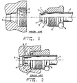
- the prior art tube-to-port fitting as shown in Figure 1, comprises a tube 1 which includes a raised bead 2 which sits behind reduced diameter portion 3. This diameter 3 is required to be of very smooth surface finish. Often, the tube-to-port fitting also includes an o-ring retention feature 4. The periphery of bead 2 is severely stressed during the formation process, and these stresses can lead to cracking, though proper specification of tubing composition may ameliorate this problem. However, specification of required chemical composition, heat treatment, hardness, wall thickness, or specific manufacturing methods for the tubing further adds to the expense of the fitting.
- Tube 1 is assembled to a mating port 5 with tube nut 6.
- the port 5 has a very finely machined internal configuration which is required to have a fine surface finish in order to seal reliably.
- Another problem involves the orientation of the o-ring. Positioned in both the tapered area and the parallel interface, the o-ring is deformed during the assembly operation into a kidney-like shape, with a portion remaining in the relatively large tapered portion of the port. When the o-ring takes a set over time, it will be incapable of movement within the pocket, being trapped by the tapered portion. In order for an o-ring to work properly, it must be capable of moving in response to pressure differentials. Therefore, the improper positioning of the o-ring in the port interface tends to prevent the o-ring from moving and thus degrades long term performance of the fitting.
- a further need is for an improved hydraulic coupling which includes secondary seals.
- the elastic deformation of mating components is preferred because the elastic memory of the material (either metal or rubber and the like) imparts a continuous sealing force. In comparison, plastic deformation of the material, which permanently deforms the fitting components, imparts no additional sealing force. Both metals and rubber type materials are subject to both forms of deformation, as metal material may be plasticly deformed by high torque when assembled while elastic materials may be plasticly deformed by setting over time.
- Embodiments of the present invention impart multiple seals to the port interface, and use elastic memory of metallic components in the interface where possible. This is attained by the use of elastic components in those instances where such is possible or desireable in conjunction with abutting tapered metallic surfaces which allow for the generation of an interface the integrity of which is enhanced by elastic memory. With ports made of softer materials, a metallic component having a complementary taper or a resin polymer component may be used to create a contact seal of similar integrity.
- the acute tapered metallic surfaces provides a high unit loading which ameliorates the need for the expensive materials needed for receiving the high torques required with prior art fitting components.
- GB-A-2207722 discloses a hydraulic coupling comprising a port including an opening, a portion defining a passageway in communication with said opening, an internally threaded portion in communication with said passageway, and a tapered surface facing said opening; conduit means for providing fluid communication to said port, said conduit means including a lip which deforms into sealing contact with said tapered surface of said port; and connector means for sealingly securing said conduit means to said port, said connector means including a rim and an externally threaded portion which is arranged to engage said internally threaded portion of said port and by threaded engagement force said lip into sealing contact with said tapered surface of said port and, according to the present invention, such a coupling is characterised in that said rim also deforms separately from said lip into sealing contact with said tapered surface by force produced by said threaded engagement.
- One embodiment involves a modified tube-to-port fitting system.
- This system requires a special port which is internally threaded to receive a tube nut.
- At the base of the port is a taper of a relatively acute angle.
- Similar ports currently exist, though they tend to be much more complicated than the port of this design.
- This port may be made simply by using a form drill to impart its thread minor diameter and the taper at the same time, no special surface finishes are required. The taper starts at the threaded minor diameter and progressively reduces inwardly. There are no complicated features or tight dimensional/surface finish requirements.
- a formed tube and tube nut is assembled into the port.
- This assembly does not comprise a beaded tube, but makes use of an expanded tube end which may include a lip for o-ring retention.
- the nut includes a shoulder which abuts the expanded tube end and drives it into the port, forcing the lip into the tapered surface of the port.
- This lip may also serve another purpose, and that is to prevent sealing during hand-tight assembly of components. Without this lip interfering with the tapered seat in the port during hand tight assembly of components, prior to torquing of components with wrenches, the o-ring would seal, and the fact that assembly torques had not been applied to create the metal-to-metal seal would not be obvious.
- the lip By wrench tightening the nut, the lip is driven into sealing engagement with the tapered surface to form a primary metal-to-metal seal.
- the lip may be formed with a complementary taper to facilitate creation of the primary metal-to-metal seal.
- the nut of the coupling has a thin-walled leading portion that conforms with the seat at the bottom of the port during assembly to create a metal-to-metal seal both with the taper of the port and with the outside of the expanded portion of the tube.
- a resin polymer ring may be substituted for the leading portion of the nut to create a contact seal both with the taper of the port and with the outside of the expanded portion of the tube.
- an o-ring may be placed on the expanded portion of tube in front of the thin-walled section of the tube nut, with the o-ring contacting the expanded portion of tube and the taper in the port during assembly, but which is not crushed as a gasket in the assembly.
- the lip contacts the taper of the port prior to the thin-walled portion of the tube nut making contact with the taper during assembly.
- the o-ring is placed on the expanded portion of tube, between the lip at the leading end, and the thin-walled portion of the tube nut, such that when assembled the o-ring is not compressed, but is in contact with the expanded portion of tube, the port taper, and the leading end of the thin-walled portion of the tube nut.
- the invention also includes an embodiment wherein the port includes another tube and a receiving nut, providing an improved tube to tube coupling.
- the present invention relates to hydraulic couplings, and particularly to couplings which utilize the elastic properties of materials, for example metals or o-rings, to form sealing contact between mating components.
- a first embodiment of the present invention is the tube-to-port coupling shown in Figures 3-5.
- Tube nut 204 is disposed over expanded portion 207 of tube 203 and includes an end having a relatively thin wall or rim 208.
- shoulder portion 211 of nut 203 abuts transition portion 210 of tube 203.
- Thin wall 208 may include a taper to match tapered surface 215 of port 201, although such a taper is not necessary to practice the present invention.
- Thin wall 208 of nut 204 is designed to conform with tapered surface 215 at the bottom of port 201 during assembly, and impinges on the outside of expanded portion 207 of tube 203.
- o-ring 209 may be included for additional sealing security where desired.
- o-rings are not acceptable components in hydraulic or gas systems, and the coupling functions properly either with or without o-ring 209. Where no such restriction on the use of o-rings exists, then the use of o-ring 209 will render the assembly even more reliable in the long term.
- Tube nut 204 is connected to port 201 by the engagement of external threads 205 of nut 204 with internal threads 202 of port 201.
- lip 206 on expanded portion 207 of tube 203 contacts tapered surface 215 ahead of any contact with o-ring 209. This ensures that there will be a visible leak from the assembly in the event that wrench tightening has not occurred.
- shoulder portion 211 forces expanded portion 207 into port 201 causing lip 206 to contact and deform on tapered surface 215 creating a metal-to-metal interface between lip 206 and tapered surface 215 which itself seals against pressure.
- o-ring 209 is brought into contact with tapered surface 215, and finally, thin wall 208 of tube nut 204 contacts tapered surface 215.
- thin wall 208 of tube nut 204 conforms with tapered surface 215 in port 201, and is driven down into contact with expanded portion 207 of tube 203.
- the engagement of expanded portion 207 and nut 204 forms a second metal-to-metal seal as a back-up to the seal between lip 206 and tapered surface 215.
- O-ring 209 which occupies the space between the metal-to-metal seals of the assembly, sits in pocket 216 so formed and constitutes a third seal in the assembly.
- seal 212 is formed between lip 206 and tapered surface 215, additional seals 213 and 214 are formed between thin wall 208 and both tapered surface 215 and expanded portion 207, respectively, and another seal is formed by o-ring 209. Additional benefits are also derived from the presence of metal-to-metal seals when used with air conditioning refrigerants which are capable of permeation through elastomeric seals. The existence of metal-to-metal seals prevents even the slightest permeation leaks, and, even if the metal seals failed, they would significantly slow the permeation rate of refrigerant through the interface.
- the tube to port coupling of Figures 3-5 is assembled by inserting nut 204 into port 201 and threadably engaging threads 205 of nut 204 with threads 202 of port 201. Continuing to rotate nut 204, threads 205 and 202 engage until lip 206 contacts tapered surface 215. With manual or hand tightening of nut 204, o-ring 209 would not yet be in contact with tapered surface 215, and a leak would be apparent if pressurized fluid was introduced through the interface. By further tightening using a wrench, nut 204 may be rotated so that lip 206 is deformed on tapered surface 215. Also, optional o-ring 209 is positioned in sealing contact with tapered surface 215.
- thin wall 208 comes into contact with tapered surface 215 and is thus deformed and forms a seal on tapered surface 215. Finally, thin wall 208 is urged inwardly until it is deformed into sealing contact with expanded portion 207.
- the torque required to deform lip 206 and bring nut 204 into sealing contact is relatively small in comparison to the torques required with prior art fittings because the narrow taper of surface 215 facilitates deformation of lip 206.
- the unit loading of the mating components which is generated during assembly is exceptionally high, enhancing the potential for a reliable seal.
- the nature of a taper is such that elastic memory is invoked between mating tapered surfaces, thereby ensuring long-term integrity of the interface, even under the most aggressive influences such as vibration, heating and cooling, impulse, flexure, etc.
- tube 203 initially has an outer diameter which is greater than the inner diameter of nut 204.
- the coupling is formed by first compacting an end of the tube and placing the nut on the compacted portion. Next, the compacted tube end is again expanded to an extent so that the nut is captured on the tube, and the lip is formed.
- the difference between the compacted portion and the outside diameter of the tube may be as little as a few thousandths of an inch, however, this differential is sufficient to capture the nut.
- the differential between the outer diameter of the tube and the outer diameter of the compacted portion of the tube is in the range of 0.010 inches (0.25 mm) to 0.050 inches (0.13 mm), more particularly in the range of 0.015 inches (0.38 mm) to 0.030 inches (0.76 mm), and specifically about 0.020 inches (0.51 mm).
- Figures 6 and 7 show a second embodiment of the tube to port coupling of the present invention.
- nut 204' comprises two separate components, engaging portion 217, with external threads 205', and metallic ferrule or compression ring 220, which includes thin wall 208'.
- This design is advantageous where regular disassembly of tube 203 from port 201 is required.
- Nut 204' is easier to rotate and remove from port 201 because thin wall 208' is left attached to expanded portion 207.
- tube nut 204' includes leading edge 218 oriented perpendicularly to the axis of nut 204', which abuts compression ring 220 at face 219. As nut 204' has torque applied during assembly, leading edge 218 presses against face 219 and thus forces compression ring 220 down tapered surface 215 of port 201 until a sealing contact is formed between thin wall 208' and expanded portion 207. After assembly, this embodiment performs similarly to the embodiment shown in Figures 3-5.
- the connector portions of the hydraulic couplings are made of material such as mild steel, stainless steel, monel, titanium, aluminum, brass, and various machinable alloys as well as certain plastics.
- the conduit portions of the hydraulic coupling i.e., tube 203 and body 304) are made of material such as copper, brass, mild steel, stainless steel, titanium, aluminum, and various malleable/machinable alloys as well as certain plastics.
- the angle of the tapered surfaces of the coupling interfaces i.e., tapered surfaces 215 of the tube-to-port
- tube 203" includes an tapered surface adapted to match the tapered surface of port 215 and nut 204'' does not include a thin wall extending from external threads 205.
- Figure 8 shows the configuration of tube 203'', which includes transition portion 210", expanded portion 207'', and lip 206''. In this embodiment, however, lip 206" includes out-turned portion 223 and in-turned portion 224. In-turned portion 224 has an outer tapered surface which is complementary to the taper of its port, the complementary tapered surface being less likely to damage a port made of a softer material.
- Figure 8 shows resin polymer ring 225 which is adapted to slidingly engage the outer circumference of expanded portion 207". Generally annular in shape, resin polymer ring 225 may include symmetrically located tapered surfaces 226.
- Figure 14 shows nut 204'' having external threads 205", shoulder portion 211'', and leading edge 218'', with nut 204'' being arranged similarly to nut engaging portion 217 of 204' depicted in Figures 8 and 9.
- Nut 204'', resin polymer ring 225, and tube 203'' form the male element of the tube to tube coupling of Figure 13.
- the female member of the tube to tube coupling of Figure 13 is formed by combining receiving tube 226' and receiving nut 227.
- Receiving tube 226' is shown in Figure 10 to include expanded portion 228 and outwardly flared end portion 229, with outer tapered portion 229 defining a port surface 230.
- Receiving nut 227 is shown in Figure 11 to include tube end portion 231 which matingly receives the exterior surfaces of expanded portion 228 and tapered portion 229, internal threads 232, and external hex surface 233.
- External hex surface 233 provides a means for holding receiving nut 227 rotationally stationary relative to nut 204'' so that they may be threadably engaged.
- FIGS 8, 9, 12 and 14 show a fourth embodiment of the tube to port coupling of the present invention.
- port 201 is attached to tube 203'' by a sealing mechanism comprising two separate components, nut 204" with external threads 205'', and resin polymer ferrule or ring 225 which may include tapered surfaces 226.
- This design is advantageous where regular disassembly of tube 203'' from port 201 is required.
- tube nut 204" includes leading edge 218" oriented perpendicularly to the axis of nut 204'', which abuts resin polymer ring 225.
- leading edge 218'' presses against resin polymer ring 225 and thus forces tapered surface 226 down tapered surface 215 of port 201 until a sealing contact is formed between the inner diameter of resin polymer ring 225 and expanded portion 207''.
- O-ring 209 may optionally be disposed about expanded portion 207'' between resin polymer ring 225 and out-turned lip portion 223. After assembly, this embodiment performs similarly to the embodiment shown in Figures 3-5.
- Figure 15 shows a fifth embodiment of the tube to port coupling of the present invention.
- the threaded engagement and the sealing interface are provided by two separate elements which are connected by a block.
- port 201' includes threaded bore 234 and a separate passageway 235 having tapered portion 236.
- Tube 203'' extends through block 237 and has locking element 238, resin polymer ring 225, and optionally o-ring 209 disposed around expanded portion 207''.
- Block 237 includes annular stepped portion 239 having an inner diameter in abutting relation with the outer diameter of shoulder 240 of locking element 238.
- block 237 applies pressure on locking element 238 sufficient to form the sealing contact between in-turned lip portion 224 and tapered surface 236 and the sealing contact of resin polymer ring 225 between expanded portion 207" and tapered portion 236.
- Resin polymer ring 225 has the advantageous properties of being relatively impermeable to fluids and having a relatively hard outer surface for forming contact seals by interference fit.
- the material of resin polymer ring 225 is preferably that of TEFLON TM material made by DuPont. However, for the appropriate situations, ring 225 may alternatively be made of metal similarly to compression ring 220 of the embodiment of Figure 6.
Landscapes
- Engineering & Computer Science (AREA)
- General Engineering & Computer Science (AREA)
- Mechanical Engineering (AREA)
- Gasket Seals (AREA)
- Fluid-Pressure Circuits (AREA)
- Joints With Pressure Members (AREA)
- Lubricants (AREA)
- Branch Pipes, Bends, And The Like (AREA)
- Joints Allowing Movement (AREA)
- Paper (AREA)
- Lining Or Joining Of Plastics Or The Like (AREA)
Claims (22)
- Accouplement hydraulique comprenant un orifice (201) qui comporte une ouverture, une partie définissant un passage en communication avec ladite ouverture, une partie taraudée (202) en communication avec ledit passage, et une surface conique (215) tournée vers ladite ouverture; des moyens formant conduit (203) pour établir une communication fluidique avec ledit orifice, lesdits moyens formant conduit comprenant une lèvre (206) qui se déforme pour venir en contact étanche avec ladite surface conique dudit orifice; et des moyens formant raccord (204) pour fixer de façon étanche lesdits moyens formant conduit audit orifice, lesdits moyens formant raccord (204) comprenant un rebord (208) et une partie filetée extérieurement (205), qui est conçue pour venir en prise avec ladite partie taraudée dudit orifice et, sous l'effet de la venue en prise par vissage, repousser à force ladite lèvre de manière qu'elle vienne en contact étanche avec ladite surface conique dudit orifice; caractérisé en ce que ledit rebord (208) se déforme également, séparément de ladite lèvre pour venir en contact étanche avec ladite surface conique sous l'effet de la force produite par ladite venue en prise par vissage.
- Accouplement hydraulique selon la revendication 1, caractérisé en ce que ladite partie formant passage et ladite partie formant surface conique dudit orifice comprennent un tube (226') pourvu d'une extrémité (230) évasée vers l'extérieur, et ladite partie taraudée dudit orifice comprend un écrou de réception (227) disposé autour de ladite extrémité évasée vers l'extérieur dudit tube.
- Accouplement hydraulique selon la revendication 1, caractérisé par une bague d'étanchéité (209) disposée autour desdits moyens formant conduit, entre ladite lèvre et ledit rebord desdits moyens formant raccord.
- Accouplement hydraulique selon la revendication 1, caractérisé par une bague d'étanchéité (209), et dans lequel lesdits moyens formant conduit comprennent une partie d'appui (207) entre ladite lèvre et lesdits moyens formant raccord, ladite bague d'étanchéité étant située sur ladite partie d'appui desdits moyens formant conduit.
- Accouplement hydraulique selon la revendication 1, caractérisé en ce que ledit rebord s'applique également de façon étanche contre lesdits moyens formant conduit.
- Accouplement hydraulique selon la revendication 1, caractérisé en ce que ladite lèvre comprend une surface conique (224) tournée vers l'extérieur, qui est sensiblement complémentaire de ladite surface conique dudit orifice.
- Accouplement hydraulique selon la revendication 1, caractérisé par un joint torique (209), et dans lequel lesdits moyens formant conduit comprennent une partie d'appui (207) recevant ledit joint torique, ladite lèvre étant initialement en butée contre ladite surface conique dudit orifice et empêchant l'établissement d'un contact étanche entre ledit joint torique et ladite surface conique après un serrage manuel desdits moyens formant raccord, ladite lèvre étant formée d'un matériau qui se déforme uniquement sous l'application de couples dépassant des couples appliqués manuellement, ce qui a pour effet que le serrage manuel pour ladite venue en prise par vissage entre lesdits moyens formant raccord et lesdits moyens formant conduit ne déforme pas ladite lèvre, de sorte que ledit joint torique ne vient pas en contact avec ladite surface conique, et que, lors de l'application de couples supérieurs, ladite lèvre se déforme en venant en contact étanche avec ladite surface conique dudit orifice et ledit joint torique vient en contact étanche avec ladite surface conique dudit orifice.
- Accouplement hydraulique selon la revendication 1, caractérisé en ce que lesdits moyens formant raccord comprennent une partie de venue en prise (217) et une bague de compression séparée (220), ladite partie de venue en prise comprend ledit filetage extérieur, ladite bague de compression comprend ledit rebord et ladite partie de venue en prise et ladite bague de compression possèdent des faces appariées (218,219) de telle sorte que ladite partie de venue en prise repousse ladite bague de compression de manière à l'amener en contact étanche avec ladite surface conique dudit orifice.
- Accouplement hydraulique selon la revendication 8, caractérisé en ce que ladite bague de compression comprend un matériau métallique.
- Accouplement hydraulique selon la revendication 8, caractérisé en ce que ladite bague de compression comprend un matériau formé d'une résine polymère.
- Accouplement hydraulique selon la revendication 8, caractérisé en ce que ladite bague de compression est en contact étanche avec lesdits moyens formant conduit.
- Accouplement hydraulique selon la revendication 1, caractérisé en ce que ladite lèvre possède une forme conique ouverte vers l'extérieur et forme une ligne annulaire (212) de contact étanche avec ladite surface conique dudit orifice.
- Accouplement hydraulique selon la revendication 1, caractérisé en ce que lesdits moyens formant raccord sont disposés autour desdits moyens formant conduit, lesdits moyens formant conduit comprennent une partie élargie (207), ladite lèvre s'étend à partir de ladite partie élargie, et lesdits moyens formant raccord viennent en prise avec ladite partie élargie afin de repousser ladite lèvre pour l'amener en contact étanche avec ladite surface conique dudit orifice.
- Accouplement hydraulique selon la revendication 13, caractérisé en ce que ladite lèvre comprend une première partie s'étendant à partir de ladite partie élargie et une seconde partie s'étendant à partir de ladite première partie et possédant une surface conique (224) tournée vers l'extérieur, qui est complémentaire de ladite partie conique dudit orifice.
- Accouplement hydraulique selon la revendication 1, caractérisé en ce que lesdits moyens formant raccord comprennent des moyens de mise en prise par vissage (241), un bloc (237), et une partie séparée formant rebord (225) disposée autour desdits moyens formant conduit, ledit bloc comprenant une première ouverture destinée à recevoir lesdits moyens de mise en prise par visage, ledit bloc comprenant une seconde ouverture destinée à recevoir lesdits moyens formant conduit, et ledit bloc comprenant un épaulement (239) en butée contre ladite partie formant rebord.
- Accouplement hydraulique selon la revendication 15, caractérisé en ce que ladite lèvre comprend une surface conique (224) tournée vers l'extérieur, complémentaire de ladite surface conique (236) dudit orifice (201').
- Accouplement hydraulique selon la revendication 15, caractérisé en ce que ladite partie formant rebord comprend une bague de compression (225) et un élément de blocage (238), ledit élément de blocage est disposé autour desdits moyens formant conduit entre ledit épaulement et ladite bague de compression, et ladite bague de compression comprend un matériau formé d'une résine polymère.
- Accouplement hydraulique selon la revendication 17, caractérisé par un joint torique (209) disposé autour desdits moyens formant conduit, entre ladite partie formant lèvre et ladite bague de compression.
- Accouplement hydraulique selon la revendication 1, caractérisé en ce que ladite surface conique dudit orifice fait un angle par rapport à une ligne axiale définie par ladite partie taraudée, et ledit angle se situe dans la plage d'environ 5° à 45°.
- Accouplement hydraulique selon la revendication 1, caractérisé en ce que ladite surface conique dudit orifice fait un angle par rapport à une ligne axiale définie par ladite partie taraudée, et ledit angle se situe dans la plage d'environ 10° à 30°.
- Accouplement hydraulique selon la revendication 1, caractérisé en ce que ladite surface conique dudit orifice fait un angle par rapport à une ligne axiale définie par ladite partie taraudée, et ledit angle est d'environ 15°.
- Accouplement hydraulique selon la revendication 1, caractérisé en ce que ledit rebord présente une conicité extérieure correspondant à ladite surface conique dudit orifice.
Priority Applications (1)
| Application Number | Priority Date | Filing Date | Title |
|---|---|---|---|
| EP96115056A EP0756119B1 (fr) | 1991-10-25 | 1992-10-22 | Raccords pour équipements hydrauliques |
Applications Claiming Priority (3)
| Application Number | Priority Date | Filing Date | Title |
|---|---|---|---|
| US78240991A | 1991-10-25 | 1991-10-25 | |
| US782409 | 1991-10-25 | ||
| PCT/US1992/009035 WO1993008423A1 (fr) | 1991-10-25 | 1992-10-22 | Raccords pour equipements hydrauliques |
Related Child Applications (2)
| Application Number | Title | Priority Date | Filing Date |
|---|---|---|---|
| EP96115056A Division EP0756119B1 (fr) | 1991-10-25 | 1992-10-22 | Raccords pour équipements hydrauliques |
| EP96115056.2 Division-Into | 1996-09-19 |
Publications (2)
| Publication Number | Publication Date |
|---|---|
| EP0609380A1 EP0609380A1 (fr) | 1994-08-10 |
| EP0609380B1 true EP0609380B1 (fr) | 1997-06-18 |
Family
ID=25125961
Family Applications (2)
| Application Number | Title | Priority Date | Filing Date |
|---|---|---|---|
| EP96115056A Expired - Lifetime EP0756119B1 (fr) | 1991-10-25 | 1992-10-22 | Raccords pour équipements hydrauliques |
| EP92923261A Expired - Lifetime EP0609380B1 (fr) | 1991-10-25 | 1992-10-22 | Raccords pour equipements hydrauliques |
Family Applications Before (1)
| Application Number | Title | Priority Date | Filing Date |
|---|---|---|---|
| EP96115056A Expired - Lifetime EP0756119B1 (fr) | 1991-10-25 | 1992-10-22 | Raccords pour équipements hydrauliques |
Country Status (8)
| Country | Link |
|---|---|
| US (3) | US5516156A (fr) |
| EP (2) | EP0756119B1 (fr) |
| AT (1) | ATE154681T1 (fr) |
| AU (1) | AU2918992A (fr) |
| CA (1) | CA2122151C (fr) |
| DE (2) | DE69232503T2 (fr) |
| ES (1) | ES2174008T3 (fr) |
| WO (1) | WO1993008423A1 (fr) |
Cited By (3)
| Publication number | Priority date | Publication date | Assignee | Title |
|---|---|---|---|---|
| DE202014104119U1 (de) | 2014-09-01 | 2014-09-11 | Ford Global Technologies, Llc | Fluidleitende Verbindungsanordnung sowie Klemmring |
| DE102014217411A1 (de) | 2014-09-01 | 2016-03-03 | Ford Global Technologies, Llc | Fluidleitende Verbindungsanordnung sowie Klemmring |
| DE102014217410A1 (de) | 2014-09-01 | 2016-03-03 | Ford Global Technologies, Llc | Fluidleitende Verbindungsanordnung sowie Klemmring |
Families Citing this family (79)
| Publication number | Priority date | Publication date | Assignee | Title |
|---|---|---|---|---|
| US5533765A (en) * | 1991-10-25 | 1996-07-09 | Nwd International, Inc. | Crimped tube-to-port hydraulic fittings |
| US5664432A (en) * | 1993-03-24 | 1997-09-09 | Tripac International, Inc. | Vehicle air conditioning condenser |
| US5681058A (en) * | 1996-08-20 | 1997-10-28 | Hwang; Biing-Yih | Assembly for joining a pipe to a pipe fitting |
| US5992898A (en) * | 1997-08-21 | 1999-11-30 | Echlin, Inc. | Quick-connect assembly and method of manufacture |
| WO1999026005A2 (fr) * | 1997-11-18 | 1999-05-27 | Paul Davidson | Joint |
| US6260571B1 (en) | 1998-12-14 | 2001-07-17 | Survival Engineering, Inc. | Inflation valve assembly for liferafts |
| US6575501B1 (en) * | 1999-03-05 | 2003-06-10 | Valco Instruments Company, Inc. | Tube sealing bushing |
| US6409175B1 (en) * | 1999-07-13 | 2002-06-25 | Grant Prideco, Inc. | Expandable joint connector |
| US6123317A (en) * | 1999-08-09 | 2000-09-26 | Aeroquip Corporation | Coupling |
| US6312020B1 (en) * | 1999-08-10 | 2001-11-06 | Ti Group Automotive Systems Corp | Connector for connecting a hose to a fluid path within a bore |
| US6173994B1 (en) * | 1999-08-20 | 2001-01-16 | Ti Group Automotive Systems Corp. | Coupling assemblies for providing fluid connection |
| DE10009138C2 (de) * | 2000-02-26 | 2002-11-14 | Hummel Anton Verwaltung | Rohranschluß mit einem Anschlußteil und mit wenigstens einem Rohr |
| US6375232B1 (en) | 2000-04-27 | 2002-04-23 | The Boeing Company | Bi-metallic union fitting for use in threaded ports |
| US6598908B1 (en) * | 2000-06-16 | 2003-07-29 | Marshall W. Wosik | Hydraulic fitting |
| US7407196B2 (en) * | 2003-08-06 | 2008-08-05 | Swagelok Company | Tube fitting with separable tube gripping device |
| US6637776B2 (en) * | 2001-06-13 | 2003-10-28 | Cummins Inc. | Fluid manifold connector and fluid manifold assembly |
| US6851723B2 (en) * | 2001-09-28 | 2005-02-08 | Usui Kokusai Sangyo Kaisha, Ltd. | Ring joint, connection structure for connecting piping and ring joint, and method of connecting ring joint and piping |
| US6641179B1 (en) * | 2002-05-09 | 2003-11-04 | Paccar Inc | Mobile air conditioning system connection having a captured O-ring |
| US6857667B2 (en) * | 2002-06-25 | 2005-02-22 | Itt Manufacturing Enterprises, Inc. | High pressure fluid quick connect |
| US20040212193A1 (en) * | 2002-10-08 | 2004-10-28 | Johnstone Ian David | Connector |
| US7086669B2 (en) * | 2002-11-07 | 2006-08-08 | Grant Prideco, L.P. | Method and apparatus for sealing radially expanded joints |
| US20050111931A1 (en) * | 2003-03-14 | 2005-05-26 | Hool Patrick H. | Clinched thread saver |
| US20070182156A1 (en) * | 2003-09-08 | 2007-08-09 | Kip Petrykowski | Self-sealing fluid fitting and method |
| US7473489B2 (en) * | 2003-09-16 | 2009-01-06 | Okabe Company, Inc. | Battery terminal bolt |
| US7118138B1 (en) * | 2003-09-19 | 2006-10-10 | Mercury Plastics, Inc. | Quick connect fastener and connection |
| TW200602577A (en) | 2004-04-22 | 2006-01-16 | Swagelok Co | Fitting for tube and pipe |
| US7497483B2 (en) | 2004-04-22 | 2009-03-03 | Swagelok Company | Fitting for tube and pipe with cartridge |
| US7226088B2 (en) * | 2004-05-18 | 2007-06-05 | Dayco Products, Llc | Banjo fitting |
| JP4438519B2 (ja) * | 2004-06-02 | 2010-03-24 | 株式会社ジェイテクト | ポンプ装置 |
| EP1624183B1 (fr) * | 2004-08-03 | 2009-02-11 | TI Automotive (Heidelberg) GmbH | Raccordement de conduit |
| ATE348976T1 (de) * | 2004-08-12 | 2007-01-15 | Advanced Fluid Connections Plc | Verfahren zur herstellung einer pressverbindungsanordnung, werkzeug zum verformen ineinandergreifender gewinde einer pressverbindungsanordnung und pressverbindungsanordnung |
| US20060175831A1 (en) * | 2005-02-10 | 2006-08-10 | Itt Manufacturing Enterprises, Inc. | Fluid quick connect contamination cover |
| US7469933B2 (en) * | 2005-03-11 | 2008-12-30 | The Gates Corporation | Quick connect coupling with disconnect lock |
| US7533907B2 (en) * | 2005-03-11 | 2009-05-19 | The Gates Corporation Ip Law Dept. | Pressure activated disconnect lock coupling |
| US7267374B2 (en) * | 2005-04-22 | 2007-09-11 | Saint-Gobain Performance Plastics Corporation | Swivel coupling |
| DE102005020259A1 (de) * | 2005-04-30 | 2006-11-09 | Contitech Kühner Gmbh & Cie. Kg | Verbindungsanordnung für Kältemittelleitungen |
| US7490622B2 (en) * | 2005-06-10 | 2009-02-17 | Smart Parts, Inc. | Rotatable quick exhaust valve |
| US7591486B2 (en) * | 2005-07-01 | 2009-09-22 | Chrysler Group Llc | Fluid connector |
| US7537244B2 (en) * | 2006-02-23 | 2009-05-26 | Parker Hannifin Corporation | Fluid fitting assembly |
| DE102006021709A1 (de) * | 2006-05-10 | 2007-11-15 | Eaton Fluid Power Gmbh | Anschlusseinrichtung mit Druckventil |
| US7581760B2 (en) * | 2006-05-31 | 2009-09-01 | Yh America, Inc. | Hose coupling endform for fluid transfer assemblies |
| US7581761B2 (en) * | 2006-06-01 | 2009-09-01 | Yh America, Inc. | Asymmetric hose coupling endform for fluid transfer assemblies |
| US7896600B2 (en) * | 2006-06-22 | 2011-03-01 | Honeywell International Inc. | Fastener having controllably variable preload and method of forming same |
| DE102006061461A1 (de) * | 2006-07-26 | 2008-02-07 | Continental Teves Ag & Co. Ohg | Aggregat mit wenigstens zwei daran befestigter Hydraulikanschlüsse |
| US20080054635A1 (en) * | 2006-08-31 | 2008-03-06 | Dayco Products, Llc | High pressure fluid connector and seal |
| US7828340B2 (en) * | 2006-10-18 | 2010-11-09 | Allegheny Coupling Company | Coupling |
| FR2907532B1 (fr) * | 2006-10-19 | 2008-12-05 | Legris Sa | Dispositif de raccordement rotatif |
| US20080185840A1 (en) | 2007-02-07 | 2008-08-07 | Eric Menor | Hex swaged fluid coupling and method of making same |
| US8079621B2 (en) | 2007-11-15 | 2011-12-20 | Lincoln Brass Works, Inc. | Reinforced bead tube design |
| TW200819666A (en) * | 2007-12-07 | 2008-05-01 | Zhong-Zhi Wei | Quick pneumatic/hydraulic joint |
| GB2463665B (en) * | 2008-09-19 | 2012-03-28 | Haldex Brake Products Ltd | Braking system |
| US8794677B2 (en) * | 2008-10-10 | 2014-08-05 | Crystal Engineering Corporation | Interchangeable fitting system and method |
| US20100175763A1 (en) * | 2009-01-15 | 2010-07-15 | Shmuel Dovid Newman | Compressed Gas Regulator Apparatus |
| US8534428B2 (en) * | 2009-07-06 | 2013-09-17 | Shimano Inc. | One piece hydraulic disc brake caliper with one way plumbing |
| US8479897B2 (en) * | 2009-07-06 | 2013-07-09 | Shimano Inc. | Bolt for hydraulic disc brake caliper |
| US20110121562A1 (en) | 2009-11-24 | 2011-05-26 | Jonathan Clark Swift | Hybrid tube connector port |
| US9150275B2 (en) * | 2009-12-17 | 2015-10-06 | Shimano Inc. | Hydraulic connector arrangement |
| FR2964442B1 (fr) * | 2010-09-08 | 2013-05-24 | Airbus Operations Sas | Dispositif de connexion a un systeme de purge |
| FR2972699A1 (fr) * | 2011-03-15 | 2012-09-21 | Peugeot Citroen Automobiles Sa | Dispositif de freinage pour un vehicule comportant un insert et insert correspondant |
| US20140042742A1 (en) * | 2011-04-20 | 2014-02-13 | Zhaohui Shi | Combination of thin-walled pipe and joint, and method for forming the same |
| CN102748547B (zh) * | 2011-04-20 | 2014-10-22 | 庞浩辉 | 薄壁金属管与管件连接技术方法 |
| US8511717B2 (en) | 2011-06-30 | 2013-08-20 | Harley-Davidson Motor Company Group, LLC | Poka-yoke for a set of hydraulic fittings |
| US20130220454A1 (en) * | 2012-02-27 | 2013-08-29 | Pressure Specialist Inc. | Position-adjustable gas regulator |
| US10047883B2 (en) | 2013-08-12 | 2018-08-14 | Fiskars Oyj Abp | Seal surface configuration for fluid system components |
| EP2837775B1 (fr) * | 2013-08-15 | 2016-03-30 | ALSTOM Technology Ltd | Dispositif de fixation pour une turbine et procédé d'application de fixation |
| CN103574905B (zh) * | 2013-11-06 | 2016-03-02 | 中山市汉功电器科技有限公司 | 一种热水器进水管或出水管的接头装置 |
| DE102014212095A1 (de) * | 2014-06-24 | 2015-12-24 | Ford Global Technologies, Llc | Hohlschraube sowie Verbindungsanordnung und Hydraulikverbindung mit einer Hohlschraube |
| US9605785B2 (en) * | 2014-12-20 | 2017-03-28 | Scholle Ipn Corporation | Connector apparatus and docking station connection therewtih |
| WO2017112544A1 (fr) * | 2015-12-23 | 2017-06-29 | Spx Flow, Inc. | Raccordement hydraulique ayant une embouchure d'orifice souple et procédé pour son raccordement |
| US10655762B2 (en) * | 2016-10-05 | 2020-05-19 | Oetiker Ny, Inc. | Threaded retainer |
| US10760725B2 (en) | 2017-03-02 | 2020-09-01 | Scott Grove | System and method for reducing environmental impact caused by hydraulic oil leaking from a tractor |
| RU176506U1 (ru) * | 2017-08-23 | 2018-01-22 | Общество с ограниченной ответственностью (ООО) "ЛУКОЙЛ-ПЕРМЬ" | Штуцерное устройство быстроразъемного соединения устьевой арматуры |
| CN107869620B (zh) * | 2017-11-30 | 2019-10-25 | 北斗航天汽车(北京)有限公司 | 多方位水管接头及水冷装置 |
| WO2019129392A1 (fr) * | 2018-06-13 | 2019-07-04 | Continental Teves Ag & Co. Ohg | Raccordement banjo anti-rotation et ensemble de montage de composant hydraulique comprenant ledit raccordement |
| US11085586B2 (en) | 2018-10-22 | 2021-08-10 | Pressure Specialist, Inc. | Regulated fill station |
| US11085585B2 (en) | 2018-10-30 | 2021-08-10 | Pressure Specialist, Inc. | Fill station |
| US11320069B2 (en) | 2019-07-22 | 2022-05-03 | Parker-Hannifin Corporation | Threaded coupling with under-torque prevention |
| EP3809030A1 (fr) | 2019-10-15 | 2021-04-21 | Vitesco Technologies GmbH | Combinaison comprenant une fixation ou une interface et une rondelle, procédé de fabrication d'un ensemble de fixation |
| CN111337063A (zh) * | 2020-03-26 | 2020-06-26 | 盐城昌裕机器人科技有限公司 | 一种传感器防护套 |
Family Cites Families (42)
| Publication number | Priority date | Publication date | Assignee | Title |
|---|---|---|---|---|
| DE53477C (de) * | W. P. GlBSON in London, 15 Queen Street | Hülfssteuervorrichtung zur Regelung der Bewegung des Hauptsteuerschiebers bei Wasserdruck-Aufzügen | ||
| DE22588C (de) * | J. DEMANN in Ehrenfeld | Heizrohrsystem mit regulirbarer Heizfläche | ||
| CA529740A (fr) * | 1956-08-28 | Scovill Manufacturing Company | Raccord de tuyau | |
| US1755210A (en) * | 1927-08-05 | 1930-04-22 | Burt E Dohner | Method of making couplings |
| GB507838A (en) * | 1937-09-21 | 1939-06-21 | Bernard Schaeffer Harlow | Improvements in or relating to unions for connecting branch pipes to mains |
| US2400658A (en) * | 1943-09-17 | 1946-05-21 | Lockheed Aircraft Corp | Swing joint |
| US2496149A (en) * | 1946-07-26 | 1950-01-31 | Harry Alter Company | Coupler |
| US2534199A (en) * | 1947-05-16 | 1950-12-12 | Brockway Company | Threadless tube coupling |
| US2463707A (en) * | 1947-07-03 | 1949-03-08 | John A Matousek | Pipe coupling |
| GB651499A (en) * | 1948-10-20 | 1951-04-04 | Cav Ltd | Improvements relating to pipe joints |
| US2541141A (en) * | 1949-03-01 | 1951-02-13 | George V Woodling | Threaded contractible ring sleeve |
| GB718264A (en) * | 1950-11-14 | 1954-11-10 | Leslie Charles Bishop Ward | Improvements in or relating to joints for lead and like soft metal pipes |
| DE861036C (de) * | 1951-07-10 | 1952-12-29 | Hans Kreidel Jun | Als Schwenkanschluss dienendes Einschraubstueck |
| US2826438A (en) * | 1952-01-29 | 1958-03-11 | Gilbert T Lyon | Gland type fluid seal connection for conduits |
| US2942895A (en) * | 1956-07-13 | 1960-06-28 | L & L Mfg Company | Captive nut |
| US3016250A (en) * | 1958-08-15 | 1962-01-09 | Imp Eastman Corp | Fitting |
| US3145035A (en) * | 1958-09-10 | 1964-08-18 | Weatherhead Co | Pipe coupling having a flexible sealing lip |
| US3039796A (en) * | 1958-09-26 | 1962-06-19 | British Engines Ltd | Electric cable glands having a soft liner |
| US3003795A (en) * | 1959-08-12 | 1961-10-10 | L & L Mfg Company | Tube coupling having a resilient metal sealing sleeve |
| US3139293A (en) * | 1959-10-16 | 1964-06-30 | Imp Eastman Corp | Tube fitting having means to indicate complete assembly positions |
| US3151893A (en) * | 1960-05-25 | 1964-10-06 | L & L Mfg Company | Tube coupling |
| NL267478A (fr) * | 1960-08-04 | |||
| US3151896A (en) * | 1960-10-24 | 1964-10-06 | Imp Eastman Corp | Rotationally adjustable fitting |
| US3201153A (en) * | 1961-05-15 | 1965-08-17 | Parker Hannifin Corp | Flareless tube coupling for plastic or metal tubing |
| US3219366A (en) * | 1962-02-20 | 1965-11-23 | Imp Eastman Corp | Reinforced fluid control fitting |
| FR1507625A (fr) * | 1966-01-07 | 1967-12-29 | Mannin Eng Ltd | Dispositif pour accoupler un tuyau à une pompe à fluide, à une soupape, à un vérin ou à un autre composant |
| GB1227037A (fr) * | 1969-02-28 | 1971-03-31 | ||
| DE1918012A1 (de) * | 1969-04-09 | 1970-12-17 | Bergmann Oswald Fritz | Schwenkverschraubung mit unter Innendruck beweglichem Schwenkstueck |
| US3618990A (en) * | 1969-07-14 | 1971-11-09 | Primore Sales Inc | Tube coupling |
| SE7409869L (fr) * | 1973-08-20 | 1975-02-21 | Legris France Sa | |
| DE2610775A1 (de) * | 1976-03-15 | 1977-09-22 | Ermeto Armaturen Gmbh | Schwenkverschraubung fuer rohranschluesse |
| FI64990C (fi) * | 1977-12-19 | 1984-02-10 | Goeran Sundholm | Foerbindning foer oevergaong fraon skaerringskoppling eller linande till flaenskoppling vid hydrauliska kopplingar |
| US4362324A (en) * | 1980-03-24 | 1982-12-07 | Haskel Engineering & Supply Company | Jointed high pressure conduit |
| DE3419999C2 (de) * | 1984-05-29 | 1987-02-12 | Karl 7298 Loßburg Hehl | Rohrverschraubung mit Berührungsdichtung |
| GB2172357B (en) * | 1985-03-15 | 1988-08-10 | Gen Motors Overseas | Pipe coupling |
| US4965592A (en) * | 1987-05-21 | 1990-10-23 | Brother Kogyo Kabushiki Kaisha | Image processing apparatus for reproducing images on projector screen and photosensitive medium |
| GB2207722A (en) * | 1987-07-02 | 1989-02-08 | Bristol Bending Services Limit | Seals for use in sealing tube and pipe joints |
| US4826218A (en) * | 1987-12-10 | 1989-05-02 | Crawford Fitting Co. | Coupling device for heavy-walled tubular members |
| IT1223253B (it) * | 1987-12-10 | 1990-09-19 | Murray Europ Spa | Raccordo per fluidi |
| US4934742A (en) * | 1988-01-27 | 1990-06-19 | Nwd International, Inc. | Hydraulic coupling |
| DE3909424C2 (de) * | 1989-03-22 | 1997-06-05 | Walterscheid Gmbh Gkn | Schwenkverschraubung |
| US5372389A (en) * | 1993-06-22 | 1994-12-13 | Graco Inc. | Nozzle swivel joint |
-
1992
- 1992-10-22 CA CA002122151A patent/CA2122151C/fr not_active Expired - Fee Related
- 1992-10-22 WO PCT/US1992/009035 patent/WO1993008423A1/fr active IP Right Grant
- 1992-10-22 EP EP96115056A patent/EP0756119B1/fr not_active Expired - Lifetime
- 1992-10-22 AT AT92923261T patent/ATE154681T1/de active
- 1992-10-22 AU AU29189/92A patent/AU2918992A/en not_active Abandoned
- 1992-10-22 DE DE69232503T patent/DE69232503T2/de not_active Expired - Fee Related
- 1992-10-22 ES ES96115056T patent/ES2174008T3/es not_active Expired - Lifetime
- 1992-10-22 DE DE69220502T patent/DE69220502T2/de not_active Expired - Fee Related
- 1992-10-22 EP EP92923261A patent/EP0609380B1/fr not_active Expired - Lifetime
-
1994
- 1994-04-21 US US08/230,972 patent/US5516156A/en not_active Expired - Lifetime
- 1994-04-25 US US08/232,734 patent/US5533764A/en not_active Expired - Lifetime
-
1995
- 1995-03-23 US US08/409,206 patent/US5516157A/en not_active Expired - Lifetime
Cited By (4)
| Publication number | Priority date | Publication date | Assignee | Title |
|---|---|---|---|---|
| DE202014104119U1 (de) | 2014-09-01 | 2014-09-11 | Ford Global Technologies, Llc | Fluidleitende Verbindungsanordnung sowie Klemmring |
| DE102014217411A1 (de) | 2014-09-01 | 2016-03-03 | Ford Global Technologies, Llc | Fluidleitende Verbindungsanordnung sowie Klemmring |
| DE102014217410A1 (de) | 2014-09-01 | 2016-03-03 | Ford Global Technologies, Llc | Fluidleitende Verbindungsanordnung sowie Klemmring |
| DE102014217410B4 (de) | 2014-09-01 | 2022-01-20 | Ford Global Technologies, Llc | Fluidleitende Verbindungsanordnung sowie Klemmring |
Also Published As
| Publication number | Publication date |
|---|---|
| US5516157A (en) | 1996-05-14 |
| EP0756119A3 (fr) | 1997-03-12 |
| DE69232503D1 (de) | 2002-04-25 |
| AU2918992A (en) | 1993-05-21 |
| DE69232503T2 (de) | 2002-10-31 |
| CA2122151A1 (fr) | 1993-04-29 |
| US5533764A (en) | 1996-07-09 |
| EP0756119B1 (fr) | 2002-03-20 |
| ATE154681T1 (de) | 1997-07-15 |
| CA2122151C (fr) | 1998-01-06 |
| DE69220502D1 (de) | 1997-07-24 |
| EP0609380A1 (fr) | 1994-08-10 |
| DE69220502T2 (de) | 1998-02-05 |
| ES2174008T3 (es) | 2002-11-01 |
| US5516156A (en) | 1996-05-14 |
| WO1993008423A1 (fr) | 1993-04-29 |
| EP0756119A2 (fr) | 1997-01-29 |
Similar Documents
| Publication | Publication Date | Title |
|---|---|---|
| EP0609380B1 (fr) | Raccords pour equipements hydrauliques | |
| US5533765A (en) | Crimped tube-to-port hydraulic fittings | |
| US10316998B2 (en) | Conduit fitting subassembly and retaining tool | |
| US4776618A (en) | High pressure coupling | |
| US6676167B2 (en) | Air conditioning block fitting with two surface sealing | |
| US7032934B2 (en) | Hydraulic fitting | |
| EP0177116B1 (fr) | Joint d'adaptateur | |
| US4822080A (en) | Rotatably adjustable pipe joint/coupling seal | |
| US6729659B2 (en) | Flare fitting assembly with metal-to-metal line seal | |
| US5131695A (en) | Coupling with teflon seat | |
| US6375232B1 (en) | Bi-metallic union fitting for use in threaded ports | |
| CA2513827C (fr) | Extremite de raccordement reglable a filetage cylindrique | |
| EP0178245B1 (fr) | Ressort à air avec élément de montage pneumatique | |
| EP1076198B1 (fr) | Raccordement | |
| WO1992019897A2 (fr) | Systeme de jointure etanche entre une piece de raccordement plate et une piece de raccordement de type vcr | |
| US5087085A (en) | Sealing system for connecting beaded and flat coupling hardware | |
| US7159906B1 (en) | Methods and apparatus for flange sealing | |
| US3850456A (en) | Lip seal fittings | |
| US5115550A (en) | Adjustable O-ring port fitting for a hydraulic coupling | |
| US6019558A (en) | Nut and bolt securing device | |
| JP3124246B2 (ja) | 薄肉ステンレス鋼管と管継手の接続機構 | |
| US5197769A (en) | Adjustable O-ring port fitting for a hydraulic coupling | |
| US4715107A (en) | Method of forming an airspring with pneumatic fitting | |
| GB2288996A (en) | Pipe connection,and pipe therefore | |
| JPH0914533A (ja) | 管継手 |
Legal Events
| Date | Code | Title | Description |
|---|---|---|---|
| PUAI | Public reference made under article 153(3) epc to a published international application that has entered the european phase |
Free format text: ORIGINAL CODE: 0009012 |
|
| 17P | Request for examination filed |
Effective date: 19940517 |
|
| AK | Designated contracting states |
Kind code of ref document: A1 Designated state(s): AT BE CH DE DK ES FR GB GR IE IT LI LU MC NL SE |
|
| 17Q | First examination report despatched |
Effective date: 19950710 |
|
| RAP1 | Party data changed (applicant data changed or rights of an application transferred) |
Owner name: NWD INTELLECTUAL PROPERTIES, INC. |
|
| GRAH | Despatch of communication of intention to grant a patent |
Free format text: ORIGINAL CODE: EPIDOS IGRA |
|
| GRAH | Despatch of communication of intention to grant a patent |
Free format text: ORIGINAL CODE: EPIDOS IGRA |
|
| GRAA | (expected) grant |
Free format text: ORIGINAL CODE: 0009210 |
|
| RAP1 | Party data changed (applicant data changed or rights of an application transferred) |
Owner name: NWD INTERNATIONAL, INC. |
|
| AK | Designated contracting states |
Kind code of ref document: B1 Designated state(s): AT BE CH DE DK ES FR GB GR IE IT LI LU MC NL SE |
|
| DX | Miscellaneous (deleted) | ||
| PG25 | Lapsed in a contracting state [announced via postgrant information from national office to epo] |
Ref country code: LI Effective date: 19970618 Ref country code: GR Free format text: LAPSE BECAUSE OF FAILURE TO SUBMIT A TRANSLATION OF THE DESCRIPTION OR TO PAY THE FEE WITHIN THE PRESCRIBED TIME-LIMIT Effective date: 19970618 Ref country code: ES Free format text: THE PATENT HAS BEEN ANNULLED BY A DECISION OF A NATIONAL AUTHORITY Effective date: 19970618 Ref country code: DK Effective date: 19970618 Ref country code: CH Effective date: 19970618 Ref country code: AT Effective date: 19970618 |
|
| REF | Corresponds to: |
Ref document number: 154681 Country of ref document: AT Date of ref document: 19970715 Kind code of ref document: T |
|
| REG | Reference to a national code |
Ref country code: CH Ref legal event code: EP |
|
| REF | Corresponds to: |
Ref document number: 69220502 Country of ref document: DE Date of ref document: 19970724 |
|
| ITF | It: translation for a ep patent filed | ||
| ET | Fr: translation filed | ||
| PG25 | Lapsed in a contracting state [announced via postgrant information from national office to epo] |
Ref country code: LU Free format text: LAPSE BECAUSE OF NON-PAYMENT OF DUE FEES Effective date: 19971031 |
|
| REG | Reference to a national code |
Ref country code: CH Ref legal event code: PL |
|
| PLBE | No opposition filed within time limit |
Free format text: ORIGINAL CODE: 0009261 |
|
| STAA | Information on the status of an ep patent application or granted ep patent |
Free format text: STATUS: NO OPPOSITION FILED WITHIN TIME LIMIT |
|
| PG25 | Lapsed in a contracting state [announced via postgrant information from national office to epo] |
Ref country code: MC Free format text: LAPSE BECAUSE OF NON-PAYMENT OF DUE FEES Effective date: 19980430 |
|
| 26N | No opposition filed | ||
| REG | Reference to a national code |
Ref country code: GB Ref legal event code: IF02 |
|
| PGFP | Annual fee paid to national office [announced via postgrant information from national office to epo] |
Ref country code: NL Payment date: 20071003 Year of fee payment: 16 |
|
| PGFP | Annual fee paid to national office [announced via postgrant information from national office to epo] |
Ref country code: BE Payment date: 20071213 Year of fee payment: 16 |
|
| PGFP | Annual fee paid to national office [announced via postgrant information from national office to epo] |
Ref country code: DE Payment date: 20081103 Year of fee payment: 17 |
|
| PGFP | Annual fee paid to national office [announced via postgrant information from national office to epo] |
Ref country code: IT Payment date: 20081029 Year of fee payment: 17 Ref country code: SE Payment date: 20081031 Year of fee payment: 17 |
|
| BERE | Be: lapsed |
Owner name: *NWD INTERNATIONAL INC. Effective date: 20081031 |
|
| PGFP | Annual fee paid to national office [announced via postgrant information from national office to epo] |
Ref country code: FR Payment date: 20081030 Year of fee payment: 17 |
|
| PGFP | Annual fee paid to national office [announced via postgrant information from national office to epo] |
Ref country code: GB Payment date: 20081022 Year of fee payment: 17 |
|
| NLV4 | Nl: lapsed or anulled due to non-payment of the annual fee |
Effective date: 20090501 |
|
| REG | Reference to a national code |
Ref country code: IE Ref legal event code: MM4A |
|
| PG25 | Lapsed in a contracting state [announced via postgrant information from national office to epo] |
Ref country code: NL Free format text: LAPSE BECAUSE OF NON-PAYMENT OF DUE FEES Effective date: 20090501 |
|
| PGFP | Annual fee paid to national office [announced via postgrant information from national office to epo] |
Ref country code: IE Payment date: 20071011 Year of fee payment: 16 |
|
| PG25 | Lapsed in a contracting state [announced via postgrant information from national office to epo] |
Ref country code: BE Free format text: LAPSE BECAUSE OF NON-PAYMENT OF DUE FEES Effective date: 20081031 |
|
| PG25 | Lapsed in a contracting state [announced via postgrant information from national office to epo] |
Ref country code: IE Free format text: LAPSE BECAUSE OF NON-PAYMENT OF DUE FEES Effective date: 20081022 |
|
| EUG | Se: european patent has lapsed | ||
| REG | Reference to a national code |
Ref country code: FR Ref legal event code: ST Effective date: 20100630 |
|
| PG25 | Lapsed in a contracting state [announced via postgrant information from national office to epo] |
Ref country code: FR Free format text: LAPSE BECAUSE OF NON-PAYMENT OF DUE FEES Effective date: 20091102 Ref country code: DE Free format text: LAPSE BECAUSE OF NON-PAYMENT OF DUE FEES Effective date: 20100501 |
|
| PG25 | Lapsed in a contracting state [announced via postgrant information from national office to epo] |
Ref country code: GB Free format text: LAPSE BECAUSE OF NON-PAYMENT OF DUE FEES Effective date: 20091022 |
|
| PG25 | Lapsed in a contracting state [announced via postgrant information from national office to epo] |
Ref country code: IT Free format text: LAPSE BECAUSE OF NON-PAYMENT OF DUE FEES Effective date: 20091022 |
|
| PG25 | Lapsed in a contracting state [announced via postgrant information from national office to epo] |
Ref country code: SE Free format text: LAPSE BECAUSE OF NON-PAYMENT OF DUE FEES Effective date: 20091023 |