EP0608761A1 - Coach bodywork, especially for railways - Google Patents
Coach bodywork, especially for railways Download PDFInfo
- Publication number
- EP0608761A1 EP0608761A1 EP94100711A EP94100711A EP0608761A1 EP 0608761 A1 EP0608761 A1 EP 0608761A1 EP 94100711 A EP94100711 A EP 94100711A EP 94100711 A EP94100711 A EP 94100711A EP 0608761 A1 EP0608761 A1 EP 0608761A1
- Authority
- EP
- European Patent Office
- Prior art keywords
- profile
- body structure
- structure according
- profiles
- plate
- Prior art date
- Legal status (The legal status is an assumption and is not a legal conclusion. Google has not performed a legal analysis and makes no representation as to the accuracy of the status listed.)
- Granted
Links
- 238000009413 insulation Methods 0.000 claims abstract description 13
- 238000009434 installation Methods 0.000 claims abstract description 6
- 238000003466 welding Methods 0.000 claims abstract description 6
- 229910052782 aluminium Inorganic materials 0.000 claims description 20
- XAGFODPZIPBFFR-UHFFFAOYSA-N aluminium Chemical compound [Al] XAGFODPZIPBFFR-UHFFFAOYSA-N 0.000 claims description 20
- 239000000463 material Substances 0.000 claims description 8
- 229910052751 metal Inorganic materials 0.000 claims description 7
- 239000002184 metal Substances 0.000 claims description 7
- 239000004033 plastic Substances 0.000 claims description 6
- 229920003023 plastic Polymers 0.000 claims description 6
- 238000004026 adhesive bonding Methods 0.000 claims description 4
- 239000011810 insulating material Substances 0.000 claims description 4
- 239000007787 solid Substances 0.000 claims description 4
- 150000001875 compounds Chemical class 0.000 claims description 3
- 230000004927 fusion Effects 0.000 claims description 3
- 229920002430 Fibre-reinforced plastic Polymers 0.000 claims description 2
- 239000002131 composite material Substances 0.000 claims description 2
- 239000007799 cork Substances 0.000 claims description 2
- 239000011151 fibre-reinforced plastic Substances 0.000 claims description 2
- 239000006260 foam Substances 0.000 claims description 2
- 239000002557 mineral fiber Substances 0.000 claims description 2
- 239000003566 sealing material Substances 0.000 claims description 2
- 239000007921 spray Substances 0.000 claims description 2
- 230000015572 biosynthetic process Effects 0.000 claims 1
- 238000005755 formation reaction Methods 0.000 claims 1
- 238000010276 construction Methods 0.000 description 10
- 230000002349 favourable effect Effects 0.000 description 5
- 230000008901 benefit Effects 0.000 description 4
- 238000001125 extrusion Methods 0.000 description 4
- 238000007789 sealing Methods 0.000 description 4
- 230000007704 transition Effects 0.000 description 4
- 229910000831 Steel Inorganic materials 0.000 description 3
- 239000011248 coating agent Substances 0.000 description 3
- 238000000576 coating method Methods 0.000 description 3
- 238000004519 manufacturing process Methods 0.000 description 3
- 238000000034 method Methods 0.000 description 3
- 239000010959 steel Substances 0.000 description 3
- 238000005304 joining Methods 0.000 description 2
- 230000008439 repair process Effects 0.000 description 2
- 230000000007 visual effect Effects 0.000 description 2
- 230000006978 adaptation Effects 0.000 description 1
- 239000000853 adhesive Substances 0.000 description 1
- 230000001070 adhesive effect Effects 0.000 description 1
- 238000004378 air conditioning Methods 0.000 description 1
- 238000005452 bending Methods 0.000 description 1
- 238000001816 cooling Methods 0.000 description 1
- 238000009429 electrical wiring Methods 0.000 description 1
- 239000000945 filler Substances 0.000 description 1
- -1 for example Chemical class 0.000 description 1
- 239000011491 glass wool Substances 0.000 description 1
- 238000010438 heat treatment Methods 0.000 description 1
- 230000010354 integration Effects 0.000 description 1
- 239000011490 mineral wool Substances 0.000 description 1
- 230000004048 modification Effects 0.000 description 1
- 238000012986 modification Methods 0.000 description 1
- 230000008569 process Effects 0.000 description 1
Images


Classifications
-
- B—PERFORMING OPERATIONS; TRANSPORTING
- B61—RAILWAYS
- B61D—BODY DETAILS OR KINDS OF RAILWAY VEHICLES
- B61D17/00—Construction details of vehicle bodies
- B61D17/04—Construction details of vehicle bodies with bodies of metal; with composite, e.g. metal and wood body structures
- B61D17/10—Floors
-
- B—PERFORMING OPERATIONS; TRANSPORTING
- B61—RAILWAYS
- B61D—BODY DETAILS OR KINDS OF RAILWAY VEHICLES
- B61D17/00—Construction details of vehicle bodies
- B61D17/04—Construction details of vehicle bodies with bodies of metal; with composite, e.g. metal and wood body structures
- B61D17/041—Construction details of vehicle bodies with bodies of metal; with composite, e.g. metal and wood body structures with bodies characterised by use of light metal, e.g. aluminium
-
- B—PERFORMING OPERATIONS; TRANSPORTING
- B61—RAILWAYS
- B61D—BODY DETAILS OR KINDS OF RAILWAY VEHICLES
- B61D17/00—Construction details of vehicle bodies
- B61D17/04—Construction details of vehicle bodies with bodies of metal; with composite, e.g. metal and wood body structures
- B61D17/08—Sides
Definitions
- the invention relates to a body structure, in particular for railway carriages for passenger transport, with a floor, two side walls, two end walls and a roof and openings in the side walls and / or end walls in the form of windows and / or door openings, the floor with the side walls by long beams and the side walls are connected to the roof by upper straps and the long beams and the upper straps are extruded as solid or hollow profiles made of an aluminum material and run parallel to a longitudinal axis, which represents the longitudinal extension of the body structure, and wherein the side walls have solid profiles with webs made of an aluminum material , have insulation and cover plates.
- Such a body structure is known from EP 0 148 123 A2.
- a disadvantage of this design is that the wall structure consists of an internal supporting structure and a non-supporting outer skin. This is associated with an increased space requirement compared to a conventional construction. The interior of the passenger compartment is reduced in size since the outer vehicle dimensions must remain the same. In addition, the weight of the vehicle increases because, in addition to the supporting structure, a second structure is used, which is only used for decorative purposes.
- the longitudinal weld seams that connect the aluminum extrusion profiles to each other would still have to be machined and plastered. This also means increased expenditure of time and money.
- the supporting structure which essentially consists of the extruded aluminum or steel profiles and at the same time the outer contour of the vehicle, is immediately damaged and requires careful repair. This repair must meet the visual requirements as described above.
- the invention is therefore based on the object of providing a body structure which is as small as possible Has weight in which the assembly is simple and, moreover, optically perfect areas can be achieved in the field of vision.
- the bottom, the side walls and the roof are each constructed from at least one basic profile which is designed as an extruded aluminum profile and consists of a plate with webs with flanges and flange surfaces projecting therefrom from one surface of the plate, wherein the webs run parallel to the longitudinal axis, that the webs are arranged at a distance from the longitudinal edges of the plate, which also run parallel to the longitudinal axis, and run parallel to these, that the longitudinal edges of the plates directly or indirectly with the interposition of edge profiles designed as extruded profiles on the long beams or the upper chords are welded on so that the cover plates rest on the flange surfaces of the webs on the one hand and the contact surfaces of the long beams or edge profiles on the other hand and are firmly connected to them and thus together form the supporting structure in the form of a hollow profile, that the cover plates in the area of the side walls and the roof form the outer surface in the area of the floor the inner surface of the body structure and that insulating material is arranged in the
- the advantage of this training is that all load-bearing basic profiles, long beams, top chords and edge profiles can be made from extruded aluminum profiles, so that all advantages of the integral aluminum construction, e.g. B. weld pool supports, contact surfaces for sheet metal and integration of fasteners can be used.
- a major advantage is that the cover plate is also used to absorb forces. The cover plate thus contributes to the stability of the hollow profile formed. The subsequent attachment of the cover plate makes it possible to use the cavity for the arrangement of lines and also insulating material. A favorable noise behavior is thus achieved without requiring the additional application of insulating materials on the inner surface of the body structure. As a result, the size of the available car interior is influenced favorably.
- Various joining methods are used to achieve the fixed connection, e.g. B. gluing, welding, riveting, screwing, in question.
- the roof, the floor and / or the side walls consist of at least two basic profiles, each of which is connected via a central profile, which is designed as a hollow chamber profile and is extruded from an aluminum material, the plates each on one Long edge are welded to the central profile.
- the advantage here is that an additional stiffening is achieved via the central profile.
- one or more center profiles can be provided, particularly in the floor, for the purpose of installing the mostly underfloor devices.
- the webs preferably run vertically to the plate of the basic profile and form a T-shape in cross section with the molded flanges.
- an arrangement is also possible in which some of those assigned to a plate Form bridges with the plate at an angle other than 90 °.
- the vertical T-bars ensure a stable support for the cover plate.
- chambers running parallel to the longitudinal axis can be used, for example, as air ducts for air conditioning or heating.
- appropriate openings can be milled or punched.
- the walls of the chamber are preferably designed in one piece with the basic profile, i. H. they can also be produced during extrusion of the basic profile.
- the chamber by means of a special profile which is fastened to the plate of the basic profile. It is attached to the surface of the plate from which the webs protrude.
- the edge profiles are also designed as hollow profiles and are produced using the extrusion process. They are used to compensate for tolerances during production and have a triangular cross-section with two walls that are at right angles to one another. From one of the two walls standing on top of each other, the corners of this wall and that of the others Walls are formed from parallel flanges. These run parallel to the longitudinal axis and are used to connect the corresponding flanges of the long girders or top chords. The connection is made by fusion welds.
- Recesses which form contact surfaces, are preferably used to connect the long girder, the top chords, the edge profiles or the center profiles to the longitudinal edges of the plates.
- the contact surfaces are designed so that a weld pool support is created.
- a groove is designed in the transition between the two surfaces of the recess to improve the weld quality.
- Support surfaces are also provided on the long beams, the top chords, the edge profiles or the center profiles for fastening the panels. These are arranged in the area of recesses opposite the associated outer surfaces.
- the gap between the longitudinal edges of the cover plate and the respective recess is filled with a sealing material for sealing. In the areas that are designed as visible surfaces, a smooth transition from the profile to the cover plate is achieved, thus improving the visual appearance.
- the cavity between the base profile and cover plate and in particular the channel formed between the webs, their flanges and the adjacent surface of the plate of the base profile can be used to hold installation lines, in particular electrical, pneumatic or hydraulic lines.
- the basic profile, the edge profile or the central profile can also, since they are designed as extruded profiles be provided with pressed-in, cross-sectionally forming a C or T rail, which extend parallel to the webs.
- These C- or T-rails can be used, for example, to attach units, provided they are in the outer area of the body structure, to the body or they can also be attached to the interior of the body structure, for attaching seats, interior panels, lamp strips, etc. serve.
- the arrangement of the basic profiles should preferably be chosen so that in the case of a side wall which is formed from two basic profiles and is provided with window openings, the welded connection of two basic profiles is arranged halfway up the window openings.
- the basic profiles are preferably welded directly to the long beams and the top chords. There is no need for edge profiles because height adjustment is not necessary.
- Additional edge profiles are preferably provided in the area of the roof, which are used to weld the roof to the two upper chords and to maintain the width tolerance of the car body analogous to the floor.
- the cover plate is constructed as a composite plate. In this case it consists of two sheets or plastic plates between which a core is formed.
- cover plate consists of two parallel aluminum sheets and an intermediate corrugated sheet metal sheet is formed as a core. These sheets are inextricably linked.
- the cover plate from two parallel plastic plates with a foam core arranged between them.
- the plastic plates can be designed as fiber-reinforced plastic plates.
- a particularly good rigidity of the entire support structure is obtained if the cover plates in the area of the floor and roof in the transverse direction of the vehicle, i. H. transversely to the longitudinal axis, and in the side walls also transversely to the longitudinal axis, but extending vertically from top to bottom.
- the design provides for the base profile to be designed with a nose running perpendicular to the base area as a stop for the window profile.
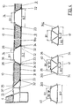
- Figure 1 shows a half cross section of a typical car body structure.
- the vertical axis is designated 6. It forms the axis of symmetry for the cross section.
- the longitudinal axis 7 is also shown. This is the axis that extends into the plane of the drawing sheet and is intended to represent the length of the body structure and its direction of travel.
- the car body structure shown in cross section comprises the floor 1, which is fastened to the long beam 4.
- the long beam 4 extends parallel to the longitudinal axis 7. It represents the link between the floor 1 and the side wall 2.
- an upper flange 5 which also extends parallel to the longitudinal axis 7 and serves as a link to the roof 3.
- An opening for a window 8 is shown in the side wall 2.
- FIG. 2 shows a first variant for the base 1.
- the base 1 is constructed from a base profile 9, a cover plate 10 attached to it and an insulation 11 located between the two and an edge profile 13 and a central profile 14.
- an anti-drumming coating 12 is provided.
- the basic profile 9 consists of a plate 18 which is provided with webs 17 projecting from its surface 19.
- the webs 17 are spaced apart and run parallel to the longitudinal axis 7. They have flanges 20 at their ends, which form flange surfaces 21.
- the webs 17 and flanges 20 are designed in one piece with the plate 18 and, together with this, are produced as an extruded profile from an aluminum material.
- the longitudinal edge 22 of the plate 18 of the base profile 9 is welded to the edge profile 13.
- the edge profile 13 is designed as an aluminum hollow profile and has a triangular cross section.
- Two walls 27, 28 are essentially perpendicular to one another.
- the wall 29 connects the two walls 27, 28.
- a contact surface 35 is provided on a projection.
- the contact surface 35 serves to support the plate 18 in the region of its longitudinal edge 22 and has one Groove on, so that a weld pool support for attaching the fusion weld 32 is formed.
- Flanges 30, 31 of different lengths protrude at right angles from the wall 28 of the edge profile 13 and serve to rest on corresponding flanges 15, 16 of the long beam 4 and are firmly connected to the latter by means of weld seams 32.
- the other longitudinal edge 23 of the plate 18 of the basic profile 9 is welded to the central profile 14.
- the center profile 14 also has a recess with a contact surface 34 which is designed as a weld pool support. Center profile 14 and plate 18 are firmly connected to one another by the weld seam 32.
- the flange surfaces 21 of the webs 17 associated with the flanges 20 form support surfaces for the cover plate 10.
- the ends of the cover plate 10 are placed on support surfaces 25 of the edge profile 13 and 26 of the center profile 14.
- the cover plate 10 is fixedly connected to the flange surface 21 of the base profile 9 or the contact surfaces 25, 26 of the edge profile 13 and the center profile 14 by means of an adhesive or another joining method (riveting, screwing, welding).
- the inner surface 24 of the cover plate 10 and the surface 19 of the plate 18 as well as the surface of the wall 29 of the edge profile 13 pointing towards the cavity or the corresponding surface of the center profile 14 are provided with an anti-drumming coating 12.
- Insulation 11 is also provided in the remaining cavity. Such insulation 11 can be made of glass or rock wool, for example, and is used for thermal or acoustic insulation.
- FIG. 3 shows an alternative design of a section of the basic profile 9a.
- some of the crosspieces 17a are inclined at an angle W.
- Their flanges 20a and flange surfaces 21a are also used for connection to the cover plate 10, for example. B. by gluing.
- Such an arrangement better absorbs thrust forces which act on the box formed.
- the vertical loads, which occur particularly during the production of the bond, are absorbed directly by the webs 17 running at right angles to the plate 18.
- FIG. 4 shows a further design option for a floor structure.
- Several basic profiles 9 are provided, a central profile 14 being provided between two basic profiles 9.
- the center profiles 14 also have contact surfaces 34 which are designed to form weld pool supports.
- the basic profile 9, which is arranged adjacent to the left long beam 4, is connected to the edge profile 13 in the region of its contact surface 33 by the weld 32.
- the other longitudinal edge 23 is connected to the latter by a further weld seam 32 in the region of the contact surface 34 of the central profile 14.
- the further basic profile 9 is arranged between two central profiles 14. In the area of the surface assigned to the cover plate 10 of the central profiles 14, which are approximately trapezoidal in cross-section, support surfaces 26 are provided.
- a support surface 25 is shown in the area of the edge profile 13.
- the cover plate 10 is glued to these bearing surfaces 25, 26.
- the longitudinal edge 37 of the cover plate 10 is assigned to the edge profile 13 and the longitudinal edge 38 to the center profile 14.
- the central profile 14 In the intermediate area there is a configuration of the basic profile 9 corresponding to the configuration according to FIGS. 2 or 3 available.
- Various embodiments of the central profile 14 are shown below the illustration in FIG. 4, which shows the floor construction.
- the central profile 14a is provided with T-rails 40 pointing towards the interior of the body structure.
- the central profile 14a can also be produced as an extruded profile.
- the T-rails 40 can be used, for example, for attaching seats.
- a downward-pointing C-rail 41 is provided in addition to the upwardly pointing T-rails 40. This can be used, for example, to attach drive units outside the body structure.
- the middle profile 14c only an external C-rail 41 is provided.
- the center profiles can also be used in the area of the side walls in accordance with the design options described above. In order to ensure a simple exchange of the different construction variants of the center profiles 14, 14a, 14b and 14c, their construction widths B1 and B2 are chosen to be the same.
- the design of a particularly favorable cover plate 10 can be seen from FIG.
- the cover plate 10 consists of the two aluminum sheets 42, 43 arranged parallel to one another. These are held at a distance from one another via a corrugated sheet metal web 44 as the core.
- the metal sheets 42, 43, 44 are firmly connected to one another.
- a rigid structure is thus achieved.
- this structure also allows easy adaptation to an arcuate course if the bending axis extends parallel to the wave troughs 45.
- the arrangement is particularly in the Area of the bottom 1 taken so that the troughs 45 extend transversely to the longitudinal axis 7.
- a similar arrangement is provided in the area of the roof 3.
- FIG. 6 shows the structure of a side wall 2.
- the base profile 9b is selected in the area of the transition to the long beam 4. There is an increase in the free space between the plate 18b and the cover plate 10. In the region of a web 17b, an L-rail 55 is formed inwards on the inside. The channel 46 formed between one leg of the flange of the web 17b and the surface 19 of the plate 18 can be used for the arrangement of electrical lines 50.
- a chamber 47 is integrally formed, which after the production of the extruded profile in the form of the basic profile 9b can be opened in areas through openings 48 to the interior of the body structure. The chamber 47 can be used, for example, as an air duct.
- the basic profile 9b can also be designed such that a nose 51 protrudes inwards from the surface 19 from the plate 18b in the region of the windows to be fitted.
- This nose 51 can also be pressed on and facilitates the assembly of the window 8 in that a hollow chamber profile 52 is placed thereon, one section of which serves as an abutment for a first pane 53.
- the second disc 53 is arranged flush with the outer surface of the cover plate 10.
- a sealing profile 54 is located between the two. In the transition area between the two, a seal can be provided in the gap 59.
- the cover plate 10 over extends a portion of the profile of the long beam 4 and the same is glued to a support surface 39.
- a projection 57 is provided, to which the bearing surface 39 is set back.
- FIG. A profile 49 which is connected to the surface 19 of the plate 18 of the basic profile 9, is used to form the chamber 47.
- FIG. 8 shows a perspective view of a part of the body structure with the floor 1 and the base profile 9, 4 cross members 58 being additionally spaced apart from the long beams in order to additionally support the floor 1.
- the cover plate 10 can be seen, which is to be glued accordingly to the base profile 9 of the floor.
- the structure of the side wall 2 with the window openings 56 constructed from the basic profiles 9b can be seen. It can be seen that lines 50 can be guided, for example, both along the channels 46 formed and through openings through the webs 17. The breakthroughs can be achieved by working out the webs 17.
- the cover plate 10 After completion of the installation and installation of the insulation, the cover plate 10 can be glued on. Furthermore, the arrangement or connection between the side wall 2 and the roof 3 can be seen via the upper flange 5.
- the basic profile 9c is connected to the upper flange 5.
- the cover plate 10 can be placed on the base profile 9c after installation and insulation in the direction of the arrow and connected by gluing.
Landscapes
- Engineering & Computer Science (AREA)
- Life Sciences & Earth Sciences (AREA)
- Wood Science & Technology (AREA)
- Mechanical Engineering (AREA)
- Body Structure For Vehicles (AREA)
- Fittings On The Vehicle Exterior For Carrying Loads, And Devices For Holding Or Mounting Articles (AREA)
- Vehicle Interior And Exterior Ornaments, Soundproofing, And Insulation (AREA)
- Standing Axle, Rod, Or Tube Structures Coupled By Welding, Adhesion, Or Deposition (AREA)
- Platform Screen Doors And Railroad Systems (AREA)
Abstract
Description
Die Erfindung betrifft einen Wagenkastenaufbau, insbesondere für Eisenbahnwagen zur Personenbeförderung, mit einem Boden, zwei Seitenwänden, zwei Stirnwänden und einem Dach sowie Öffnungen in den Seitenwänden und/oder Stirnwänden in Form von Fenstern und/oder Türöffnungen, wobei der Boden mit den Seitenwänden durch Langträger und die Seitenwände mit dem Dach durch Obergurte verbunden sind und die Langträger und die Obergurte als Voll- oder Hohlprofile aus einem Aluminiumwerkstoff stranggepreßt sind und parallel zu einer Längsachse, die die Längenerstreckung des Wagenkastenaufbaus darstellt, verlaufen und wobei die Seitenwände Vollprofile mit Stegen aus einem Aluminiumwerkstoff, eine Isolierung und Deckplatten aufweisen.The invention relates to a body structure, in particular for railway carriages for passenger transport, with a floor, two side walls, two end walls and a roof and openings in the side walls and / or end walls in the form of windows and / or door openings, the floor with the side walls by long beams and the side walls are connected to the roof by upper straps and the long beams and the upper straps are extruded as solid or hollow profiles made of an aluminum material and run parallel to a longitudinal axis, which represents the longitudinal extension of the body structure, and wherein the side walls have solid profiles with webs made of an aluminum material , have insulation and cover plates.
Ein solcher Wagenkastenaufbau ist aus der EP 0 148 123 A2 bekannt. Nachteilig bei dieser Ausbildung ist, daß der Wandaufbau aus einer innenliegenden Tragstruktur und einer nichttragenden Außenhaut besteht. Hiermit ist ein erhöhter Platzbedarf gegenüber einer konventionellen Konstruktion verbunden. Der Innenraum der Fahrgastzelle verkleinert sich, da die äußeren Fahrzeugabmessungen gleich bleiben müssen. Zudem erhöht sich das Gewicht des Fahrzeuges, da zusätzlich zu der Tragstruktur eine zweite, nur dekorativen Zwecken dienende Struktur eingebaut ist.Such a body structure is known from EP 0 148 123 A2. A disadvantage of this design is that the wall structure consists of an internal supporting structure and a non-supporting outer skin. This is associated with an increased space requirement compared to a conventional construction. The interior of the passenger compartment is reduced in size since the outer vehicle dimensions must remain the same. In addition, the weight of the vehicle increases because, in addition to the supporting structure, a second structure is used, which is only used for decorative purposes.
Es ist auch üblich, einen Wagenkastenaufbau aus Blech und Aluminiumstrangpreßprofilen oder Stahlprofilen herzustellen, welche unter anderem auch die Außenkontur des Fahrzeuges bestimmen. Neben der heute üblichen Blech-Gerippe-Bauweise für Stahlfahrzeuge, die einen sehr hohen Richtaufwand zur Erzielung einer möglichst ebenen Außenfläche zur Folge hat, ist auch bei einer Aluminiumintegralbauweise die Oberflächenqualität nicht immer so gut, wie eigentlich gewünscht. Offene Strangpreßprofile werden dabei durch senkrecht zur Fahrzeuglängsrichtung verschweißte Profile versteift. Durch die Einbringung der Schweißwärme und unterschiedliche Abkühlverhältnisse können sich diese Versteifungsprofile an der Fahrzeugaußenhaut abzeichnen. Ohne Verwendung von Spachtelmaterial, auf das aus Kosten- und Gewichtsgründen jedoch in den meisten Fällen verzichtet werden soll, ist eine optisch einwandfreie Oberfläche nur schwer zu erzielen. Falls die Oberflächenqualität bei Verwendung von Hohlprofilen verbessert bzw. ausreichend sein sollte, müßten aber immer noch die Längsschweißnähte, die die Aluminiumstrangpreßprofile miteinander verbinden, abgearbeitet und verputzt werden. Dies bedeutet ebenfalls einen erhöhten Zeit- und Kostenaufwand. Bei leichten Kollisionen und bei anderen Beschädigungen wird die Tragstruktur, die im wesentlichen aus den Aluminium-Strangpreßprofilen oder Stahlprofilen besteht, und gleichzeitig auch Außenkontur des Fahrzeuges ist, unmittelbar beschädigt und bedarf einer sorgfältigen Reparatur. Diese Reparatur muß den optischen Ansprüchen wie vorbeschrieben gerecht werden.It is also common to produce a body structure from sheet metal and aluminum extrusions or steel profiles, which also determine the outer contour of the vehicle, among other things. In addition to the usual sheet metal frame structure for steel vehicles, which results in a very high level of straightening to achieve the most even outer surface possible, even with an integral aluminum construction, the surface quality is not always as good as actually desired. Open extruded profiles are stiffened by profiles welded perpendicular to the longitudinal direction of the vehicle. By introducing the welding heat and different cooling conditions, these stiffening profiles can be seen on the outer skin of the vehicle. Without the use of filler material, which should be avoided in most cases for reasons of cost and weight, it is difficult to achieve an optically perfect surface. If the surface quality should be improved or sufficient when using hollow profiles, the longitudinal weld seams that connect the aluminum extrusion profiles to each other would still have to be machined and plastered. This also means increased expenditure of time and money. In the event of slight collisions and other damage, the supporting structure, which essentially consists of the extruded aluminum or steel profiles and at the same time the outer contour of the vehicle, is immediately damaged and requires careful repair. This repair must meet the visual requirements as described above.
Der Erfindung liegt daher die Aufgabe zugrunde, einen Wagenkastenaufbau zu schaffen, der ein möglichst geringes Gewicht aufweist, bei dem der Zusammmenbau einfach gestaltet ist und darüber hinaus optisch einwandfreie Flächen im Sichtbereich erzielt werden können.The invention is therefore based on the object of providing a body structure which is as small as possible Has weight in which the assembly is simple and, moreover, optically perfect areas can be achieved in the field of vision.
Diese Aufgabe wird erfindungsgemäß dadurch gelöst, daß der Boden, die Seitenwände und das Dach jeweils aus mindestens einem Grundprofil aufgebaut sind, das als Aluminiumstrangpreßprofil gestaltet ist und aus einer Platte mit damit einstückigen, von einer Fläche der Platte vorstehenden Stegen mit Flanschen und Flanschflächen besteht, wobei die Stege parallel zur Längsachse verlaufen, daß die Stege zu den ebenfalls parallel zur Längsachse verlaufenden Längskanten der Platte mit Abstand angeordnet sind und parallel zu diesen verlaufen, daß die Längskanten der Platten unmittelbar oder mittelbar unter Zwischenschaltung von als Strangpreßprofil gestalteten Randprofilen an den Langträgern oder den Obergurten angeschweißt sind, daß die Deckplatten auf den Flanschflächen der Stege einerseits und den Auflageflächen der Langträger oder Randprofile andererseits aufliegen und mit diesen fest verbunden sind und somit zusammen die Tragstruktur in Form eines Hohlprofiles bilden, daß die Deckplatten im Bereich der Seitenwände und des Daches die Außenfläche im Bereich des Bodens die Innenfläche des Wagenkastenaufbaus bilden und daß im Zwischenraum zwischen Deckplatte und Platte Isoliermaterial angeordnet ist.This object is achieved in that the bottom, the side walls and the roof are each constructed from at least one basic profile which is designed as an extruded aluminum profile and consists of a plate with webs with flanges and flange surfaces projecting therefrom from one surface of the plate, wherein the webs run parallel to the longitudinal axis, that the webs are arranged at a distance from the longitudinal edges of the plate, which also run parallel to the longitudinal axis, and run parallel to these, that the longitudinal edges of the plates directly or indirectly with the interposition of edge profiles designed as extruded profiles on the long beams or the upper chords are welded on so that the cover plates rest on the flange surfaces of the webs on the one hand and the contact surfaces of the long beams or edge profiles on the other hand and are firmly connected to them and thus together form the supporting structure in the form of a hollow profile, that the cover plates in the area of the side walls and the roof form the outer surface in the area of the floor the inner surface of the body structure and that insulating material is arranged in the space between the cover plate and the plate.
Von Vorteil bei dieser Ausbildung ist, daß alle tragenden Grundprofile, Langträger, Obergurte und Randprofile aus Aluminiumstrangpreßprofilen hergestellt werden können, so daß alle Vorteile der Aluminium-Integralbauweise, z. B. Schweißbadstützen, Auflageflächen für Bleche und die Integration von Befestigungselementen genutzt werden können. Ein wesentlicher Vorteil besteht darin, daß auch die Deckplatte mit zur Aufnahme von Kräften herangezogen wird. Die Deckplatte trägt also zur Stabilität des gebildeten Hohlprofiles bei. Durch die nachträgliche Anbringung der Deckplatte wird ermöglicht, den Hohlraum für die Anordnung von Leitungen und auch Isoliermaterial zu nutzen. Es wird also ein günstiges Geräuschverhalten erzielt, ohne daß es des zusätzlichen Aufbringens von Dämmaterialien auf der Innenfläche des Wagenkastenaufbaus bedarf. Hierdurch wird die Größe des zur Verfügung stehenden Wageninnenraumes günstig beeinflußt. Zur Erzielung der festen Verbindung kommen verschiedene Fügeverfahren, z. B. Kleben, Schweißen, Nieten, Schrauben, in Frage.The advantage of this training is that all load-bearing basic profiles, long beams, top chords and edge profiles can be made from extruded aluminum profiles, so that all advantages of the integral aluminum construction, e.g. B. weld pool supports, contact surfaces for sheet metal and integration of fasteners can be used. A major advantage is that the cover plate is also used to absorb forces. The cover plate thus contributes to the stability of the hollow profile formed. The subsequent attachment of the cover plate makes it possible to use the cavity for the arrangement of lines and also insulating material. A favorable noise behavior is thus achieved without requiring the additional application of insulating materials on the inner surface of the body structure. As a result, the size of the available car interior is influenced favorably. Various joining methods are used to achieve the fixed connection, e.g. B. gluing, welding, riveting, screwing, in question.
In Ausgestaltung der Erfindung ist vorgesehen, daß das Dach, der Boden und/oder die Seitenwände aus mindestens zwei Grundprofilen bestehen, die jeweils über ein Mittenprofil verbunden sind, welches als Hohlkammerprofil gestaltet ist und aus einem Aluminiumwerkstoff stranggepreßt ist, wobei die Platten jeweils an einer Längskante mit dem Mittenprofil verschweißt sind.In an embodiment of the invention it is provided that the roof, the floor and / or the side walls consist of at least two basic profiles, each of which is connected via a central profile, which is designed as a hollow chamber profile and is extruded from an aluminum material, the plates each on one Long edge are welded to the central profile.
Von Vorteil hierbei ist, daß über das Mittenprofil eine zusätzliche Versteifung erreicht wird. Je nach Größe des Wagenkastenaufbaus können, zwecks Montage der meist unterflur angeordneten Geräte, vor allem im Boden ein oder mehrere Mittenprofile vorgesehen sein.The advantage here is that an additional stiffening is achieved via the central profile. Depending on the size of the car body structure, one or more center profiles can be provided, particularly in the floor, for the purpose of installing the mostly underfloor devices.
Vorzugsweise verlaufen die Stege vertikal zur Platte des Grundprofils und bilden mit den angeformten Flanschen im Querschnitt eine T-Form. Es ist jedoch auch eine Anordnung möglich, bei der einige der einer Platte zugeordneten Stege mit der Platte einen von 90° abweichenden Winkel bilden.The webs preferably run vertically to the plate of the basic profile and form a T-shape in cross section with the molded flanges. However, an arrangement is also possible in which some of those assigned to a plate Form bridges with the plate at an angle other than 90 °.
Hierdurch wird eine verbesserte Schubsteifigkeit der Gesamtplatte erreicht. Die senkrecht verlaufenden T-Stege sorgen für eine stabile Auflage für die Deckplatte.As a result, an improved shear rigidity of the entire plate is achieved. The vertical T-bars ensure a stable support for the cover plate.
Besonders für die Verwendung des Grundprofiles im Bereich der Seitenwände ist es zweckmäßig, parallel zur Längsachse verlaufende Kammern vorzusehen. Diese können beispielsweise als Luftführungskanäle für die Klimatisierung oder Heizung verwendet werden. In den Bereichen, in denen Austritte zum Innenraum des Wagenkastenaufbaus erforderlich sind, können entsprechende Durchbrüche eingefräst oder eingestanzt werden.Especially for the use of the basic profile in the area of the side walls, it is expedient to provide chambers running parallel to the longitudinal axis. These can be used, for example, as air ducts for air conditioning or heating. In the areas where exits to the interior of the body structure are required, appropriate openings can be milled or punched.
Dabei sind die Wände der Kammer bevorzugt einstückig mit dem Grundprofil gestaltet, d. h. sie können beim Strangpressen des Grundprofils mit hergestellt werden.The walls of the chamber are preferably designed in one piece with the basic profile, i. H. they can also be produced during extrusion of the basic profile.
Alternativ ist es jedoch auch möglich, die Kammer durch ein besonderes Profil zu bilden, welches an der Platte des Grundprofiles befestigt ist. Die Befestigung erfolgt an der Fläche der Platte, von der die Stege vorstehen.Alternatively, however, it is also possible to form the chamber by means of a special profile which is fastened to the plate of the basic profile. It is attached to the surface of the plate from which the webs protrude.
Die Randprofile sind in weiterer Ausgestaltung der Erfindung ebenfalls als Hohlprofile gestaltet und im Strangpreßverfahren hergestellt. Sie dienen zum Toleranzausgleich bei der Fertigung und besitzen im Querschnitt eine dreieckige Grundform mit zwei rechtwinklig aufeinanderstehenden Wänden. Von einer der beiden aufeinanderstehenden Wänden gehen von deren Ecken, die von dieser mit den anderen Wände gebildet werden, zueinander parallele Flansche aus. Diese verlaufen parallel zur Längsachse und dienen zur Verbindung mit entsprechenden Flanschen der Langträger oder Obergurte. Die Verbindung erfolgt durch Schmelzschweißnähte.In a further embodiment of the invention, the edge profiles are also designed as hollow profiles and are produced using the extrusion process. They are used to compensate for tolerances during production and have a triangular cross-section with two walls that are at right angles to one another. From one of the two walls standing on top of each other, the corners of this wall and that of the others Walls are formed from parallel flanges. These run parallel to the longitudinal axis and are used to connect the corresponding flanges of the long girders or top chords. The connection is made by fusion welds.
Zur Verbindung zwischen dem Langträger, den Obergurten, den Randprofilen oder den Mittenprofilen mit den Längskanten der Platten dienen vorzugsweise Rücksprünge, die Anlageflächen bilden. Die Anlageflächen sind so gestaltet, daß eine Schweißbadstütze entsteht. Hierzu ist im Übergang zwischen den beiden Flächen des Rücksprunges eine Rille zur Verbesserung der Schweißnahtqualität gestaltet. Für die Befestigung der Platten sind ebenfalls Auflageflächen an den Langträgern, den Obergurten, den Randprofilen oder den Mittenprofilen vorgesehen. Diese sind im Bereich von Rücksprüngen gegenüber den zugehörigen Außenflächen angeordnet. Der Spalt zwischen den Längskanten der Deckplatte und dem jeweiligen Rücksprung wird zur Abdichtung durch ein Versiegelungsmaterial ausgefüllt. In den Bereichen, die als Sichtflächen gestaltet sind, wird dadurch ein glatter Übergang vom Profil zur Deckplatte erreicht und somit das optische Erscheinungsbild verbessert.Recesses, which form contact surfaces, are preferably used to connect the long girder, the top chords, the edge profiles or the center profiles to the longitudinal edges of the plates. The contact surfaces are designed so that a weld pool support is created. For this purpose, a groove is designed in the transition between the two surfaces of the recess to improve the weld quality. Support surfaces are also provided on the long beams, the top chords, the edge profiles or the center profiles for fastening the panels. These are arranged in the area of recesses opposite the associated outer surfaces. The gap between the longitudinal edges of the cover plate and the respective recess is filled with a sealing material for sealing. In the areas that are designed as visible surfaces, a smooth transition from the profile to the cover plate is achieved, thus improving the visual appearance.
Der Hohlraum zwischen Grundprofil und Deckplatte und insbesondere der zwischen den Stegen, deren Flansche und der angrenzenden Fläche der Platte des Grundprofiles gebildete Kanal kann zur Aufnahme von Installationsleitungen, insbesondere Elektro- , Pneumatik- oder Hydraulikleitungen genutzt werden.The cavity between the base profile and cover plate and in particular the channel formed between the webs, their flanges and the adjacent surface of the plate of the base profile can be used to hold installation lines, in particular electrical, pneumatic or hydraulic lines.
Das Grundprofil, das Randprofil oder das Mittenprofil können, da sie als Strangpreßprofile gestaltet sind, zusätzlich mit angepreßten, im Querschnitt eine C- oder T-Schiene bildenden Ausformungen versehen sein, die sich parallel zu den Stegen erstrecken. Diese C- oder T-Schienen können dazu genutzt werden, beispielsweise Aggregate, sofern sie im Außenbereich des Wagenkastenaufbaus liegen, an dem Wagenkasten zu befestigen oder sie können auch bei Anbringung zum Innern des Wagenkastenaufbaues hin, für die Anbringung von Sitzen, Innenraumverkleidungen, Lampenbändern, etc. dienen.The basic profile, the edge profile or the central profile can also, since they are designed as extruded profiles be provided with pressed-in, cross-sectionally forming a C or T rail, which extend parallel to the webs. These C- or T-rails can be used, for example, to attach units, provided they are in the outer area of the body structure, to the body or they can also be attached to the interior of the body structure, for attaching seats, interior panels, lamp strips, etc. serve.
Die Anordnung der Grundprofile soll vorzugsweise so gewählt werden, daß bei einer Seitenwand, die aus zwei Grundprofilen gebildet ist und mit Fensterdurchbrüchen versehen ist, die Schweißverbindung zweier Grundprofile auf halber Höhe der Fensterdurchbrüche angeordnet ist.The arrangement of the basic profiles should preferably be chosen so that in the case of a side wall which is formed from two basic profiles and is provided with window openings, the welded connection of two basic profiles is arranged halfway up the window openings.
Im Bereich der Seitenwände sind die Grundprofile vorzugsweise unmittelbar an den Langträgern und den Obergurten verschweißt. Auf Randprofile kann verzichtet werden, da ein Höhenausgleich nicht erforderlich ist.In the area of the side walls, the basic profiles are preferably welded directly to the long beams and the top chords. There is no need for edge profiles because height adjustment is not necessary.
Vorzugsweise sind im Berich des Daches zusätzliche Randprofile vorgesehen, welche dazu dienen, das Dach mit den beiden Obergurten zu verschweißen und hierbei analog zum Boden die Breitentoleranz des Wagenkastens einzuhalten.Additional edge profiles are preferably provided in the area of the roof, which are used to weld the roof to the two upper chords and to maintain the width tolerance of the car body analogous to the floor.
Besonders günstige Festigkeitseigenschaften ergeben sich, wenn die Deckplatte als Verbundplatte aufgebaut ist. Sie besteht in diesem Fall aus zwei Blechen oder Kunststoffplatten zwischen denen ein Kern ausgebildet ist.Particularly favorable strength properties result if the cover plate is constructed as a composite plate. In this case it consists of two sheets or plastic plates between which a core is formed.
Eine besonders günstige Konstruktion für die Deckplatte ergibt sich, wenn die Deckplatte aus zwei parallelen Aluminiumblechen und einer dazwischen angeordneten gewellten Blechbahn als Kern gebildet ist. Diese Bleche sind unlösbar miteinander verbunden.A particularly favorable construction for the cover plate results if the cover plate consists of two parallel aluminum sheets and an intermediate corrugated sheet metal sheet is formed as a core. These sheets are inextricably linked.
Alternativ ist es möglich, die Deckplatte aus zwei parallelen Kunststoffplatten mit dazwischen angeordneten Schaumkern auszubilden.Alternatively, it is possible to form the cover plate from two parallel plastic plates with a foam core arranged between them.
Die Kunststoffplatten können als faserverstärkte Kunststoffplatten gestaltet sein.The plastic plates can be designed as fiber-reinforced plastic plates.
Eine besonders gute Steifigkeit der gesamte Tragstruktur ergibt sich, wenn die Deckplatten im Bereich des Bodens und Daches in Fahrzeugquerrichtung, d. h. quer zur Längsachse, und in den Seitenwänden ebenfalls quer zur Längsachse, jedoch senkrecht von oben nach unten verlaufend, angeordnet sind.A particularly good rigidity of the entire support structure is obtained if the cover plates in the area of the floor and roof in the transverse direction of the vehicle, i. H. transversely to the longitudinal axis, and in the side walls also transversely to the longitudinal axis, but extending vertically from top to bottom.
Um die Montage der Fensterprofile zu erleichtern, ist in der Ausgestaltung vorgesehen, das Grundprofil mit einer senkrecht zur Grundfläche verlaufenden Nase als Anschlag für das Fensterprofil zu gestalten.In order to facilitate the assembly of the window profiles, the design provides for the base profile to be designed with a nose running perpendicular to the base area as a stop for the window profile.
Besonders günstige Geräuschdämmeigenschaften ergeben sich, wenn entsprechend einer weiteren Ausgestaltung die Fläche der Platte des Grundprofils, aus der die Stege vorstehen und/oder die dieser gegenüberliegende Fläche der Deckplatte mit einer Antidröhnmasse, wie beispielsweise Spritzkork oder spritzbare Mineralfasern, beschichtet sind.Particularly favorable noise insulation properties result if, according to a further embodiment, the surface of the plate of the basic profile from which the webs protrude and / or the surface of the cover plate opposite this are coated with an anti-drumming compound, such as, for example, spray cork or sprayable mineral fibers.
Bevorzugte Ausführungsbeispiele der Erfindung sind in der Zeichnung schematisch dargestellt.Preferred embodiments of the invention are shown schematically in the drawing.
Es zeigt
Figur 1- einen typischen Wagenkastenquerschnitt mit dem erfindungsgemäßen Aufbau,
Figur 2- ein erstes Ausführungsbeispiel eines Bodens des Wagenkastenaufbaus,
Figur 3- eine alternative Gestaltung des Aufbaus des Bodens,
Figur 4- eine weitere Ausführungsform für die Gestaltung des Bodens,
Figur 5- einen Aufbau einer Deckplatte,
Figur 6- eine Ausführungsform des Aufbaus einer Seitenwand,
- Figur 7
- eine alternative Gestaltung eines Details des Seitenwandaufbaus und
Figur 8- ausschnittsweise eine perspektivische Ansicht der Wagenkastenkonstruktion.
- Figure 1
- a typical car body cross section with the structure according to the invention,
- Figure 2
- a first embodiment of a floor of the body structure,
- Figure 3
- an alternative design of the structure of the floor,
- Figure 4
- another embodiment for the design of the floor,
- Figure 5
- a structure of a cover plate,
- Figure 6
- one embodiment of the construction of a side wall,
- Figure 7
- an alternative design of a detail of the side wall structure and
- Figure 8
- a partial perspective view of the car body construction.
Figur 1 zeigt einen halben Querschnitt eines typischen Wagenkastenaufbaus. Die Hochachse ist mit 6 bezeichnet. Sie bildet die Symmetrieachse für den Querschnitt.Figure 1 shows a half cross section of a typical car body structure. The vertical axis is designated 6. It forms the axis of symmetry for the cross section.
Darüber hinaus ist die Längsachse 7 eingezeichnet. Dies ist die Achse, die sich in die Zeichenblattebene hinein erstreckt und die Längenerstreckung des Wagenkastenaufbaus sowie dessen Fahrtrichtung repräsentieren soll.The longitudinal axis 7 is also shown. This is the axis that extends into the plane of the drawing sheet and is intended to represent the length of the body structure and its direction of travel.
Der im Querschnitt ersichtliche Wagenkastenaufbau umfaßt den Boden 1, der an dem Langträger 4 befestigt ist. Der Langträger 4 erstreckt sich parallel zur Längsachse 7. Er stellt das Bindeglied zwischen Boden 1 und Seitenwand 2 dar. Im oberen Bereich der Seitenwand 2 ist ein Obergurt 5 angebracht, welcher sich ebenfalls parallel zur Längsachse 7 erstreckt und als Bindeglied zum Dach 3 dient. In der Seitenwand 2 ist ein Durchbruch für ein Fenster 8 dargestellt.The car body structure shown in cross section comprises the
Figur 2 zeigt eine erste Variante für den Boden 1. Der Boden 1 ist aus einem Grundprofil 9, einer daran angebrachten Deckplatte 10 und einer zwischen beiden befindlichen Isolierung 11 und einem Randprofil 13 und einem Mittenprofil 14 aufgebaut. Zusätzlich ist eine Antidröhnbeschichtung 12 vorgesehen. Das Grundprofil 9 besteht aus einer Platte 18, die mit von ihrer Fläche 19 vorstehenden Stegen 17 versehen ist. Die Stege 17 sind zueinander beabstandet und verlaufen parallel zur Längsachse 7. Sie weisen an ihren Enden Flansche 20 auf, die Flanschflächen 21 bilden. Die Stege 17 und Flansche 20 sind einstückig mit der Platte 18 ausgestaltet und zusammen mit dieser als Strangpreßprofil aus einem Aluminiumwerkstoff hergestellt.FIG. 2 shows a first variant for the
Die Längskante 22 der Platte 18 des Grundprofils 9 ist mit dem Randprofil 13 verschweißt. Das Randprofil 13 ist als Aluminiumhohlprofil gestaltet und im Querschnitt dreieckförmig aufgebaut. Zwei Wände 27,28 stehen im wesentlichen senkrecht aufeinander. Die Wand 29 verbindet die beiden Wände 27,28. Im Bereich der Ecke zwischen den beiden Wänden 27 und 29 ist eine Anlagefläche 35 an einem Vorsprung vorgesehen. Die Anlagefläche 35 dient zur Auflage der Platte 18 im Bereich ihrer Längskante 22 und weist eine Rille auf, so daß eine Schweißbadstütze zur Anbringung der Schmelzschweißnaht 32 gebildet ist. Von der Wand 28 des Randprofils 13 stehen rechtwinklig Flansche 30,31 unterschiedlicher Länge vor, die zur Auflage an entsprechenden Flanschen 15,16 des Langträgers 4 dienen und mit diesem über Schweißnähte 32 fest verbunden sind. Die andere Längskante 23 der Platte 18 des Grundprofils 9 ist mit dem Mittenprofil 14 verschweißt. Hierzu weist das Mittenprofil 14 ebenfalls einen Rücksprung mit einer Anlagefläche 34 auf, die als Schweißbadstütze gestaltet ist. Mittenprofil 14 und Platte 18 sind durch die Schweißnaht 32 miteinander fest verbunden.The
Die den Flanschen 20 zugehörigen Flanschflächen 21 der Stege 17 bilden Auflageflächen für die Deckplatte 10. Die Enden der Deckplatte 10 sind auf Auflageflächen 25 des Randprofils 13 bzw. 26 des Mittenprofils 14 aufgelegt. Die Deckplatte 10 ist mit der Flanschfläche 21 des Grundprofils 9 bzw. den Auflageflächen 25,26 von Randprofil 13 und Mittenprofil 14 durch eine Klebung oder ein sonstiges Fügeverfahren (Nieten, Schrauben, Schweißen) fest verbunden. Die Innenfläche 24 der Deckplatte 10 und die Fläche 19 der Platte 18 sowie die zu dem Hohlraum hinweisende Fläche der Wand 29 des Randprofiles 13 bzw. die entsprechende Fläche des Mittenprofiles 14 sind mit einer Antidröhnbeschichtung 12 versehen. Ferner ist in dem verbleibenden Hohlraum eine Isolierung 11 angebracht. Eine solche Isolierung 11 kann beispielsweise aus Glas- oder Steinwolle bestehen und dient zur thermischen bzw. akustischen Isolierung.The flange surfaces 21 of the
Figur 3 zeigt eine alternative Gestaltung eines Ausschnittes des Grundprofiles 9a. In Abwandlung zur Gestaltung der Stege 17 gemäß Figur 3 verlaufen einige der Stege 17a geneigt unter dem Winkel W. Deren Flansche 20a und Flanschflächen 21a dienen ebenfalls zur Verbindung mit der Deckplatte 10 z. B. durch Klebung. Durch eine solche Anordnung werden Schubkräfte, die auf den gebildeten Kasten einwirken, besser aufgenommen. Die Vertikallasten, die vor allem bei der Herstellung der Verklebung auftreten, werden unmittelbar durch die rechtwinklig zur Platte 18 verlaufenden Stege 17 aufgenommen.FIG. 3 shows an alternative design of a section of the
Figur 4 zeigt eine weitere Ausgestaltungsmöglichkeit für einen Bodenaufbau. Dabei sind jeweils mehrere Grundprofile 9 vorgesehen, wobei jeweils zwischen zwei Grundprofilen 9 ein Mittenprofil 14 vorhanden ist. Die Mittenprofile 14 weisen ebenfalls Anlageflächen 34 auf, die zur Bildung von Schweißbadstützen ausgestaltet sind. Das Grundprofil 9, das benachbart zu dem linken Langträger 4 angeordnet ist, ist mit dem Randprofil 13 im Bereich dessen Anlagefläche 33 durch die Schweißnaht 32 verbunden. Die andere Längskante 23 ist durch eine weitere Schweißnaht 32 im Bereich der Anlagefläche 34 des Mittenprofils 14 mit diesem verbunden. In ähnlicher Weise ist das weitere Grundprofil 9 zwischen zwei Mittenprofilen 14 angeordnet. Im Bereichder der Deckplatte 10 zugeordneten Fläche der im Querschnitt in etwa Trapezform aufweisenden Mittenprofile 14 sind Auflageflächen 26 vorgesehen. Im Bereich des Randprofiles 13 ist eine Auflagefläche 25 dargestellt. Die Deckplatte 10 ist auf diesen Auflageflächen 25,26 aufgeklebt. Dabei ist die Längskante 37 der Deckplatte 10 dem Randprofil 13 und die Längskante 38 dem Mittenprofil 14 zugeordnet. Im Zwischenbereich ist eine Ausgestaltung des Grundprofiles 9 entsprechend der Ausgestaltung gemäß der Figuren 2 oder 3 vorhanden. Unterhalb der Darstellung von Figur 4, die die Bodenkonstruktion zeigt, sind verschiedene Ausführungsformen des Mittenprofiles 14 dargestellt. Das Mittenprofil 14a ist mit zum Innenraum des Wagenkastenaufbaus weisenden T-Schienen 40 versehen. Das Mittenprofil 14a kann ebenfalls als Strangpreßprofil hergestellt werden. Die T-Schienen 40 können beispielsweise zur Anbringung von Sitzen genutzt werden.FIG. 4 shows a further design option for a floor structure. Several
Bei der Ausgestaltung des Mittenprofiles 14b ist neben den nach oben weisenden T-Schienen 40 eine nach unten weisenden C-Schiene 41 vorgesehen. Diese kann beispielsweise zur Anbringung von Antriebsaggregaten außerhalb des Wagenkastenaufbaus genutzt werden. Bei dem Mittenprofil 14c ist lediglich eine außen liegende C-Schiene 41 vorgesehen. Eine Anwendung der Mittenprofile entsprechend der vorbeschriebenen Gestaltungsmöglichkeiten kann auch im Bereich der Seitenwände vorhanden sein. Um einen einfachen Austausch der unterschiedlichen Konstruktionvarianten der Mittenprofile 14,14a,14b und 14c zu gewährleisten, sind deren Konstruktionsbreiten B1 und B2 gleich gewählt.In the configuration of the
Aus Figur 5 ist die Gestaltung einer besonders günstigen Deckplatte 10 zu ersehen. Die Deckplatte 10 besteht aus den beiden parallel zueinander angeordneten Aluminiumblechen 42,43. Diese werden über eine gewellte Blechbahn 44 als Kern auf Abstand zueinander gehalten. Die Blechbahnen 42,43,44 sind fest miteinander verbunden. Es wird somit eine steife Struktur erzielt. Diese Struktur erlaubt jedoch auch ein einfaches Anpassen an einen bogenförmigen Verlauf, wenn die Biegeachse sich parallel zu den Wellentälern 45 erstreckt. Die Anordnung ist insbesondere im Bereich des Bodens 1 so getroffen, daß die Wellentäler 45 sich quer zur Längsachse 7 erstrecken. Eine gleiche Anordnung ist im Bereich des Daches 3 vorgesehen.The design of a particularly
Figur 6 zeigt den Aufbau einer Seitenwand 2.FIG. 6 shows the structure of a
Es ist ersichtlich, daß im Bereich des Überganges zum Langträger 4 eine andere Konstruktion des Grundprofiles 9b gewählt ist. Es erfolgt eine Vergrößerung des Freiraumes zwischen der Platte 18b und der Deckplatte 10. Im Bereich eines Steges 17b ist nach innen vorstehend eine L-Schiene 55 angeformt. Der zwischen einem Schenkel des Flansches des Steges 17b und der Fläche 19 der Platte 18 gebildete Kanal 46 kann zur Anordnung von Elektroleitungen 50 ge-nutzt werden. Es ist eine Kammer 47 angeformt, die nach der Herstellung des Strangpreßprofiles in Form des Grundprofiles 9b bereichsweise durch Durchbrüche 48 zum inneren des Wagenkastenaufbaus geöffnet werden kann. Die Kammer 47 kann beispielsweise als Luftführungskanal genutzt werden.It can be seen that a different construction of the
Ferner kann das Grundprofil 9b auch so gestaltet sein, daß von der Platte 18b im Bereich der anzubringenden Fenster eine Nase 51 nach innen von der Fläche 19 vorsteht. Diese Nase 51 kann mit angepreßt werden und erleichtert die Montage des Fensters 8 insofern, als ein Hohlkammerprofil 52 hieran angelegt wird, dessen einer Abschnitt als Anlage für eine erste Scheibe 53 dient. Die zweite Scheibe 53 ist bündig mit der Außenfläche der Deckplatte 10 verlaufend angeordnet. Zwischen beiden befindet sich ein Dichtungsprofil 54. Im Übergangsbereich zwischen beiden kann im Spalt 59 eine Versiegelung vorgesehen sein. Aus Figur 6 ist ebenfalls erkennbar, daß die Deckplatte 10 sich über einen Teilbereich des Profiles des Langträgers 4 erstreckt und an einer Auflagefläche 39 desselben verklebt ist. Im unteren Bereich des Langträgers 4 ist ein Vorsprung 57 vorgesehen, zu dem die Auflagefläche 39 zurückversetzt ist. Zwischen der Längskante der Deckplatte 10 und dem Vorsprung 57 ist ein Spalt 59 vorhanden, der durch eine Versiegelungsmasse abgedichtet ist.Furthermore, the
Aus Figur 7 ist eine alternative Gestaltung hinsichtlich der Anbringung der Kammer 47 zur Luftführung ersichtlich. Zur Bildung der Kammer 47 dient ein Profil 49, das mit der Fläche 19 der Platte 18 des Grundprofiles 9 verbunden ist.An alternative design with regard to the attachment of the
Figur 8 zeigt in perspektivischer Darstellung einen Teil des Wagenkastenaufbaus mit dem Boden 1 und dem Grundprofil 9, wobei zusätzlich noch den Langträgern 4 Querträger 58 beabstandet zugeordnet sind, um den Boden 1 zusätzlich zu stützen. Es ist die Deckplatte 10 erkennbar, die entsprechend auf dem Grundprofil 9 des Bodens zu verkleben ist. Ferner ist die aus den Grundprofilen 9b aufgebaute Struktur der Seitenwand 2 mit den Fensterdurchbrüchen 56 ersichtlich. Es ist erkennbar, daß Leitungen 50, beispielsweise sowohl entlang der gebildeten Kanäle 46 als auch durch Durchbrüche quer zu den Stegen 17 geführt werden können. Die Durchbrüche können durch Herausarbeiten der Stege 17 erzielt werden.FIG. 8 shows a perspective view of a part of the body structure with the
Nach Fertigstellung der Installation und Anbringung der Isolierung kann die Deckplatte 10 aufgeklebt werden. Ferner ist die Anordnung bzw. Verbindung zwischen Seitenwand 2 und Dach 3 über den Obergurt 5 erkennbar. Das Grundprofil 9c ist mit dem Obergurt 5 verbunden. Die Deckplatte 10 kann nach Fertigstellung vor Installationen und der Isolierung in Pfeilrichtung auf das Grundprofil 9c aufgelegt und durch Klebung verbunden werden.After completion of the installation and installation of the insulation, the
- 11
- Bodenground
- 22nd
- SeitenwandSide wall
- 33rd
- Dachtop, roof
- 44th
- LangträgerLong girder
- 55
- ObergurtTop chord
- 66
- HochachseVertical axis
- 77
- LängsachseLongitudinal axis
- 88th
- Fensterwindow
- 9,9a,9b,9c9.9a, 9b, 9c
- GrundprofilBasic profile
- 1010th
- DeckplatteCover plate
- 1111
- Isolierunginsulation
- 1212th
- AntidröhnbeschichtungAnti-drone coating
- 1313
- RandprofilEdge profile
- 14,14a,14b,14c14, 14a, 14b, 14c
- MittenprofilCenter profile
- 15,1615.16
- Flansch des LangträgersLong girder flange
- 17,17a,17b17.17a, 17b
- Stegweb
- 18,18a,18b18, 18a, 18b
- Platteplate
- 1919th
- Flächearea
- 20,20a20.20a
- Flanschflange
- 21,21a21.21a
- FlanschflächeFlange surface
- 22,2322.23
- LängskantenLong edges
- 2424th
- Innenfläche der DeckplatteInner surface of the cover plate
- 2525th
- Auflagefläche RandprofilContact surface edge profile
- 2626
- Auflagefläche MittenprofilContact surface center profile
- 27,28,2927,28,29
- Wändewalls
- 30,3130.31
- Flanschflange
- 3232
- SchweißnahtWeld
- 33,34,35,3633,34,35,36
- AnlageflächeContact surface
- 37,3837.38
- LängskanteLong edge
- 3939
- AuflageflächeContact surface
- 4040
- T-SchienenT-rails
- 4141
- C-SchieneC-rail
- 42,4342.43
- BlecheSheets
- 4444
- Kern/gewellte BahnCore / corrugated sheet
- 4545
- WellentalWave trough
- 4646
- Kanalchannel
- 4747
- Kammerchamber
- 4848
- Durchbruchbreakthrough
- 4949
- Profilprofile
- 5050
- ElektroleitungElectrical wiring
- 5151
- Nasenose
- 5252
- HohlkammerprofilHollow chamber profile
- 5353
- Scheibedisc
- 5454
- DichtungsprofilSealing profile
- 5555
- L-SchieneL-rail
- 5656
- FensterdurchbruchWindow breakthrough
- 5757
- Vorsprunghead Start
- 5858
- QuerträgerCross member
- 5959
- Spaltgap
- WW
- Winkelangle
- B1,B2B1, B2
- Breitewidth
Claims (23)
dadurch gekennzeichnet,
daß der Boden (1), die Seitenwände (2) und das Dach (3) jeweils aus mindestens einem Grundprofil (9,9a-c) aufgebaut sind, das als Aluminiumstrangpreßprofil gestaltet ist und aus einer Platte (18,18a,18b) mit damit einstückigen, von einer Fläche (19) der Platte (18,18a,18b) vorstehenden Stegen (17,17a,17b) mit Flanschen (20) und Flanschflächen (21,21a) besteht, wobei die Stege (17,17a,17b) parallel zur Längsachse (7) verlaufen, daß die Stege (17,17a,17b) zu den ebenfalls parallel zur Längsachse (7) verlaufenden Längskanten (22,23) der Platte (18) mit Abstand angeordnet sind und parallel zu diesen verlaufen, daß die Längskanten (22,23) der Platten (18,18a,18b) unmittelbar oder mittelbar unter Zwischenschaltung von als Strangpreßprofil gestalteten Randprofilen (13) an den Langträgern (4) oder den Obergurten (5) angeschweißt sind, daß die Deckplatten (10) auf den Flanschflächen (21,21a) der Stege (17,17a,17b) der Grundprofile (9,9a-c) einerseits und den Auflageflächen (25,26,37) der Langträger (4) oder Randprofile (13) andererseits aufliegen und mit diesen fest verbunden sind und somit zusammen die Tragstruktur in Form eines Hohlprofils bilden, daß die Deckplatten (10) im Bereich der Seitenwände (2) und des Daches (3) die Außenfläche und im Bereich des Bodens (1) die Innenfläche des Wagenkastenaufbaus bilden und daß im Zwischenraum jeweils zwischen Deckplatte (10) und Platte (18) Isoliermaterial (Isolierung 11) angeordnet ist.Body structure, in particular for railway carriages for passenger transport, with a floor (1), two side walls (2), two end walls and a roof (3) as well as openings in the side walls (2) and / or end walls in the form of windows (8) and / or door openings, the floor (1) being connected to the side walls (2) by long beams (4) and the side walls (2) to the roof (3) by upper straps (5) and the long beams (4) and upper straps (5 ) are extruded as solid or hollow profiles made of an aluminum material and run parallel to a longitudinal axis (7), which represents the longitudinal extent of the body structure, and the side walls (2) solid profiles with webs (17, 17a, 17b) made of an aluminum material, one Have insulation (11) and cover plates (10),
characterized,
that the bottom (1), the side walls (2) and the roof (3) are each constructed from at least one base profile (9.9a-c), which is designed as an extruded aluminum profile and from a plate (18, 18a, 18b) thus integral with webs (17, 17a, 17b) projecting from a surface (19) of the plate (18, 18a, 18b) There are flanges (20) and flange surfaces (21, 21a), the webs (17, 17a, 17b) running parallel to the longitudinal axis (7), that the webs (17, 17a, 17b) are also parallel to the longitudinal axis (7) extending longitudinal edges (22, 23) of the plate (18) are arranged at a distance and parallel to them, that the longitudinal edges (22, 23) of the plates (18, 18a, 18b) directly or indirectly with the interposition of edge profiles designed as extruded profiles ( 13) are welded to the long girders (4) or the upper chords (5) that the cover plates (10) on the flange surfaces (21, 21a) of the webs (17, 17a, 17b) of the basic profiles (9, 9a-c) on the one hand and rest on the support surfaces (25, 26, 37) of the long beams (4) or edge profiles (13) and are firmly connected to them and thus together form the support structure in the form of a hollow profile such that the cover plates (10) in the region of the side walls ( 2) and the roof (3) the outer surface and in the area of the floor (1) the inner surface che form the body structure and that in the space between the cover plate (10) and plate (18) insulating material (insulation 11) is arranged.
dadurch gekennzeichnet,
daß das Dach (3), der Boden (1) und/oder die Seitenwände (2) aus mindestens zwei Grundprofilen (9) besteht, die jeweils über ein Mittenprofil (14,14a-c) verbunden sind, welches als Hohlkammerprofil gestaltet ist und aus einem Aluminiumwerkstoff stranggepreßt ist, wobei die Platten (18,18a,18b) jeweils an einer Längskante (23) mit dem Mittenprofil (14,14a-c) verschweißt sind.Body structure according to claim 1,
characterized,
that the roof (3), the bottom (1) and / or the side walls (2) consists of at least two basic profiles (9), each of which is connected via a central profile (14, 14a-c), which is designed as a hollow chamber profile and is extruded from an aluminum material, wherein the plates (18, 18a, 18b) are each welded to the central profile (14, 14a-c) on one longitudinal edge (23).
dadurch gekennzeichnet,
daß mindestens einer der Stege (17) vertikal zur Platte (18,18a,18b) des Grundprofils (9,9a-c) verläuft.Body structure according to one of claims 1 or 2,
characterized,
that at least one of the webs (17) runs vertically to the plate (18, 18a, 18b) of the basic profile (9.9a-c).
dadurch gekennzeichnet,
daß einige der einer Platte (18) des Grundprofils (9a) zugeordneten Stege (17a) einen von 90° abweichenden Winkel (W) mit der Platte (18) bilden.Body structure according to one of claims 1 or 2,
characterized,
that some of the webs (17a) assigned to a plate (18) of the basic profile (9a) form an angle (W) deviating from 90 ° with the plate (18).
dadurch gekennzeichnet,
daß das Grundprofil (9b) zusätzlich mindestens eine, parallel zur Längsachse (7) verlaufende Kammer aufweist.Body structure according to claim 1,
characterized,
that the basic profile (9b) additionally has at least one chamber running parallel to the longitudinal axis (7).
dadurch gekennzeichnet,
daß die Wände der Kammer (47) einstückig mit dem Grundprofil (9b) stranggepreßt sind.Body structure according to claim 5,
characterized,
that the walls of the chamber (47) are extruded in one piece with the base profile (9b).
dadurch gekennzeichnet,
daß die Kammer (47) durch die Platte (18b) des Grundprofils (9b) und durch ein an der Fläche (19) der Platte (18b), von der die Stege (17b) vorstehen, befestigtes Profil (49) gebildet ist.Body structure according to claim 5,
characterized,
that the chamber (47) is formed by the plate (18b) of the base profile (9b) and by a profile (49) fastened to the surface (19) of the plate (18b) from which the webs (17b) protrude.
dadurch gekennzeichnet,
daß die Stege (17,17a,17b) mit den angeformten Flanschen (20) im Querschnitt eine T-Form bilden.Body structure according to one of claims 1 to 7,
characterized,
that the webs (17, 17a, 17b) with the molded flanges (20) form a T-shape in cross section.
dadurch gekennzeichnet,
daß die Randprofile (13) als Hohlprofil, mit im Querschnitt dreieckiger Grundform mit zwei rechtwinklig aufeinanderstehenden Wänden (27,28) gebildet sind, wobei von einer der beiden vorgenannten Wände (28) mit der anderen Wand (29) gebildeten Ecken ausgehend zueinander parallele Flansche (30,31) vorstehen, die parallel zur Längsachse (7) verlaufen und zur Verbindung mit entsprechenden Flanschen (15,16) der Langträger (4) oder Obergurte (5) durch Schweißen (Schweißnaht 32) dienen.Body structure according to claim 1,
characterized,
that the edge profiles (13) are formed as a hollow profile with a triangular basic cross-section with two mutually perpendicular walls (27, 28), with flanges parallel to each other starting from one of the two aforementioned walls (28) with the other wall (29) (30, 31) project, which run parallel to the longitudinal axis (7) and are used for connection to corresponding flanges (15, 16) of the long girders (4) or top chords (5) by welding (weld seam 32).
dadurch gekennzeichnet,
daß die Langträger (4), die Obergurte (5), die Randprofile (13) oder die Mittenprofile (14,14a-c) jeweils mit einer von ihrer Außenfläche zurückversetzten Anlagefläche (33-36) zur Bildung einer Schweißbadstütze versehen sind und diese mit den Längskanten (22,23) der Platte (18,18a,18b) durch eine durchgehende Schmelzschweißnaht (32) verbunden sind.Body structure according to one of claims 1 to 9,
characterized,
that the long girders (4), the top chords (5), the edge profiles (13) or the central profiles (14, 14a-c) are each provided with a contact surface (33-36) set back from their outer surface to form a weld pool support and this with the longitudinal edges (22, 23) of the plate (18, 18a, 18b ) are connected by a continuous fusion weld seam (32).
dadurch gekennzeichnet,
daß Auflageflächen (25,26,39) für die Deckplatten (10) an den Langträgern (4), den Obergurten (5), den Randprofilen (13) oder Mittenprofilen (14,14a-c) einem Rücksprung gegenüber der zugehörigen Außenfläche zugeordnet sind und der Spalt (59) zwischen den Längskanten (37,38) der Deckplatte (10) und dem Rücksprung durch ein elastisches Versiegelungsmaterial ausgefüllt ist.Body structure according to one of claims 1 to 10,
characterized,
that contact surfaces (25, 26, 39) for the cover plates (10) on the long beams (4), the top chords (5), the edge profiles (13) or center profiles (14, 14a-c) are assigned a recess relative to the associated outer surface and the gap (59) between the longitudinal edges (37, 38) of the cover plate (10) and the recess is filled with an elastic sealing material.
dadurch gekennzeichnet,
daß der zwischen dem Steg (17,17a), dessen Flansch (20) und der angrenzenden Fläche (19) der Platte des Grundprofils gebildete Kanal (46) zur Aufnahme von Installationleitungen, insbesondere Elektro- (50), Pneumatik- oder Hydraulikleitungen dient.Body structure according to one of claims 1 to 11,
characterized,
that the channel (46) formed between the web (17, 17a), its flange (20) and the adjoining surface (19) of the plate of the base profile serves to accommodate installation lines, in particular electrical (50), pneumatic or hydraulic lines.
dadurch gekennzeichnet,
daß das Grundprofil (9,9a-c), das Randprofil (13) oder das Mittenprofil (14,14a-c) mit angepreßten, im Querschnitt eine C- oder T-Schiene (40,41) bildenden Ausformungen versehen sind, die sich parallel zu den Längsachse (7) erstrecken.Body structure according to one of claims 1 to 12,
characterized,
that the basic profile (9,9a-c), the edge profile (13) or the central profile (14,14a-c) with pressed, in cross section a C or T rail (40, 41) forming formations are provided which extend parallel to the longitudinal axis (7).
dadurch gekennzeichnet,
daß bei einer Seitenwand (2), die aus mindestens zwei Grundprofilen (9) gebildet und mit Fensterdurchbrüchen (56) versehen ist, die Schweißverbindung (32) zweier Grundprofile (9) auf halber Höhe der Fensterdurchbrüche (56) angeordnet ist.Body structure according to one of claims 1 to 13,
characterized,
that in a side wall (2) which is formed from at least two basic profiles (9) and is provided with window openings (56), the weld connection (32) of two basic profiles (9) is arranged halfway up the window openings (56).
dadurch gekennzeichnet,
daß die Grundprofile (9b) der Seitenwände (2) unmittelbar an den Langträgern (4) und den Obergurten (5) verschweißt sind.Body structure according to one of claims 1 to 14,
characterized,
that the base profiles (9b) of the side walls (2) are welded directly to the long beams (4) and the top chords (5).
dadurch gekennzeichnet,
daß die Deckplatte (10) als Verbundplatte mit zwei Blechen (42,43) oder Kunststoffplatten und einem Kern (44) ausgebildet ist.Body structure according to one of claims 1 to 15,
characterized,
that the cover plate (10) is designed as a composite plate with two sheets (42, 43) or plastic plates and a core (44).
dadurch gekennzeichnet,
daß die Deckplatte (10) aus zwei parallelen Aluminiumblechen (42,43) und einer dazwischen angeordneten mittleren gewellten Blechbahn (44) aus Aluminium als Kern besteht, welche unlösbar miteinander verbunden sind.Body structure according to claim 16,
characterized,
that the cover plate (10) from two parallel aluminum sheets (42, 43) and an intermediate corrugated sheet metal sheet (44) made of aluminum as the core, which are inextricably linked.
dadurch gekennzeichnet,
daß die Deckplatte (10) aus zwei parallelen Kunststoffplatten mit dazwischen angeordnetem Schaumkern besteht.Body structure according to claim 16,
characterized,
that the cover plate (10) consists of two parallel plastic plates with a foam core arranged between them.
dadurch gekennzeichnet,
daß die Kunststoffplatten als faserverstärkte Kunststoffplatten ausgestaltet sind.Body structure according to claim 18,
characterized,
that the plastic plates are designed as fiber-reinforced plastic plates.
dadurch gekennzeichnet,
daß die Deckplatte (10) im Bereich der Seitenwände (2) des Daches (3) und Bodens (1) mit quer zur Fahrzeuglängsachse (7) verlaufend angeordneten Wellentälern (45) gewellten Bahn (44) montiert sind.Body structure according to claim 17,
characterized,
that the cover plate (10) are mounted in the region of the side walls (2) of the roof (3) and floor (1) with corrugated troughs (45) arranged transversely to the longitudinal axis (7) of the vehicle (45).
dadurch gekennzeichnet,
daß das Grundprofil (9b) eine senkrecht zur Grundfläche (19) verlaufende Nase (51) als Anschlag für ein Fensterprofil aufweist.Body structure according to one of claims 1 to 20,
characterized,
that the base profile (9b) is perpendicular to the base (19) extending nose (51) as a stop for a window profile.
dadurch gekennzeichnet,
daß die Fläche (19) der Platte (18,18a-b) des Grundprofils (9,9a-c), von der die Stege (17,17a-b) vorstehen, und/oder die dieser gegenüberliegende Fläche (24) der Deckplatte (10) mit einer Antidröhnmasse (12), wie Spritzkork oder aufspritzbare Mineralfaser, beschichtet sind.Body structure according to one of claims 1 to 21,
characterized,
that the surface (19) of the plate (18,18a-b) of the base profile (9,9a-c) from which the webs (17,17a-b) protrude and / or the surface (24) of the cover plate opposite this (10) are coated with an anti-drumming compound (12), such as spray cork or sprayable mineral fiber.
dadurch gekennzeichnet,
daß die Deckplatte(n) (10) mit den Flanschflächen (21,21a) der Stege (17,17a,17b) durch Kleben, Nieten, Schrauben oder Schweißen verbunden sind.Body structure according to one of claims 1 to 22,
characterized,
that the cover plate (s) (10) are connected to the flange surfaces (21, 21a) of the webs (17, 17a, 17b) by gluing, riveting, screwing or welding.
Applications Claiming Priority (2)
| Application Number | Priority Date | Filing Date | Title |
|---|---|---|---|
| DE4301763A DE4301763C2 (en) | 1993-01-23 | 1993-01-23 | Body structure, in particular for railway carriages for passenger transport |
| DE4301763 | 1993-01-23 |
Publications (2)
| Publication Number | Publication Date |
|---|---|
| EP0608761A1 true EP0608761A1 (en) | 1994-08-03 |
| EP0608761B1 EP0608761B1 (en) | 1996-12-18 |
Family
ID=6478769
Family Applications (1)
| Application Number | Title | Priority Date | Filing Date |
|---|---|---|---|
| EP94100711A Revoked EP0608761B1 (en) | 1993-01-23 | 1994-01-19 | Coach bodywork, especially for railways |
Country Status (5)
| Country | Link |
|---|---|
| EP (1) | EP0608761B1 (en) |
| AT (1) | ATE146417T1 (en) |
| DE (2) | DE4301763C2 (en) |
| DK (1) | DK0608761T3 (en) |
| ES (1) | ES2098802T3 (en) |
Cited By (10)
| Publication number | Priority date | Publication date | Assignee | Title |
|---|---|---|---|---|
| EP0891910A1 (en) * | 1997-07-17 | 1999-01-20 | Alusuisse Technology & Management AG | Construction with profiles and composite panels |
| EP0893189A2 (en) * | 1997-07-23 | 1999-01-27 | Hitachi, Ltd. | Friction stir welding method, frame members used therein, and product formed thereby |
| WO2001094173A1 (en) * | 2000-06-07 | 2001-12-13 | Daimlerchrysler Rail Systems Gmbh | A shell of a car body of a railway vehicle |
| KR20030054576A (en) * | 2001-12-26 | 2003-07-02 | 한국철도기술연구원 | side frame use for electric train |
| DE19537770B4 (en) * | 1995-10-11 | 2011-07-21 | DWA Deutsche Waggonbau GmbH, 12526 | Car body construction for vehicles, in particular rail vehicles |
| EP2873580A1 (en) * | 2013-11-18 | 2015-05-20 | Siemens Aktiengesellschaft | Rail vehicle carriage body |
| WO2015118571A1 (en) * | 2014-02-05 | 2015-08-13 | 川崎重工業株式会社 | Railroad-vehicle body |
| CN104890689A (en) * | 2015-06-30 | 2015-09-09 | 南车南京浦镇车辆有限公司 | Water-accumulation-preventive roof structure of railway vehicle |
| CN109204611A (en) * | 2018-11-02 | 2019-01-15 | 安徽安凯汽车股份有限公司 | Window cover under a kind of car |
| EP3636509A4 (en) * | 2017-12-26 | 2021-01-13 | CRRC Changchun Railway Vehicles Co., Ltd. | Rail train and side wall thereof |
Families Citing this family (23)
| Publication number | Priority date | Publication date | Assignee | Title |
|---|---|---|---|---|
| DE19503231A1 (en) * | 1995-02-02 | 1996-08-08 | Fehrer Gummihaar | Insulated wall for passenger rail vehicle |
| DE19509676A1 (en) * | 1995-03-17 | 1996-09-19 | Abb Daimler Benz Transp | Passenger train car with an insulated wall element |
| DE19523642B4 (en) * | 1995-06-29 | 2005-02-10 | Dwa Deutsche Waggonbau Gmbh | Rail or head carriage assembly of rail vehicles, in particular multiple units in passenger transport |
| DE19528035A1 (en) * | 1995-07-31 | 1997-02-06 | Krauss Maffei Verkehrstechnik | Driver's cab for the body of a rail vehicle |
| DE19533532A1 (en) * | 1995-09-11 | 1997-03-13 | Deutsche Waggonbau Ag | Insulation fixing device for railway wagon box |
| DE19542358A1 (en) * | 1995-11-14 | 1997-05-15 | Abb Patent Gmbh | Floor for vehicles |
| DE19603511A1 (en) * | 1996-02-01 | 1997-08-07 | Duewag Ag | Railway vehicle carriage structure with earthing parts |
| DE19612342C2 (en) * | 1996-03-28 | 2001-09-20 | Talbot Gmbh & Co Kg | Superstructure for vehicles |
| DE19739098C2 (en) * | 1997-09-06 | 2000-09-14 | Daimler Chrysler Ag | Wall module, especially for car bodies |
| DE19739097A1 (en) * | 1997-09-06 | 1999-03-18 | Abb Daimler Benz Transp | Railway passenger car module |
| WO1999012787A1 (en) | 1997-09-06 | 1999-03-18 | Abb Daimler-Benz Transportation (Technology) Gmbh | Wall module mainly intended for a wagon body |
| DE20016392U1 (en) * | 2000-09-20 | 2001-06-13 | HYMER-LEICHTMETALLBAU GMBH & CO. KG, 88239 Wangen | Modular roof system for buses |
| AT506765B1 (en) * | 2008-04-23 | 2010-02-15 | Siemens Transportation Systems | MODULAR WET CELL FOR A RAIL VEHICLE |
| DE102010018898A1 (en) * | 2010-04-30 | 2011-11-03 | Volkswagen Ag | Body structure of a motor vehicle, method for producing the body structure and body or body attachment |
| DE102011083323A1 (en) * | 2011-09-23 | 2013-03-28 | Siemens Aktiengesellschaft | Air guiding channel e.g. vent hole, for venting inner region of rail vehicle, has boundary walls formed by sealing and/or insulating elements and comprising portions formed in lining element of liner and/or component of vehicle body |
| CN103921802B (en) * | 2014-05-06 | 2016-04-20 | 唐山轨道客车有限责任公司 | Roof device and low floor tramway train |
| DE102015201660A1 (en) * | 2015-01-30 | 2016-08-04 | Siemens Aktiengesellschaft | Wall arrangement for a vehicle |
| DE102015203666A1 (en) * | 2015-03-02 | 2016-09-08 | Siemens Aktiengesellschaft | Vehicle with fire protection device |
| CN104943703B (en) * | 2015-06-30 | 2017-05-17 | 中车南京浦镇车辆有限公司 | Assembling process for water accumulation prevention flat roof of railway vehicle |
| GB2551582B (en) * | 2016-06-24 | 2019-11-13 | Bombardier Transp Gmbh | Vehicle body of a public transportation vehicle provided with floating floor panels |
| DE102016114241A1 (en) * | 2016-08-02 | 2018-02-08 | Bombardier Transportation Gmbh | Hollow chamber profile for a body structure of a rail vehicle and rail vehicle |
| DE102016218882A1 (en) | 2016-09-29 | 2018-03-29 | Siemens Aktiengesellschaft | track vehicle |
| DE102017102553A1 (en) * | 2017-02-09 | 2018-08-09 | CG Rail - Chinesisch-Deutsches Forschungs- und Entwicklungszentrum für Bahn- und Verkehrstechnik Dresden GmbH | Sidewall of a car body for a rail vehicle |
Citations (2)
| Publication number | Priority date | Publication date | Assignee | Title |
|---|---|---|---|---|
| EP0260200A1 (en) * | 1986-09-12 | 1988-03-16 | Gec Alsthom Sa | Body for railway coaches |
| EP0379310A2 (en) * | 1989-01-18 | 1990-07-25 | Hitachi, Ltd. | Vehicle body structures and their manufacture |
Family Cites Families (1)
| Publication number | Priority date | Publication date | Assignee | Title |
|---|---|---|---|---|
| AU3605484A (en) * | 1983-12-23 | 1985-06-27 | Swiss Aluminium Ltd. | Vehicle superstructure, in particular for railway carriages for passenger transport |
-
1993
- 1993-01-23 DE DE4301763A patent/DE4301763C2/en not_active Expired - Fee Related
-
1994
- 1994-01-19 DE DE59401287T patent/DE59401287D1/en not_active Revoked
- 1994-01-19 DK DK94100711.4T patent/DK0608761T3/en active
- 1994-01-19 AT AT94100711T patent/ATE146417T1/en not_active IP Right Cessation
- 1994-01-19 ES ES94100711T patent/ES2098802T3/en not_active Expired - Lifetime
- 1994-01-19 EP EP94100711A patent/EP0608761B1/en not_active Revoked
Patent Citations (2)
| Publication number | Priority date | Publication date | Assignee | Title |
|---|---|---|---|---|
| EP0260200A1 (en) * | 1986-09-12 | 1988-03-16 | Gec Alsthom Sa | Body for railway coaches |
| EP0379310A2 (en) * | 1989-01-18 | 1990-07-25 | Hitachi, Ltd. | Vehicle body structures and their manufacture |
Cited By (24)
| Publication number | Priority date | Publication date | Assignee | Title |
|---|---|---|---|---|
| DE19537770B4 (en) * | 1995-10-11 | 2011-07-21 | DWA Deutsche Waggonbau GmbH, 12526 | Car body construction for vehicles, in particular rail vehicles |
| EP0891910A1 (en) * | 1997-07-17 | 1999-01-20 | Alusuisse Technology & Management AG | Construction with profiles and composite panels |
| US6065261A (en) * | 1997-07-17 | 2000-05-23 | Alusuisse Technology & Management Ltd. | Construction using extruded sections and composite panels |
| US6585443B2 (en) | 1997-07-23 | 2003-07-01 | Hitachi, Ltd. | Structural body formed by friction stir welding two members, one of which has a protruding portion |
| EP1442868A3 (en) * | 1997-07-23 | 2004-09-22 | Hitachi, Ltd. | Friction stir welding method, frame members used therein, and product formed thereby |
| US6419144B2 (en) | 1997-07-23 | 2002-07-16 | Hitachi, Ltd. | Method of forming structural body using friction stir welding, and structural body formed |
| EP0893189A2 (en) * | 1997-07-23 | 1999-01-27 | Hitachi, Ltd. | Friction stir welding method, frame members used therein, and product formed thereby |
| CN1298482C (en) * | 1997-07-23 | 2007-02-07 | 株式会社日立制作所 | Friction stir welding method, frame members used therein, and product formed thereby |
| US6607837B2 (en) | 1997-07-23 | 2003-08-19 | Hitachi, Ltd. | Structural body formed by friction stir welding method |
| US6613447B2 (en) | 1997-07-23 | 2003-09-02 | Kinya Aota | Structural body formed by friction stir welding and having protrusion at the weld provided prior to the welding |
| US6619534B2 (en) | 1997-07-23 | 2003-09-16 | Hitachi, Ltd. | Friction stir welding method using members which overlap and have protrusion at the weld location prior to the welding |
| US6640515B1 (en) | 1997-07-23 | 2003-11-04 | Hitachi, Ltd. | Frame member used in friction stir welding |
| US6716538B2 (en) | 1997-07-23 | 2004-04-06 | Hitachi, Ltd. | Structural body formed by friction stir welding |
| EP1442868A2 (en) * | 1997-07-23 | 2004-08-04 | Hitachi, Ltd. | Friction stir welding method, frame members used therein, and product formed thereby |
| EP0893189A3 (en) * | 1997-07-23 | 2002-01-02 | Hitachi, Ltd. | Friction stir welding method, frame members used therein, and product formed thereby |
| EP1462205A1 (en) * | 1997-07-23 | 2004-09-29 | Hitachi, Ltd. | Friction stir welding method, frame members used therein, and product formed thereby |
| US6936332B2 (en) | 1997-07-23 | 2005-08-30 | Hitachi, Ltd. | Extruded frame member for use in friction stir welding |
| WO2001094173A1 (en) * | 2000-06-07 | 2001-12-13 | Daimlerchrysler Rail Systems Gmbh | A shell of a car body of a railway vehicle |
| KR20030054576A (en) * | 2001-12-26 | 2003-07-02 | 한국철도기술연구원 | side frame use for electric train |
| EP2873580A1 (en) * | 2013-11-18 | 2015-05-20 | Siemens Aktiengesellschaft | Rail vehicle carriage body |
| WO2015118571A1 (en) * | 2014-02-05 | 2015-08-13 | 川崎重工業株式会社 | Railroad-vehicle body |
| CN104890689A (en) * | 2015-06-30 | 2015-09-09 | 南车南京浦镇车辆有限公司 | Water-accumulation-preventive roof structure of railway vehicle |
| EP3636509A4 (en) * | 2017-12-26 | 2021-01-13 | CRRC Changchun Railway Vehicles Co., Ltd. | Rail train and side wall thereof |
| CN109204611A (en) * | 2018-11-02 | 2019-01-15 | 安徽安凯汽车股份有限公司 | Window cover under a kind of car |
Also Published As
| Publication number | Publication date |
|---|---|
| DE4301763C2 (en) | 1996-10-17 |
| EP0608761B1 (en) | 1996-12-18 |
| DE59401287D1 (en) | 1997-01-30 |
| ATE146417T1 (en) | 1997-01-15 |
| ES2098802T3 (en) | 1997-05-01 |
| DE4301763A1 (en) | 1994-07-28 |
| DK0608761T3 (en) | 1997-04-14 |
Similar Documents
| Publication | Publication Date | Title |
|---|---|---|
| EP0608761B1 (en) | Coach bodywork, especially for railways | |
| EP0778194B1 (en) | Vehicle, especially road or railway vehicle, comprising a skeleton-frame | |
| DE69031328T2 (en) | Passenger car structures and their manufacturing processes | |
| DE102009045202B4 (en) | Modular car body | |
| DE60224258T2 (en) | MODULAR EXECUTIVE RAIL VEHICLE CONSTRUCTION | |
| EP1198376B1 (en) | Floor for vehicles, in particular, rail vehicles for transporting passengers | |
| EP0898535A1 (en) | Coach body of railway vehicle | |
| EP0780279B1 (en) | Railway vehicle | |
| DE19606792A1 (en) | Rail vehicle with car body | |
| EP0964807B1 (en) | Frame for fastening flat elements | |
| DE3608306A1 (en) | ROOF TRAINING OF COMMERCIAL VEHICLES | |
| EP3369638A1 (en) | Wall module and a method for manufacturing components with wall modules for the shell of railway cars in rail vehicle construction in differential construction | |
| EP0790168B1 (en) | Configuration of a vehicle body | |
| EP2064103B1 (en) | Rail vehicle roof | |
| EP0109093A1 (en) | Reinforcing arrangement for cabins, particularly superstructures of goods vehicles | |
| DE19852519A1 (en) | Modular car body of a large-scale vehicle, in particular a rail vehicle | |
| DE29608643U1 (en) | Car body of a rail vehicle | |
| DE9320494U1 (en) | Body structure for railway carriages for passenger transport | |
| DE19538793A1 (en) | Modular element for construction of railway container wagon | |
| EP0846606A1 (en) | Segmented shell construction with float mounted liner | |
| EP3909826B1 (en) | Integral floor assembly for railway vehicles | |
| EP0768225A1 (en) | Carriage configuration for vehicles, especially railway vehicles | |
| EP2431247B1 (en) | Vehicle body structure and vehicle | |
| EP0736436B1 (en) | Railway vehicle | |
| DE3232719A1 (en) | Body for a bus |
Legal Events
| Date | Code | Title | Description |
|---|---|---|---|
| PUAI | Public reference made under article 153(3) epc to a published international application that has entered the european phase |
Free format text: ORIGINAL CODE: 0009012 |
|
| AK | Designated contracting states |
Kind code of ref document: A1 Designated state(s): AT BE CH DE DK ES FR GB IT LI NL SE |
|
| 17P | Request for examination filed |
Effective date: 19940714 |
|
| GRAG | Despatch of communication of intention to grant |
Free format text: ORIGINAL CODE: EPIDOS AGRA |
|
| 17Q | First examination report despatched |
Effective date: 19960213 |
|
| RBV | Designated contracting states (corrected) |
Designated state(s): AT BE CH DE DK ES FR GB IT LI NL SE |
|
| GRAH | Despatch of communication of intention to grant a patent |
Free format text: ORIGINAL CODE: EPIDOS IGRA |
|
| GRAH | Despatch of communication of intention to grant a patent |
Free format text: ORIGINAL CODE: EPIDOS IGRA |
|
| GRAA | (expected) grant |
Free format text: ORIGINAL CODE: 0009210 |
|
| AK | Designated contracting states |
Kind code of ref document: B1 Designated state(s): AT BE CH DE DK ES FR GB IT LI NL SE |
|
| REF | Corresponds to: |
Ref document number: 146417 Country of ref document: AT Date of ref document: 19970115 Kind code of ref document: T |
|
| REF | Corresponds to: |
Ref document number: 59401287 Country of ref document: DE Date of ref document: 19970130 |
|
| GBT | Gb: translation of ep patent filed (gb section 77(6)(a)/1977) |
Effective date: 19970125 |
|
| ITF | It: translation for a ep patent filed | ||
| REG | Reference to a national code |
Ref country code: DK Ref legal event code: T3 |
|
| REG | Reference to a national code |
Ref country code: CH Ref legal event code: NV Representative=s name: PATENTANWAELTE BREITER + WIEDMER AG |
|
| ET | Fr: translation filed | ||
| REG | Reference to a national code |
Ref country code: ES Ref legal event code: FG2A Ref document number: 2098802 Country of ref document: ES Kind code of ref document: T3 |
|
| PLBQ | Unpublished change to opponent data |
Free format text: ORIGINAL CODE: EPIDOS OPPO |
|
| PLBI | Opposition filed |
Free format text: ORIGINAL CODE: 0009260 |
|
| APAC | Appeal dossier modified |
Free format text: ORIGINAL CODE: EPIDOS NOAPO |
|
| PLBF | Reply of patent proprietor to notice(s) of opposition |
Free format text: ORIGINAL CODE: EPIDOS OBSO |
|
| 26 | Opposition filed |
Opponent name: ABB DAIMLER-BENZ TRANSPORTATION (TECHNOLOGY) GMBH Effective date: 19970910 |
|
| NLR1 | Nl: opposition has been filed with the epo |
Opponent name: ABB DAIMLER-BENZ TRANSPORTATION (TECHNOLOGY) GMBH |
|
| PGFP | Annual fee paid to national office [announced via postgrant information from national office to epo] |
Ref country code: GB Payment date: 19980109 Year of fee payment: 5 |
|
| PGFP | Annual fee paid to national office [announced via postgrant information from national office to epo] |
Ref country code: FR Payment date: 19980119 Year of fee payment: 5 |
|
| PGFP | Annual fee paid to national office [announced via postgrant information from national office to epo] |
Ref country code: BE Payment date: 19980122 Year of fee payment: 5 Ref country code: SE Payment date: 19980122 Year of fee payment: 5 Ref country code: DK Payment date: 19980122 Year of fee payment: 5 Ref country code: AT Payment date: 19980122 Year of fee payment: 5 |
|
| PGFP | Annual fee paid to national office [announced via postgrant information from national office to epo] |
Ref country code: CH Payment date: 19980126 Year of fee payment: 5 Ref country code: ES Payment date: 19980126 Year of fee payment: 5 |
|
| PLBF | Reply of patent proprietor to notice(s) of opposition |
Free format text: ORIGINAL CODE: EPIDOS OBSO |
|
| PGFP | Annual fee paid to national office [announced via postgrant information from national office to epo] |
Ref country code: NL Payment date: 19980130 Year of fee payment: 5 |
|
| PGFP | Annual fee paid to national office [announced via postgrant information from national office to epo] |
Ref country code: DE Payment date: 19980319 Year of fee payment: 5 |
|
| PLBF | Reply of patent proprietor to notice(s) of opposition |
Free format text: ORIGINAL CODE: EPIDOS OBSO |
|
| RDAH | Patent revoked |
Free format text: ORIGINAL CODE: EPIDOS REVO |
|
| RDAG | Patent revoked |
Free format text: ORIGINAL CODE: 0009271 |
|
| STAA | Information on the status of an ep patent application or granted ep patent |
Free format text: STATUS: PATENT REVOKED |
|
| 27W | Patent revoked |
Effective date: 19980404 |
|
| GBPR | Gb: patent revoked under art. 102 of the ep convention designating the uk as contracting state |
Free format text: 980404 |
|
| REG | Reference to a national code |
Ref country code: CH Ref legal event code: PL |
|
| NLR2 | Nl: decision of opposition | ||
| REG | Reference to a national code |
Ref country code: DK Ref legal event code: EBP |